Volume 2006, Article ID 13438, Pages1–17 DOI 10.1155/ASP/2006/13438
Classification-Based Spatial Error
Concealment for Visual Communications
Meng Chen, Yefeng Zheng, and Min Wu
Department of Electrical and Computer Engineering, University of Maryland, College Park, MD 20742, USA
Received 1 March 2005; Revised 11 August 2005; Accepted 22 August 2005
In an error-prone transmission environment, error concealment is an effective technique to reconstruct the damaged visual con-tent. Due to large variations of image characteristics, different concealment approaches are necessary to accommodate the different nature of the lost image content. In this paper, we address this issue and propose using classification to integrate the state-of-the-art error concealment techniques. The proposed approach takes advantage of multiple concealment algorithms and adaptively selects the suitable algorithm for each damaged image area. With growing awareness that the design of sender and receiver systems should be jointly considered for efficient and reliable multimedia communications, we proposed a set of classification-based block concealment schemes, including receiver-side classification, sender-side attachment, and sender-side embedding. Our experimen-tal results provide extensive performance comparisons and demonstrate that the proposed classification-based error concealment approaches outperform the conventional approaches.
Copyright © 2006 Hindawi Publishing Corporation. All rights reserved.
1. INTRODUCTION
Due to the various kinds of distortion and failures, part of a compressed image or video can be damaged or lost dur-ing transmission or storage. The widely used block-based vi-sual coding systems have prompted a need of block-based error concealment on the decoder side. A number of con-cealment approaches have been proposed in recent years [1– 8]. The smoothness and continuity properties in spatial or frequency domain, the repeating patterns, and other proper-ties of visual data have been exploited to recover corrupted blocks from the survived surroundings. Through a bench-marking effort on the existing error concealment approaches, we have observed that different approaches are suitable for different image characteristics of a corrupted block and its surroundings, and none of the existing approaches is an all-time champion. This motivates us to explore a classification-based concealment approach that can combine the better performance of two state-of-the-art approaches in the litera-ture. The classification-based approach also helps us achieve a better tradeoff between the concealment quality and the computation complexity on the receiver side. This is because some state-of-the-art approaches have rather high compu-tation demand, and classification allows the compucompu-tation power to be spent more strategically by performing expensive computations only when they are likely to offer a substantial gain in the concealment quality.
The classification in the proposed new framework of er-ror concealment can be done either on the receiver side or on the sender side. The receiver-side classification uses the sur-vived surrounding pixels to determine which candidate con-cealment approach would give better concon-cealment quality for each corrupted block. As will be seen in this paper, the pro-posed receiver-side classification approach does not require side information and the overall concealment quality can outperform each candidate alone. To provide more proactive protection and further exploit the knowledge from the orig-inal, uncorrupted image, a few recent works in the literature [9–11] have jointly considered the design of sender and re-ceiver systems to facilitate error concealment. We explore this sender-driven perspective for our classification-based con-cealment framework by obtaining a small amount of classi-fication data on the sender side. As the classiclassi-fication results need to be delivered as side information from the sender to the receiver, we examine and compare two approaches for de-livering the side information, namely, by attaching as part of the file header and by embedding in the image signal.
of existing techniques. The sender-side classification-based error concealment is proposed in Section 4to further im-prove the concealment quality by supplying the ground truth of concealment technique selection to a receiver. We com-pare the concealment performance, computation complex-ity, and bandwidth usage of the three proposed schemes as well as their suitable application scenarios inSection 5, and conclude the paper inSection 6.
2. MOTIVATION
2.1. Prior work
Early explorations on spatial domain image concealment were reviewed in [1]. Among them, the multidirectional interpolation (MDI) approach performs pixel-domain in-terpolation along eight possible edge directions and con-siders the cases of both single edge and multiple edges [2]; the projection-onto-convex-sets (POCS) approach con-strains the feasible solution set based on such prior informa-tion as smoothness and neighborhood consistency [3]; and the maximally smooth recovery (MSR) method makes use of the smoothness property of visual signals and formulates the concealment as a constrained energy minimization problem [4].
Three recent works in [5–7] have demonstrated the per-formance improvement on classic images such as “Lena” or “Barbara” over the earlier approaches. The geometric-structure-based (GSB) error concealment by Zeng and Liu [5] is a directional interpolation scheme, which uses the lo-cal geometric information extracted from the surroundings. Two layers of pixels surrounding a corrupted block are con-verted to a binary pattern to reveal the local geometric struc-ture and to classify the block as flat or nonflat. For flat blocks, the projective interpolation technique of [12] is applied. For nonflat blocks, the edges inside the lost block are estimated by pairing significant transition points from the aforemen-tioned binary pattern, and the lost pixels are recovered by bilinear interpolation along the edge directions.
The orientation adaptive sequential interpolation (OASI) scheme by Li and Orchard [6] employs a linear regression model. It first estimates the local characteristics from a neigh-borhood of about four layers of uncorrupted pixels, and then uses the model parameters obtained to estimate each miss-ing pixel from its surroundmiss-ing pixels. More specifically, the interpolation can be characterized byS=N
k=1αksk, where Sis an estimate of the missing pixel andsk’s areN
neigh-boring pixels. The interpolation coefficientsαkform a vector α, which can be determined using the classical least-square method from anM-pixel neighborhoodMn withM > N,
that is,α=(CTC)−1C y. Here,yis anM×1 vector represent-ingMpixels in the training areaMn;Cis anM×Nmatrix,
and each of itsMrows consists ofNneighbors around the corresponding pixel iny. WhenCTCis singular,α
kis set to
1/N.
The long range correlation (LRC) scheme by Zhang and Wang [7] exploits the repeating patterns in an image. It extracts a ring window surrounding the corrupted area,
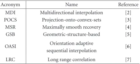
Table1: The names and the references for the benchmarked ap-proaches.
Acronym Name Reference
MDI Multidirectional interpolation [2] POCS Projection-onto-convex-sets [3] MSR Maximally smooth recovery [4] GSB Geometric-structure-based [5]
OASI Orientation adaptive
sequential interpolation [6]
LRC Long range correlation [7]
searches for an area in the image that best matches the pat-tern of this ring in a mean-squared error sense, and replaces the corrupted area with the pattern inside the best match-ing rmatch-ing. LRC is also exploited in the recent image inpaint-ing work by Bertalmio et al. [8], where the basic texture syn-thesis procedure for concealing the lost area is similar to the LRC concealment algorithm. By simultaneously filling in the structure and texture information of missing areas, the in-painting technique demonstrates excellent subjective quality when the missing area is relatively small compared with the size of the whole image. It is worth noticing that the image inpainting technique focuses more on the overall subjective quality and is not designed to optimize an objective error measure of the concealment quality (such as MSE or PSNR) on many small blocks.
2.2. Performance benchmarking
If an image is compressed by a block-based codec and trans-mitted over an error-prone channel, the error impairments are likely to be in the block domain. We focus on iso-lated block concealment in this work because block-based codecs are dominant for image or video transmission and the interleaving techniques can be employed in packetiza-tion to significantly reduce consecutive block loss [10]. Since various error concealment techniques employ quite diff er-ent “philosophies,” it was not conclusive from the litera-ture which one is the best. We attempt to address this issue through a benchmarking effort, which also sheds light on the design direction of a new concealment framework that can outperform the existing approaches.
Table2: Comparison of algorithms in concealment quality PSNR (dB). For each image, the scheme achieving the best performance is highlighted in bold font. The Better-2 column lists the concealment quality of the recovered images in which each concealed block is the better one selected between GSB and OASI.
Type Name Size MDI POCS MSR LRC GSB OASI Better-2
Bassharbor 512×512 29.47 28.12 28.83 27.84 30.69 30.37 31.46 Blueflower 512×512 27.88 27.55 27.09 26.77 29.68 29.85 31.04
House 512×512 28.78 26.08 27.00 26.86 29.47 30.00 30.98
Natural NewYork 512×512 24.25 21.00 23.66 22.80 24.13 24.52 25.29
Operahouse 512×512 30.91 28.88 28.53 29.08 30.88 31.30 32.38 Papermachine 512×512 29.77 28.46 25.80 31.78 33.85 33.75 36.12
Watch 512×512 31.40 29.59 29.41 31.35 33.77 33.99 35.52
Portrait
Lena 512×512 32.28 29.49 29.20 30.64 34.43 35.12 36.08
Barbara 512×512 27.41 23.35 27.14 29.78 29.26 30.79 31.80
Kid 480×480 31.86 29.62 29.57 30.21 33.47 33.45 34.98
Man 512×512 27.59 25.41 26.07 25.60 28.77 29.13 30.12
Circletrain 512×512 41.62 34.16 32.11 46.51 48.33 34.90 48.33
Artificial Tulip 512×512 29.74 28.05 26.71 27.61 33.22 33.47 35.13
Waterfall 512×512 27.92 26.36 26.52 26.18 28.79 29.12 30.20
Texture Bear 384×384 30.05 29.55 27.99 27.82 32.33 33.30 34.38
Figure1: A checkerboard pattern with 25% block loss used in the concealment experiments.
otherwise. We examine the quality of recovered images in terms of PSNR and the computation complexity in terms of the concealment speed, and summarize the results in Tables 2and3, respectively. All algorithms have been implemented in C/C++ with a moderate amount of optimization and the same speed-up settings, and tested on a 1.20 GHz Pentium-4 PC with 256 MB RAM.
We can see fromTable 2that among the three recent tech-niques reviewed earlier, the LRC approach does not outper-form the GSB and OASI approaches on most images. One reason is that the checkerboard error pattern leaves a very limited number of the candidate matching windows that do not suffer from the loss. The LRC approach does not per-form well on most natural scenery images either, since there are few repeating patterns. On the other hand, the GSB and
Table3: Comparison of algorithms in speed (seconds) for conceal-ing the “Lena” image usconceal-ing a 1.20 GHz Pentium-4 PC with 256 MB RAM.
MDI POCS MSR LRC GSB OASI
Lena 3.03 219.58 0.59 98.45 0.56 7.12
OASI approaches significantly outperform other approaches on these benchmark images, although neither of the two gives the best performance for all images. The lack of all-time champion suggests that the image characteristics vary signif-icantly from one to another, so a single algorithm based on an assumption about one aspect of the characteristics is not suitable for all images. This motivates us to go one step fur-ther and assemble a recovered image in which each concealed block is the better one selected between the GSB and OASI concealment results. As shown in the last column (“Better-2”) of Table 2, this assembled image gives a much higher overall concealment quality than using GSB or OASI alone.
Figure2: Illustration of better performing concealment scheme be-tween GSB and OASI on the “Lena” image: (white blocks) OASI performs better; (black blocks) GSB performs better; (gray blocks) GSB and OASI do not have significant performance difference.
2.3. Classification-based concealment
For a receiver to pick the better one between the two state-of-the-art techniques correctly is a nontrivial task. This is be-cause a receiver does not have the original undamaged im-age to compare with and determine which scheme gives bet-ter performance. Available to a concealment system are only the survived pixels that surround each corrupted block. If we could establish the connection between the image character-istics of the survived surrounding pixels and the correct se-lection between GSB and OASI using a training set, we could make a smart decision on which scheme to choose for a new damaged image.
To help exploring a rule in classifying the survived sur-rounding pixels, we take a close look at the “Better-2” test fromTable 2. For each block, we quantify the error conceal-ment performance of GSB and OASI by
P1= K
i=1
C1i−Oi,
P2=
K
i=1
C2i−Oi, (1)
whereK is the number of pixels in the block and is 64 in our case;Oiis the original value of theith pixel in the block; C1i and C2i are the corresponding recovered pixel values
by GSB and OASI, respectively. We visualize inFigure 2the scheme selection for each lost block of the “Lena” image. The gray blocks indicate that GSB and OASI do not have signifi-cant performance difference (i.e.,|P1−P2|<96); the white blocks indicate thatP2 is much smaller for the corresponding blocks; and the black blocks indicate thatP1 is much smaller. FromFigure 2, we do not observe any obvious trend in de-termining where GSB and OASI would perform better: the black blocks appear in both edges and some texture areas and so do the white blocks.
We further explore if one could deduce some simple rules from the spatial characteristics of survived pixels surround-ing the lost blocks. We define a smoothness feature from
(a) (b)
Figure3: Feature extraction from survived surrounding pixels: (a) grouping of survived pixels into small 2×2 segments, (b) scanning order for constructing a feature vector.
four layers of survived surrounding pixels as follows. First, we group the pixels into a total of 48 segments, and each seg-ment has 2×2 pixels, as shown inFigure 3(a). For each seg-ment, we generate a binary value characterizing smoothness: if the range of the pixel intensity in the segment exceeds a predetermined threshold of 15, we use “1” to indicate it as a nonflat segment; otherwise, we use “0.” Next, the binary val-ues from different segments are scanned according to the or-der inFigure 3(b)to form a feature vector, which is a binary sequence. We count the total number of 1s in the feature vec-tor (i.e., the number of nonflat segments) for each of the 15 images used in our benchmark test. For each possible count of nonflat segments, we also compute the ratio of the num-ber of blocks where OASI performs better versus those where GSB performs better. The relation is visualized inFigure 4, where we can see a general trend that GSB is likely to perform better on smooth blocks, and OASI tends to be better for tex-ture blocks. But the curve is not monotonic and the ratios do not deviate much from one, suggesting that we cannot re-liably determine the better performing concealment scheme just based on the nonflat segment count of the surviving sur-roundings.
0 0.5 1 1.5 2 2.5
Ou tpe rf o rming ratio: OSAI ve rs us GSB
5 10 15 20 25 30 35 40 45
The number of nonflat segments
Figure4: Examining the feasibility of a simple smoothness measure for distinguishing the better performing scheme: thex-axis repre-sents the number of nonflat segments in survived surroundings and they-axis represents the ratio of the block counts where OASI per-forms better to those where GSB is better.
be easily extended to incorporate other appropriate conceal-ment schemes and perceptual criteria.
3. RECEIVER-SIDE ADAPTIVE BLOCK CONCEALMENT USING SVM CLASSIFICATION
3.1. Classification based on support vector machine
We formulate a receiver’s choice of concealment scheme for each block as a supervised classification problem. Each error concealment method is considered as a class, and a feature vector is extracted from the pixels that surround an image block. In the training stage, we collect a number of feature vectors from training images, and label every feature vectorxi
with a ground truth class corresponding to the best conceal-ment method for the associated block. We train the classifier using these feature-class pairs.
We adopt support vector machine (SVM) classifiers, as they often exhibit good generalization performance [13,14] with theoretical insights of structural risk minimization [15, 16]. The design of an SVM classifier can be boiled down to a convex quadratic programming problem with global opti-mal solutions in training. For our two-class pattern classifi-cation problem that decides between the GSB and OASI con-cealment approaches, two kernel functions have been used to search for the optimal classification solution, namely, a linear kernel function and a radial kernel function.
3.1.1. Linear SVM
The linear SVM determines a linear discriminant function (a hyperplane) that gives the maximum separation margin be-tween the two classes of training data [15]. The optimization
problem can be formulated as
minimizef(w,b)= w2, subject toyi
xT
iw+b
−1≥0, (2)
wherexiis theith training feature vector andyi ∈ {−1, 1}
represents the corresponding class label. The separating hy-perplane is parameterized by a vector w and a scalar b, wherewis the norm of the separating hyperplane. The La-grangian multiplier formulation for this constrained opti-mization problem is
Lp=
1 2w
2− l
i=1
αiyi
xTiw+b
+
l
i=1
αi, (3)
where{αi}is a set of Lagrangian multipliers. Now, the
prob-lem is reduced to minimizing Lp with respect to w andb
under the following restrictions: (i) the derivatives of Lp
with respect to allαi’s vanish and (ii)αi ≥0. For this
con-vex quadratic programming problem, it is well established that the solution can be obtained through the Karush-Kuhn-Tucker (KKT) conditions or through an easierdualproblem [15].
When the training data of the two classes is linearly sep-arable, the linear kernel SVM approach gives a classifier in the form of a hyperplane separating the two classes of train-ing data with the largest margin. If the traintrain-ing data is not linearly separable, a positive slack variableξi(ξi≥0) can be
introduced to alleviate the sensitivity of noisy training pat-terns [17]:
yi
xTiw+b
−1 +ξi≥0, (4)
Lp=1
2w
2+C l
i=1
ξi− l
i=1
αi
yi
xTiw+b
−1+ξi
− l
i=1
uiξi,
(5)
whereCis a parameter adjusting the relative penalty given to the classification errors on the training data.
To use a trained classifier to classify a new test samplez, we evaluate the sign of the following function:
f(z)=wTz+b=
Ns
i=1
αiyixiTz+b. (6)
Here,wis explicitly determined by a set ofNs support vec-tors, which are such training vectors that lie closest to the hy-perplane separating the two classes [15]. The sign reflects on which side of the decision boundary thatzlies and thus de-termines the classification result.
3.1.2. Handling nonlinearity
y-axis
x-axis
Unable to use linear kernel to find a
hyperplane
(a)
y-axis
x-axis
User linear kernel to find a set of hyperplanes
by subgrouping
(b)
Figure5: Handling the nonlinearity by a divide-and-conquer technique that trains a set of classifiers, one for each subset of the feature space.
and in general are far from separable by a linear discrimina-tion funcdiscrimina-tion in the original vector space. The nonseparabil-ity by a linear discrimination function can be handled in two ways. One is to extend the linear SVM with the kernel tech-nique and the other is to divide the vector space into groups and find one classifier for each group.
Nonlinear classification functions [15] can be built by replacing the dot product termxi,xj = xTixj in the
lin-ear kernel SVM by an appropriate kernel functionK(xi,xj).
This is equivalent to transforming feature vectors to a higher-dimensional spaceHthrough a mappingΦ :Rd →H, and
then finding a linear SVM classifier in this new space with K(xi,xj)= Φ(xi),Φ(xj). The radial basis kernel function
in the form of
Kxi,xj
=e−xi−xj2/2σ2 (7)
is commonly used for its good generalization capabilities, es-pecially when very limited information is available about the data distribution and separability for all classes. Here,σ is the width of the radial basis. It affects the classification per-formance substantially and will be addressed later in this sec-tion.
An alternative way of dealing with the nonlinearity is to use a divide-and-conquer technique. The idea is illus-trated by the two-dimensional example shown inFigure 5, where the two classes of data represented inFigure 5(a)are not linearly separable. However, if we divide the space into four stripes as shown by the dashed lines inFigure 5(b), the data within each stripe becomes more separable by a lin-ear function. The subdivision of the feature space naturally accommodates the nonlinearity in the class boundary, yet the training process is comprised of training a set of rel-atively simple linear SVMs. Subdividing the feature space into nonoverlapped subsets can be done through dividing
the dynamic range of some feature elements or according to the norm of the feature vector. The latter reflects the over-all smoothness of the surrounding pattern for the feature vector defined in Section 2, as the L1 norm of the vector gives the total number of nonflat 2×2 segments over the 48 pixel segments surrounding a lost block. Recalling the trend seen in Figure 4on the classes as a function of the overall smoothness, the subdivision allows us to naturally adapt to the changing characteristics.
The nonlinearity in the classification can also be handled using a combination of the above two approaches. This hy-brid approach divides the feature space into subsets and pro-vides a nonlinear SVM (such as the radial kernel function) for each subset. It offers a great amount of flexibility, allow-ing the subsets to use different kernel parameters (such asσ in the radial basis function) or even different kernels. The nonlinear SVM obtained for each subset of feature space can have a much smaller number of support vectors; hence can be considerably simpler than a nonlinear SVM trained for the entire space. As such, the hybrid approach has a low com-putational complexity in both the training and test phases.
3.1.3. Determining kernel parameters
Training process
Training images
Preprocessing (determine kernel parameters)
Selecting training samples
Constructing feature vectors
Subgrouping
Training set of feature vectors SVM training
Trained SVM classifiers
Concealment process
Images
Constructing feature vectors
Subgrouping
Feature vectors
Concealment method Calculating the concealment
method selection based on the trained SVM models
Error concealment
Recovered images
Figure6: Block diagram of the proposed receiver-side classifica-tion-based concealment approach.
Step 1. Dividing the training samples into two subsets,Aand
B: in each iteration below, we use setAfor training and set
Bfor validation.
Step 2. Choosing kernel parameters and constructing a new
training setR: we adjust kernel parametersσ(1)andC(1)so
that the sum of training errors onAand validation errors on
Bis minimized. More generally, we may employ an objective function using a weighted sum of the two types of errors, and low error rate on the validation set is often desirable to en-sure a good generalization capability of the classifier. Since SVM is known to generalize well and does not usually suffer from overfitting problem as much as the conventional classi-fiers do, we choose to minimize the sum of errors (i.e., with equal weights) for simplicity. A new training set Ris then generated consisting of the support vectors from setAand the successfully classified samples from setB.
Step 3. Switching subsets: we switch setAwith setBand
re-peatStep 2. We record the kernel parameters asσ(2)andC(2) and denote the new training set asS. The union of setRand setSbecomes the final training setT.
Step 4. Determining kernel parameters: the kernel
parame-ters obtained from the two iterations above provide a search
range for determining the final parameters. For example,σ(1) andσ(2)specify a range over which we will search for the fi-nal value ofσthat can minimize the training error on setT. Other kernel parameters can be jointly determined through the search.
In addition to determining kernel parameters, we also fil-ter out the samples that have very similar values but different class labels. These samples are usually located in such region of the feature space that is difficult to classify and they can make the classification boundary very complex. Removing them from the training set helps improve the generalization capability of the classifier.
3.2. Overall algorithm
The overall algorithm of our proposed receiver-side classifi-cation-based block concealment is summarized inFigure 6. Below we explain a few additional details of the training and concealment processes.
3.2.1. Selection of training data
We choose a set of training images that represent a variety of characteristics. Because of the spatial correlation in most natural images, we use about one fourth of blocks in the checkerboard pattern from each training image as candidates to form a training set. As discussed earlier, we further filter out the blocks where different concealment schemes do not give substantially different performance.
3.2.2. Construction of feature vectors
Since different spatial block concealment techniques may use different sets of surrounding pixels, the feature vectors de-rived for classification should come from the union of the sets of pixels used by these techniques. For example, GSB often uses two surrounding layers to extract the geomet-ric structure information, while OASI uses four surrounding layers to compute the interpolation coefficients. The classi-fication region should therefore includes four surrounding layers of pixels. For block size of 8×8, 192 pixels are involved in classification.
While pixels can be used directly as features, they often require a sophisticated kernel function to ensure separabil-ity and thus incur high computation complexseparabil-ity. We gener-ate a more compact feature vector from pixel values using a similar approach as described inSection 2.3and summarized as follows. We first partition the four surrounding layers of pixels into segments, as illustrated inFigure 3(a). For theith segment of four pixels, the feature valuevicharacterizes the
smoothness of the segment and is computed as
vi=floor
max pk
−min pk
−s/Qv
+ 1, (8)
where{pk}are the pixels in theith segment, the floor
func-tion returns the largest integer less than or equal to the in-put. The two parameterssandQvcontrol the sensitivity of
the feature. We chooses = 15 andQv = 50 based on our
Table4: Overall classification accuracy on the 13 test images.
1 group 16 subgrouping 48 subgrouping 48 subgrouping with
preprocessing
Linear SVM 50.55% 65.96% 66.26% 67.11%
Radial SVM 65.54% 66.75% 67.17% 70.16%
a vector. The ordering of features in the feature vector does not affect the performance of a trained SVM classifier since the kernel functions widely used in SVM classification are in-variant with respect to the ordering of features.
3.2.3. Subgrouping
As discussed earlier, to handle the nonlinearity of the class boundary, we divide the feature space intonsubsets and train an SVM classifier for each subset. We use a simple empirical partitioning rule based on the number of nonzero values in a feature vector.
3.2.4. Preprocessing of training samples
The feature vectors we used for training are divided into sets
AandB. Each set includes images from all four representa-tive categories mentioned before, namely, portraits, artificial images, natural scenery images, and rich texture images. We determine in this step the kernel parameters and training set using the approaches described inSection 3.1.3.
3.2.5. Concealment process
After the training process is performed off-line, the parame-ters of trained SVM classifiers are stored in the receiver sys-tem. To conceal a corrupted image block, the receiver system use the same approach as in the training process to construct feature vector and identify to which subgroup the feature vector belongs. The classification result will then determine which concealment scheme to use.
3.3. Experimental results and performance analysis
In this section, we present the experimental results on the proposed block concealment method using receiver-side classification. We use the SVMlighttoolkit [18] to accomplish this classification task. SVMlightis an implementation of SVM based on the optimization algorithm in [19].
A total of 15 images are used for training and 13 for test-ing, which are shown inFigure 11. There are a total of 5 562 blocks in the training images and 3 804 blocks in the test im-ages having substantially different concealment performance by GSB and OASI. These blocks are used to evaluate the clas-sification accuracy.
We first train a linear SVM using the 48-dimension fea-ture vectors of all training blocks. The classification accu-racy of this trained linear SVM on the test blocks is only 50.55%. The failure of this classification experiment indi-cates the high nonlinearity in the boundary of the two classes.
We then examine the effects of various approaches in han-dling the nonlinearity. The simulation results of this explo-ration are shown in the first row of Table 4. We compare the cases of no subgrouping, 16-group subgrouping, and 48-group sub48-grouping. For these three cases, the kernel param-eters are chosen that can provide the highest classification accuracy on three of the training images, “Lena,” “Barbara,” and “Bassharbor.” We also consider the case of applying pre-processing with 48-group subgrouping for thorough selec-tion of kernel parameters and filter out noisy samples, us-ing the approaches described inSection 3.1.3. As shown in the table, subgrouping significantly improves the classifica-tion accuracy by more than 15%; and preprocessing and finer subgrouping can further improve the classification accuracy. Based on results from the above exploration, we adopt 48 subgroups with preprocessing procedure for our train-ing process and examine the concealment performance of the proposed receiver-side classification-based scheme on the thirteen 8-bit gray-scaled test images. The classification accu-racy for each subgroup ranges from 58.82% to 83.09%, and the overall classification accuracy is 67.11%. From the com-parison of concealment results with that of GSB [5] and OASI [6] inTable 5, we can see that the classification-based method with a linear kernel has up to 0.84 dB gain when compared to the GSB method and up to 1.06 dB gain when compared to the OASI method.
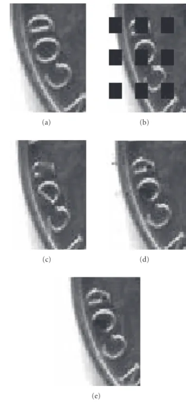
We then train a radial basis kernel SVM to evaluate how well it handles the nonlinearity of training data. The prepro-cessing and subgrouping are also evaluated for this nonlin-ear kernel. As with the linnonlin-ear kernel, the radial basis kernel can also benefit from the preprocessing and finer subgroup-ing for improvsubgroup-ing the classification accuracy, although the improvement due to grouping is less significant on the ra-dial basis kernel than on the linear kernel. This latter aspect is expected as the radial basis kernel has a good capability of handling the nonlinear classification boundary even with-out subgrouping. The classification accuracy for each group ranges from 60.00% to 80.53%, and the overall classification accuracy is 70.16%. As shown inTable 5, the classification-based method using the radial basis kernel SVM has up to 0.94 dB gain compared to the GSB method and up to 1.26 dB gain when compared to the OASI method. The proposed scheme consistently outperforms the two prior algorithms on all test images. As an example, we show a portion of the “Nickel” image inFigure 7, and we can see that the proposed concealment scheme provides better visual quality and leaves fewer artifacts.
Table5: Comparison of concealment quality in PSNR (dB) of existing concealment schemes and the proposed receiver-side classification-based approaches.
Type Name Size GSB OASI Better-2 Linear kernel Radial kernel
Fishingboat 512×512 30.93 31.10 32.28 31.36 31.64
Goldhill 512×512 32.35 32.41 33.52 32.63 32.84
Peppers 512×512 35.18 35.55 36.72 36.02 35.79
Skylinearch 400×400 32.01 31.34 33.22 32.40 32.60
Natural Lochness 512×512 32.74 32.33 33.40 32.78 32.78
Bellflower 512×512 33.27 33.70 35.57 34.12 34.21
Brandyrose 512×512 39.47 39.27 40.42 39.86 39.80
Lake 512×512 28.54 28.73 30.14 29.10 29.04
F14 496×496 38.64 38.86 39.88 38.75 39.05
Portrait Elaine 512×512 35.17 35.93 36.35 35.85 35.96
Couple 512×512 30.74 31.06 32.22 31.49 31.43
Artificial Nickel 256×256 29.05 28.55 30.53 29.33 29.58
Texture Baboon 512×512 26.11 26.48 27.12 26.62 26.62
The small improvement in classification accuracy, however, does not always translate into the improvement of conceal-ment quality. For example, we can see from Table 5 that radial basis kernel provides slightly better concealment for some test images, while linear kernel is better for others. This is because the set of accurately classified blocks may be different by the two kernel techniques, and the quality gain on the slightly bigger set of accurately classified blocks may not always offset the quality loss on the falsely classified ones. On the other hand, we see that the classification-based schemes give consistently higher concealment quality than the two current state-of-the-art algorithms. With more ac-curate classification, the concealment quality can be further improved. Along the line of seeking more accurate classifi-cation information, we are inspired by the growing impor-tance of involving both sender and receiver in efficient and reliable multimedia communications. In the next section, we investigate what role the sender system can play in facilitating classification-based concealment.
4. BLOCK CONCEALMENT WITH SENDER-SUPPLIED CLASSIFICATION INFORMATION
The receiver-side classification algorithm proposed in Section 3 outperforms the conventional error concealment approaches. Coming with such benefit is the increase in com-putation complexity at receiver-side for performing classifi-cation. The increased complexity may pose a challenge for systems that have very limited computation resources and/or stringent real-time rendering constraints. If some parts of the concealment task could be moved to the sender side, it would help reduce the computation burden on the receiver side, as demonstrated in several recent works [9,10].
An important benefit of moving the classification task from a receiver to a sender is that it allows for an easy access of the perfect classification information. This is because the sender has full reference to the original, uncorrupted image,
and can compare the concealment quality by various tech-niques to obtain the ground truth about which technique works better. The higher accuracy of the classification infor-mation can further improve the overall concealment qual-ity upon what we have achieved in Section 3, which is an even more attractive advantage than the reduced receiver-side computation complexity.
In this section, we extend the classification-based con-cealment framework from a sender-driven perspective to de-sign and evaluate error concealment schemes with sender-supplied classification information. We will examine two main approaches to conveying the classification information from a sender to a receiver: one is to attach the side informa-tion in the header and the other is to embed the side infor-mation in the image signal using data hiding technique.
4.1. Conveying classification information by attachment
A quite straightforward way to convey the classification in-formation from the sender to the receiver is to transmit the information along with the image, for example, in the image header. The side information requires extra bandwidth, and therefore, the appropriateness of the attachment approach depends on the application and the image/video size. An al-ternative approach to avoid the increase in bandwidth is to encode the image at a lower rate to spare room for side in-formation. This would reduce the image quality, leading to a similar tradeoffas in the data embedding approach to be discussed in the next subsection.
We present the system block diagram of the sender-side attachment scheme inFigure 8. On the sender side, in ad-dition to encoding an image as usual, the system would perform the following tasks:
(a) (b)
(c) (d)
(e)
Figure7: Visual quality comparison of three concealment schemes: (a) original image; (b) corrupted image; (c) recovered image using GSB; (d) recovered image using OASI; and (e) recovered image us-ing the proposed classification-based method.
(2) compare the quality of the images obtained by these concealment methods and classify each block accord-ing to the winnaccord-ing technique;
(3) encode the classification information for each block, possibly using lossless compression techniques; (4) attach the classification information to the compressed
image bit stream.
On the receiver side, upon detecting the corrupted blocks, the receiver will extract the classification information from the received stream and use this side information to select the appropriate method for concealing each corrupted block. We can further apply forward error correction coding with ap-propriate strengths to protect the image stream and the side information.
Regarding the detailed encoding method for side infor-mation, we denote the side information for the GSB con-cealment method as “0” and that for OASI as “1.” The side information for all blocks can be put together as a binary se-quence. Recall that GSB concealment has lower computation complexity than OASI. So as before, we choose the error con-cealment technique with lower computation complexity for the blocks where the performance of the two concealment methods are not significantly different. This also helps give a long run of “0” in the side-information encoding. We then apply run-length coding and arithmetic coding to compress the binary sequence of classification information.
It can be seen that the attachment scheme trades ad-ditional bandwidth for improved concealment quality. The tradeoffcan be adjusted as follows. For each block, the per-formance of each algorithm (P1 andP2) is calculated accord-ing to (1). The binary-valued side informationLfor the block is determined by
L=
⎧ ⎨ ⎩
1, ifP1−P2>Δth,
0, otherwise, (9)
whereΔthis a threshold. An experiment with different set-tings ofΔth is performed on the JPEG-compressed “Lena” image with quality factorQ=80%, where the image size is 512×512 and the JPEG file size is 303 072 bits. As shown in Figure 9, the largerΔthwe choose, the lower PSNR we get. On the other hand, since more blocks are labeled as “0” with a largerΔth, compressing the classification information us-ing run-length codus-ing and arithmetic codus-ing will achieve a higher compression ratio. The results inFigure 9shows that whenΔthis around 96, the gain in error concealment quality is significant, yet the additional bandwidth for classification side information is quite moderate and only about one per-cent of the image file size. Thus we use this value to evaluate the overall concealment quality.
The simulation results of the attachment scheme are listed in Table 6. The results suggest that our proposed concealment scheme by attaching classification information outperforms each individual receiver-side concealment ap-proach. The error concealment quality can be improved by about 1 ∼ 2 dB when compared to the better one between the two individual methods. Readers may notice that the at-tachment scheme has 0 dB gain on the “Circletrain” image when compared to GSB. As shown inFigure 11, this artificial image has uniform background and smooth edges. GSB gives better concealment quality in terms of PSNR for every recov-ered blocks, so we cannot get any improvement compared to GSB.
4.2. Conveying classification information by embedding
Sender
Attaching side information to image stream Original
images Source
coding
Channel coding
Transmitting Error
concealment
by method 1 Performance comparison
Side information
Source coding
Channel coding Error
concealment by method 2
Receiver Receiving
Image stream channel decoding
Source decoding
Error concealment
Recovered images
Error concealment method selection Side information
channel decoding
Source decoding
Figure8: Block diagram of the sender-side attachment approach.
50 100 150 200 250 300 350 400 450 500 550 The threshold for the performance difference
34.8 35 35.2 35.4 35.6
PSNR
(dB)
(a)
50 100 150 200 250 300 350 400 450 500 550 The threshold for the performance difference
10 15 20 25 30×10
2
Band
w
idth
u
sage
for
the
side
infor
mation
(bit)
(b)
Figure9: Relation of the thresholdΔthversus the concealment quality and the bandwidth required for side information, respectively, when
applying the sender-side attachment approach on the “Lena” image.
of the image plus the side information is unchanged. A viable alternative to convey side information with little additional bandwidth is embedding it in the image. More specifically, we embed 1-bit classification information of a block into its neighboring block. The embedding will be incorporated
Table6: Performance evaluation of the sender-side attachment approach.
Image type Image name JPEG file Side-information Quality gain Quality gain size (bytes) size (bytes) over GSB (dB) over OASI (dB)
Bassharbor 50 867 368 0.52 1.14
Blueflower 53 528 495 0.87 0.90
House 46 975 361 1.28 1.26
Natural Newyork 73 830 436 0.89 0.67
Operahouse 48 666 365 1.09 0.99
Papermachine 41 773 285 1.95 2.07
Watch 41 773 293 1.23 1.09
Portrait
Lena 37 884 287 0.99 0.93
Barbara 50 867 424 2.21 1.12
Kid 30 791 257 1.12 1.08
Man 61 810 431 0.80 0.79
Circletrain 15 709 124 0 11.19
Artificial Tulip 48 641 437 1.45 1.68
Waterfall 44 734 292 0.93 0.75
Texture Bear 26 089 280 1.32 1.12
Original images
Sender
DCT Quantization Data embedding Source coding
Channel coding
Transmitting Error
concealment by method 1
Side information Performance
comparison Error
concealment by method 2
Receiver Receiving
Channel decoding
Source decoding
De-quantization IDCT
Error concealment
Recovered images
Error concealment method selection Extract side
information
Figure10: Block diagram of the sender-side embedding approach.
simultaneously. As we will see later in this subsection, the embedding in the neighboring block has additional advan-tage when dealing with smooth blocks. We summarize the system block diagram inFigure 10and explain a few details of embedding below.
As can be seen from the previous subsection, the amount of classification information is on the order of a couple of thousand bits, which calls upon an embedding technique with quite high embedding rate. Unlike many copyright
protection applications, there is no major adversary to cir-cumvent the embedded data in error concealment applica-tion, where the side information helps improve the perfor-mance of image communications [20]. The quantization-based data embedding is a viable choice to meet these re-quirements [21].
Bassharbor (512×512) Blueflower (512×512) House (512×512) Newyork (512×512) Operahouse (512×512)
Papermachine (512×512) Watch (512×512) Lena (512×512) Barbara (512×512) Kid (480×480)
Man (512×512) Circletrain (512×512) Tulip (512×512) Waterfall (512×512) Bear (384×384)
Fishingboat (512×512) Goldhill (512×512) Peppers (512×512) Skylinearch (400×400) Lochness (512×512)
Bellflower (512×512) Brandyrose (512×512) Lake (512×512) F 14 (496×496) Elaine (512×512)
Couple (512×512) Nickel (256×256) Baboon (512×512)
Table7: Performance evaluation of the sender-side embedding approach. Images are in JPEG format with quality factorQ=80%.
Image type Image name PSNR of image Concealment gain Concealment gain
after embedding (dB) over GSB (dB) over OASI (dB)
Bassharbor 41.89 0.14 0.76
Blueflower 41.73 0.77 0.80
House 42.01 1.00 0.98
Natural Newyork 38.25 0.74 0.52
Operahouse 40.57 0.63 0.53
Papermachine 42.42 1.02 1.14
Watch 42.82 0.74 0.60
Portrait
Lena 43.21 0.30 0.24
Barbara 42.25 1.94 0.85
Kid 43.16 0.60 0.56
Man 39.48 0.49 0.48
Circletrain 47.36 −2.80 8.39
Artificial Tulip 42.31 0.78 1.01
Waterfall 40.47 0.62 0.44
Texture Bear 43.91 0.63 0.43
substantial impact on compression size and visual quality of the image, the classification information for each block is embedded into the last quantized nonzero DCT coefficient in a zigzag scan order. The coefficient is forced to be an even value if we want to embed “0,” or an odd value if to embed “1,” and the embedding tries to make minimum necessary changes to enforce such a relation. If all the quantized AC coefficients in a block are zero, which we would encounter for smooth blocks, we will not make any changes on the co-efficients. In this case, the receiver would consider a “0” to be embedded in the block based on the above-mentioned rules, and apply the concealment technique of lower compu-tation complexity (i.e., GSB) for the corrupted block. Such an arrangement works well in practice. This is because GSB usually performs better for blocks with relatively “flat” sur-rounding; in the mean time, the characteristics of nearby blocks are likely to be similar and can be fully exploited by neighborhood embedding presented earlier, where classifica-tion informaclassifica-tion is embedded into neighboring block.
The experimental results of the embedding scheme are shown in Table 7. The improvement of concealment qual-ity on most images is significant: we have a 0.14 ∼1.94 dB gain compared to GSB and 0.24∼1.14 dB gain compared to OASI. For most images, GSB performs better on some blocks and OASI performs better on some other blocks. As such, the quality degradation introduced by the embedding procedure is overcome by the substantial concealment gain compared to either GSB or OASI alone. An interesting exception ap-pears on the “Circletrain” image. Different from other im-ages, GSB is the better selection for all blocks in the “Cir-cletrain” image and the concealed quality is very high (with the PSNR dB value being in high forty). The sender-supplied classification information thus provides no gain when com-pared to using GSB alone. On the other hand, the embed-ding technique inevitably introduces a moderate amount of
quality degradation. As a result, for the “Circletrain” image, the embedding scheme achieves a net loss of 2.8 dB in PSNR compared to GSB, although little visual difference could be visible at such high PSNR levels. In comparison with OASI, the gain over OASI is over 8 dB and is much more noticeable.
5. COMPARISONS AND DISCUSSIONS
In the previous two sections, we have proposed three classification-based error concealment schemes to improve the concealment quality. Among the three schemes, one per-forms classification on the receiver side using an SVM classi-fier and features derived from the survived pixels surround-ing a corrupted block, and the other two schemes convey the sender-supplied classification information to receiver by at-tachment and embedding, respectively. As we can see from Tables5,6, and7, they all improve the concealment qual-ity quite substantially. In this section, we compare the three schemes, discuss their advantages and shortcomings, and identify the application scenarios that each scheme is suitable for. We also discuss a few directions for further extension and generalization.
Table8: Comparison of concealment quality in PSNR (dB) by the receiver-side and sender-side approaches. Images are in JPEG format with quality factorQ=80%.
Image type Image name GSB OASI Receiver-side Sender-side Sender-side
classification embedding attachment
Natural Fishingboat 30.81 30.87 31.03 31.55 32.02
Portrait Elaine 35.47 35.18 35.43 35.84 36.22
Artificial Nickel 28.48 28.41 28.71 29.40 29.93
Texture Baboon 26.02 26.19 26.25 26.45 26.74
for sending side information without additional bandwidth. The receiver-side classification scheme has the smallest im-provement over individual scheme because the classification result at the receiver is not always accurate.
In addition to the visual quality of concealed image, other important issues include computational complexity, band-width usage, and complexity associated with overall system deployment. The receiver-side classification-based error con-cealment requires neither side information to be sent nor any special involvement of a sender. It can be therefore in-tegrated in a standard-compliant coding system. The train-ing involves a large amount of computation but can be per-formed off-line. A moderate amount of run-time computa-tion power is required from the receiver to extract features and feed them into a trained SVM classifier to determine which concealment scheme to use, and this is done only for corrupted blocks. As the classification results are not always perfect and depend heavily on the generalization capability of the classifier, the concealment performance may vary sub-stantially from one image to another. This scheme is suitable for applications where there is limited design flexibility on the sender side.
The schemes with sender-supplied classification infor-mation provide more proactive protection. They require a significant amount of computation power and cooperation on the sender side to perform concealment, provide ground truth on the concealment scheme to use foreveryblock, and encode or embed the classification information with the im-age. The attachment scheme requires additional bandwidth to deliver the ground truth of classification. After such an at-tachment, the resulting media stream may not be standard-compliant. In contrast, the embedding scheme can maintain standard compliance of the resulting media stream. This is at an expense of minor reduction of the perceptual qual-ity in the transmitted image, even when the transmission is free from error. On the other hand, the more accurate sender-supplied classification information provides substan-tial improvement in concealment quality and also eliminates the computation needed on the receiver side for classifica-tion. These schemes are suitable for applications with pow-erful sender and simple receiver and for scenarios where the visual data is encoded once but delivered and consumed by many users.
The spatial concealment schemes investigated in this pa-per can be used for both image and video transmissions. They can be applied to each corrupted video frame and can be used in conjunction with other temporal concealment
methods [23, 24]. The schemes that maintain standard-compliance of the transmitted video, such as the receiver-end classification and the embedding schemes, allow image/video to be handled by a number of existing visual communica-tion systems that support the standard, with few addicommunica-tional changes to the system.
In addition to conveying side information to facilitate concealment, data embedding can also be used for detecting corrupted blocks [25]. For this error detection purpose on each block, the parity information or some known patterns should be embeddedinsidethe corresponding block. The re-ceiver will check the correctness of the parity or the integrity of the patterns to determine whether the block is corrupted. On the other hand, the side information of a block for facil-itating its concealment must be storedoutsidethat block, as seen in the algorithm presented inSection 4.
We have so far assumed that the block damage is isolated (i.e., all neighboring blocks of the damaged one are correctly received). Since consecutive block damage is a challenge to most error concealment techniques, interleaving techniques have been suggested in packetization to avoid packing neigh-boring blocks together [1, 10]. As such, consecutive block losses rarely happen at a moderate loss rate. In case when there remain some consecutive block losses, both GSB and OASI techniques have been demonstrated to handle a small number of consecutive blocks [5,6]. The classification can also be extended to cope with this case, for example, to in-corporate the loss of two horizontal or vertical neighboring blocks by training additional classifiers. And since what we have proposed is a general framework, it can be further ex-tended to incorporate other concealment techniques and ac-commodate more than two candidate techniques.
6. CONCLUSIONS
the error concealment performance. The advantages of each of the three proposed schemes have been analyzed and the suitable application scenarios suggested. Our experiments on a diverse set of images have shown that the proposed classification-based concealment framework provides up to 2 dB higher concealment quality over the current state-of-the-art algorithms.
ACKNOWLEDGMENTS
This research was supported in part by research grants from US National Science Foundation CCR-0133704 (CAREER). Preliminary results of this paper were presented in the IEEE International Conference on Image Processing (ICIP’03) [26]. The authors would like to thank Professor Wenjun Zeng of the University of Missouri, Columbia, for providing the source code of the GSB error concealment algorithm.
REFERENCES
[1] Y. Wang and Q.-F. Zhu, “Error control and concealment for video communication: a review,”Proceedings of the IEEE, vol. 86, no. 5, pp. 974–997, 1998.
[2] W. Kwok and H. Sun, “Multi-directional interpolation for spa-tial error concealment,”IEEE Transactions on Consumer Elec-tronics, vol. 39, no. 3, pp. 455–460, 1993.
[3] H. Sun and W. Kwok, “Concealment of damaged block trans-form coded images using projections onto convex sets,”IEEE Transactions on Image Processing, vol. 4, no. 4, pp. 470–477, 1995.
[4] Y. Wang, Q.-F. Zhu, and L. Shaw, “Maximally smooth image recovery in transform coding,”IEEE Transactions on Commu-nications, vol. 41, no. 10, pp. 1544–1551, 1993.
[5] W. Zeng and B. Liu, “Geometric-structure-based error con-cealment with novel applications in block-based low-bit-rate coding,”IEEE Transactions on Circuits and Systems for Video Technology, vol. 9, no. 4, pp. 648–665, 1999.
[6] X. Li and M. T. Orchard, “Novel sequential error-concealment techniques using orientation adaptive interpolation,” IEEE Transactions on Circuits and Systems for Video Technology, vol. 12, no. 10, pp. 857–864, 2002.
[7] D. Zhang and Z. Wang, “Image information restoration based on long-range correlation,”IEEE Transactions on Circuits and Systems for Video Technology, vol. 12, no. 5, pp. 331–341, 2002. [8] M. Bertalmio, L. Vese, G. Sapiro, and S. Osher, “Simultaneous structure and texture image inpainting,”IEEE Transactions on Image Processing, vol. 12, no. 8, pp. 882–889, 2003.
[9] P. Yin, B. Liu, and H. H. Yu, “Error concealment using data hiding,” in Proceedings of IEEE International Conference on Acoustics, Speech, and Signal Processing (ICASSP ’01), vol. 3, pp. 1453–1456, Salt Lake City, Utah, USA, May 2001. [10] P. Yin, M. Wu, and B. Liu, “Robust error-resilient approach for
MPEG video transmission over Internet,” inVisual Communi-cations and Image Processing (VCIP ’02), vol. 4671 of Proceed-ings of SPIE, pp. 103–111, San Jose, Calif, USA, January 2002. [11] Y. Liu and Y. Li, “Error concealment of digital images using
data hiding,” inProceeding of 9th IEEE DSP Workshop, Hunt, Tex, USA, October 2000.
[12] K.-H. Jung, J.-H. Chang, and C. W. Lee, “Error concealment technique using projection data for block-based image cod-ing,” inVisual Communications and Image Processing (VCIP ’94), vol. 2308, part 3 ofProceedings of SPIE, pp. 1466–1476, Chicago, Ill, USA, September 1994.
[13] R. O. Duda, P. E. Hart, and D. G. Stork,Pattern Classification, John Wiley & Sons, New York, NY, USA, 2nd edition, 2001. [14] T. Joachims, “Text categorization with support vector
ma-chines: learning with many relevant features,” inProceedings of 10th European Conference on Machine Learning (ECML ’98), pp. 137–142, Chemnitz, Germany, April 1998.
[15] C. J. C. Burges, “A tutorial on support vector machines for pattern recognition,”Data Mining and Knowledge Discovery, vol. 2, no. 2, pp. 121–167, 1998.
[16] V. N. Vapnik, The Nature of Statistical Learning Theory, Springer, Berlin, Germany, 1995.
[17] A. J. Smola, P. Bartlett, B. Sch¨olkopf, and D. Schuurmans, Advances in Large Margin Classifiers, MIT Press, Cambridge, Mass, USA, 1999.
[18] T. Joachims, “SVMlightSupport Vector Machine V5.00,” 2002, http://svmlight.joachims.org.
[19] T. Joachims, “Making large-scale SVM learning practical,” inAdvances in Kernel Methods—Support Vector Learning, B. Sch¨olkopf, C. J. C. Burges, and A. J. Smola, Eds., pp. 169–184, MIT Press, Cambridge, Mass, USA, 1999.
[20] M. Wu and B. Liu,Multimedia Data Hiding, Springer, New York, NY, USA, 2002.
[21] M. Wu and B. Liu, “Data hiding in image and video: Part-I Fundamental issues and solutions,”IEEE Transactions on Im-age Processing, vol. 12, no. 6, pp. 685–695, 2003.
[22] M. Wu, H. H. Yu, and A. Gelman, “Multi-level data hiding for digital image and video,” inMultimedia Systems and Applica-tions II, vol. 3845 ofProceedings of SPIE, pp. 10–21, Boston, Mass, USA, September 1999.
[23] C. Dovrolis, D. Tull, and P. Ramanathan, “Hybrid spa-tial/temporal loss concealment for packet video,” in Proceed-ings of the 9th International Packet Video Workshop (PVW ’99), New York, NY, USA, April 1999.
[24] Y.-C. Lee, Y. Altunbasak, and R. M. Mersereau, “A temporal error concealment method for MPEG coded video using a multi-frame boundary matching algorithm,” inProceedings of IEEE International Conference on Image Processing (ICIP ’01), vol. 1, pp. 990–993, Thessaloniki, Greece, October 2001. [25] M. Chen, Y. He, and R. L. Lagendijk, “A fragile watermark
error detection scheme for wireless video communications,” IEEE Transactions on Multimedia, vol. 7, no. 2, pp. 201–211, 2005.
[26] M. Chen, M. Wu, and Y. Zheng, “Classification-based spatial error concealment for images,” inProceedings of IEEE Inter-national Conference on Image Processing (ICIP ’03), vol. 2, pp. 675–678, Barcelona, Spain, September 2003.
Meng Chenreceived the B.E. and M.E. de-grees from Xi’an Jiaotong University, China, in 1994 and 1997, respectively, and the M.S. degree from University of Maryland, Col-lege Park in 1999, all in electrical engineer-ing. Currently she is a Senior Design Engi-neer at Spirent Communications, and pur-suing her Ph.D. degree in signal processing and communications at University of Mary-land, College Park. Previously she worked at
Yefeng Zhengreceived the B.E. and M.E. degrees from the Department of Electronic Engineering, Tsinghua University, Beijing, China, in 1998 and 2001, respectively. Cur-rently, he is pursuing the Ph.D. degree in the Department of Electrical and Computer Engineering at the University of Maryland, College Park. His research interests include document image analysis, pattern recogni-tion, and computer vision. As a codeveloper
of an Asian OCR system during his Master’s program, he won the National Scientific and Technological Progress Award (2nd class) of China in 2003.
Min Wureceived the B.E. degree in elec-trical engineering and the B.A. degree in economics (both with the highest honors) from Tsinghua University, Beijing, China, in 1996, and the Ph.D. degree in electri-cal engineering from Princeton University in 2001. Since 2001, she has been an Assis-tant Professor of the Department of Electri-cal and Computer Engineering and the In-stitute of Advanced Computer Studies at the