...
REPAIR AGREEMENT
The Mainframe sold hereunder is sold "as is", with all faults and without any warranty, either expressed or implied, including any implied warranty of fitness for intended use or merchantability. However, the above notwithstanding, VECTOR GRAPHIC, INC., will, for a period of ninety (90) days following delivery to customer, repair or replace any Mainframe that is found to contain defects in materials or workmanship, provided:
1. Such defect in material or workmanship existed at the time the ~~inframe left the VECTOR GRAPHIC, INC., factory;
2. VECTOR GRAPHIC, INC., is given notice of the precise defect claimed within ten (10) days after its discovery;
3. The Mainframe is promptly returned to VECTOR GRAPHIC, INC., at customer's expense, for examination by VECTOR GRAPHIC, INC., to confirm the alleged defect, and for subsequent repair or replacement if found to be in order.
Repair, replacement or correction of any defects in material or \vorkmanship which are discovered after expiration of the period set forth above will be performed by VECTOR GRAPHIC, INC., at :Buyer's expense, provided the Mainframe is returned, also at Buyer's expense, to VECTOR GRAPHIC, INC., for such repair, replacement or correction. In perfo~ing any repair, replacement or correction after expiration of the period set forth above, Buyer will be charged in addition to the cost of parts the then-current VECTOR GRAPHIC, INC •• repair rate. At the present time the applicable rate is $35.00 for the first hour, and $18.00 per hour for every hour of work required thereafter. Prior to commencing any repair, replacement or correction of defects in material or workmanship discovered after expiration of the period for no-cost-to-Buyer repairs, VECTOR GRAPHIC, INC., will submit to Buyer a written estimate of the expected charges, and VECTOR GRAPHIC, INC., will not commence repair until such time as the written estimate of charges has been returned by Buyer to VECTOR GRAPHIC, INC., signed by duly authorized representative authorizing VECTOR GRAPHIC, INC., to commence with the repair work involved. VECTOR GRAPHIC, INC., shall have no obligation to repair, replace or correct any Mainframe until the written estimate has been returned with approval to proceed, and VECTOR GRAPHIC, INC., may at its option also require prepayment of the estimated repair charges prior to commencing work.
VECTOR GRAPHIC MAINFRAME
TABLE OF CONTENTS
REPAIR AGREEMENT
PARTS LIST
POWER SUPPLY CHECKOUT
MINI-FLOPPY POWER SUPPLY PRINTED
CIRCUIT BOARD DIAGRAM
POWER SUPPLY WIRING DIAGRAM
MECHANICAL ASSEMBLY
MAINFRAME WIRING DIAGRAM
i
1
4
6
7
8
~; ...
VECTOR GAAPHIC .t-1AINFRAHE
Page 1
QYl. 1 1 ....
1
14
1 1 1 1 1 1 1 1 1 1 2 A .c. 1 2 12 ,... 0 4 1224
1 1 2 12!>1AINFRA.."lE PARTS L 1ST
DESCRIPI'ION
CAB INEr I3OI'1.'a4
C
n3INET TOPWI
14 #8-32X1/4 PAINTED SCRN~SFRONT PAl.\lEL REAR Pl>.NEL
RUBBER FEET Till 4 EACH #4-40Xl/2 SCRB;\I'S, LOCKWASHERS, HEX NUTS, FLAT \.vASHERS
FOrRCN \\'HISPER FAN OR EQUIVALENT
WI
4 EACH #6-32Xl SCREWS, LOCKWASHERS, HEX NUTS, FLAT WASHERSFAN GUARD
FILTERED LINECORD RECEPTACLE
wi
2 EACH #4-40Xl/2 SCRSflS, LOCKWASHERS, HEX NUTS, FLAT WASHERSACCESSORY PCWER RECEPTACLE
WI
2 EACH #6-32X1/2 SCREWS, LOCKWASHERS, HEX NUTS, FLAT I'iASHERSFUSEHOLDER
WI
1 EACH LOC~VASHER, HEX NUT, FL..~T WASHER PUSE , 5 A.t1P, SLCW BLOWLlliECORD
TRA.I'JSFORt1ER W/ 4 EACH
#1
0-3 2Xl/2 SCREWS 1 LOCKWASHERS,HEX NUTS, FL..Zl.T NASHERS
ELECTROLYTIC CAP.Zl.CITOR 150,000 MFD
CI.k~"1P FOR l>.BOVE
'til
1 EACH if6-32X5/8 SCREii-J, LOCI\V-JASHER, HEX NUT, FLAT lNASHER A:."ID 3 EACH #6-32X3/8 SCR.£i;-JS, LOCK;qASHERS, HEX NUTS AND FLAT ~"¥ASHERSELECTROLYTIC CAPACITORS, 17, 000 I'1FD
CLAr·1PS FOR ABOVE ~'1/ :2 EACH #6-32X5/8 SCRfiiS, LOCKNASP.£RS, HEX NUTS AND FLAT ~W;HERS AND 4 E..Zl.CH #6-32X3/8 SCRB-JS, LOCKNASHERS, HEX NUTS AND FL..~T [email protected]
3RII:GE RECTIFIER i~1 1 EACH #6-32XI/2 SCREW, LOCKWl>"sHER HEX NUI', FLAT wASHER
REVERSE :R:WER DIODES IN1l83RA OR EQJIVALENT ~V/ 2 EACH 1/4" LOCKlVASrIERS, 1/4" HEX NUTS, FLAT lNASHERS
ST.Zl.NDOFFS I'll 24 #6-32Xl/4 SCREWS AND 12 LOCK,.;rASHERS 100 PIN DUAL 50 EIX3E CONNECTORS
GUIDE RAILS
WI
4 #8-32XI/2 SCREWS (FRONT) & 4 EACH #6-32X3/8SClID'lS A.."ID LOCKWASHERS (REAR)
CARD GUIDES
CARD GtJIDE LOCKI1' .. ,!(; BU-rroNS
::WITCH #554-3121-511 AND LENS c.~ "RESETII
SWITCH #554-1131-511 A.l'ID LENS CAP nEQ'ffiR" BOL BS FOR ABOVE
VB:~)R
GRAPHIC
~~INFRAMEQry DESCRIPTION 1
1
2
26'
1
DISK MOUNTIN3 BAACKET (HZ ONLY)
DISK SHIELD BRl\CKET (HZ OOLY) TERMINAL LUGS:
1 BLUE #6
9
BLUE ~105 RED #6
7 RED #10
HCC\UP ~HRE:
1.0'
#12
BLACK2.5'
#12
RED1.3'
#12
wclITE6.5' #16 BLACK
5.0 '
#16
VIOLET6.0 ' #16 WHI'rE
2.5 ' #16 YELLOW
1.0'
#20
BLUEMOrHERBOARD WITH MA..l\lUAL SOLDER
VECTOR GRAPHIC ~1l\INFRJl_HE
QIT.
1 1 1 2 1
2 2
...,
...
2
2
3
'" I
o
VECTOR GRZl,PHIC t1IN I -FLOPPY rovER SUPPLY Fe BOARD
P.lill.T3 LIST
DESCRIPTION
PRINTED CIRCUIT BOARD 7805 REGUU:I'OR
7812 REGULATDR
0.1 HFD 50 VOLT CAP~CITORS (1 RADIJ>...L, 1 AXIAL) ~;rtLON 4-POSITON
fLUG
1/8"
SPACERS#
6 SPL IT LOCKWA..sHERS#6 FLAT LO::Ki~ASHERS
#6 HEX NLJTS
#6-32X3/8 SCREi'1, P.~'ffiEAD SLOT
RED
#10 TER~INALLUGS
HOOKUP :HRE:
11 20 RED
11 20 ORi"\J.'JGE 1 I
... 1 I
J.
21
20 VIOLET
20
GREEN20 ('vrlI'I'E
~vIRE
..
Page 4
VECTOR GRAPHIC [vIl\TI'IFRt:lJ:1E
PCMER SUPFL Y
'D .. ns SECTION IS PROVIDED FOR REFERENCE. YOUR VECTOR GR~HIC HAINFRAi'1E HAS BEEN CO:-lPLETELY TESTED AT 7HE FACTJRY.
!CA[JrrON!
'fIns PO\'lER SUPPLY USES 110V AC, WIHCH IS A POrENTIALLY LETHAL VOLTAGE LEVEL.
EX'I'REI>lE CAIJI'ION t·ruST 3E EXERCISED \.I·i'HEN 'WJRKING IVITH THESE CIRCUITS v..1}lEN FOVlER IS APPLIED. IT IS SUGGESTED THl,\T TrlE USER AL'ioJ'AYS KEEP ONE HA1'iJD IN HIS FOCKET WHILE vJORKING CN 'THE PJVlER SUPPLY. NEVER M.u.KE Om1J.'1ETER OR CONTINUI'ry [1EASURENENTS ~'lHILE ror,i'ER IS APPLIED.
PRELIr'1P-JARY CHECKOUT (WiTHOUT ro.iER)
DO NOT APPLY faVER IlJRI~G IHESE TESTS.
RLJIEW ALL PREVIOUS WIRln3 INSTRUCTIONS 'I'J INSURE THAT THE
ro-JER
SUPPLY IS 'i~REDCORRECTLY. Cl:1ECK t>LL CONNECroRS FOR ~lECHANICAL INTEGRITY I SUCH AS THE SCRE~oJ'
'I'ER.:'1INALS O~ THE ELECTROLYTIC CAPACITORS .u.ND THE l'vlOTHERBOARD. A LOOSE OR t.Ji\"TER."1Ii.\lATED WIRE CJ>.N CAUSE SERIOUS J:X¥1AGE 'ID THE COt''1P'JTER ~.ND PRESEm A SAFETY H~ZARD
TJ THE
USER.:';SING fl..N CEHMETER, CHECK THE CONTIt-l"'UI'rY BET-ThEN T: .. m LINECORD RECEPTACLE GROUND TERrlINAL A..."JD THE NEG..~TIVE TER.'1INAL OF THE 17 ,000 ~11FD C.-;PACI~R. CONTINUITY (0 0P .. :>'IS) SHOULD BE INDICATED BEnThEN THESE mINTS. N:W r1EASURE FRQ"l TEIE CAPACITOR :-0 sm,tE BAPE ~1ETriL PORTION OF THE GIASSIS. CONTIN"JITY SHO(JLD ALSO BE HIDICATED
(iIiITH THE OHHHE'l'ER ON THE Xl SOLE, ~1E;..sURE ACROSS THE 150,000 C.~PA.cITOR. IF 'A..
SHOR'r IS I:'IDICATED 1 REVERSE THE LEADS OF THE Om11'1E'rSR AND REPEAT THE
:'lEASl,JREHENT. THE CORRECI' INDICATICN OF THE Offi'lMETER WILL BE A SLOfiliY INCREASING 'V"ALUE OF RESISTA .. "JCE (IN THE ORDER OF SECONDS) TO A FINAL VALUE OF 100 OH!1S PLUS 8R MINUS 20%. IF A SHORI' IS INDICATED BOTH TIr1ES, THEN EITHER THE CAPACITJR IS SHORl'ED OR 'I3ERE IS A ~'lIRING ERROR.
REPEAT THE ABOVE TEST ON E.l\CH OF THE 'I'M) 17,000 t>lFD CWA-CITORS. THE FINAL VALUE OF P-ESISTANCE FOR 'lliESE TESTS SHOULD BE 820 OHNS PLUS OR MDmS 20%. THEREFORE, ~DJUS'r THE SCALE OF THE OHr.1;·1ETER ACCORDINGLY. THE RESPONSE TIHE \~LL BE HUCS SHORTER FOR T.:-1ESE C.~ACITCRS •
PREL Ii'lIN.u.RY CHECKOUT (\-1'ITH J?C);,~R)
VECTOR GRAPHIC MAINFRAME
Page 5
UNPLUGGING THE LINECORD IF ANY UNUSUAL SOUNDS ARE NOTED OR IF ARCING IS APPARENT.
CORRECT OPERATION OF THE fCWER SUPPLY SHOULD BE THE FAL'J RUNNING AND Barn PILOT LIGHTS CN. WITH.r.. VDLTMETER CHECK EACH OF THE POWER SUPPLY VOLTAGES. THEY SHOULD BE:
NOMINAL VCLTAGE
+8 VOLTS
+16 VOLTS
-16 VOLTS
ACCEPTABLE LIMITS
+7.5 TO +11 VOLTS
+15 TO +20 WLTS
-15 TO -20 VOLTS
AL~ VOLTAGE READING OUT OF THE ACCEPTABLE LIMITS INDICATES A FAILURE IN THAT CIRCUIT. THE MOST LIKELY FAILURES, AFTER WIRING ERRORS HAVE BEEN ELIMINATED, ARE DEFECTIVE DIODES OR TRANSFORMER.
AFTER THE VOLTAGES HAVE BEEN TESTED AT THE ~~ SUPPLY, CAREFULLY CHECK FOR T.:-fESE VOLT.r..GES CN 'IRE MJI'HERBOARD. THEY SHOULD BE CN THE FOLLCWING PINS:
+8 VOLTS
+16 VOLTS
-16 VCLTS GROUND
BUS PIN
1, 51 2 52 50, 100
Page 6
MINI-FLOPPY POWER SUPPLY P.e. BOARD
•
o
ORANGE
•
COMPONENT
SlOeTHIS SIDE TO BE MOUNTED FACING MINI·FlOPPY SURFACE
o
. SCREW lOCKWASHER hATWASHER 118 SPACER
I
MINI·FLOPPY SURFACE
OR MOUNTING BRACKET
. FRONT SIDE
LINE CORD RECEPTACLE AND RF I FILTER
MAINFRAME POv-JER SUPPLY
ACCESSORY RECEPTACLE
1183RA
3
POWER
5ASB 2
L
NI • • J
GI • • S
N.O. RESET
f(~j
\t2,t:rO=l G=ldi'l-iC
inc:
I
TO MB +8 V
150,000 MFD
10 VDC
S(;AJ4
+ TO MB +16 V
I
8,OOC MFD"·1
20VDCTO MB .. ·16V
.&
1
17,OOOMFD ...1.
20 VCD100.0
2W ON MB
820.0
1W
ON MB
820Q
lW ON MB
-0
OJ
to ([)
FIGURE3-REAR PANEL WIRING
-'-r-"=-=-~:_
I
I II VIOl~T
WtllT~_
• BLACK
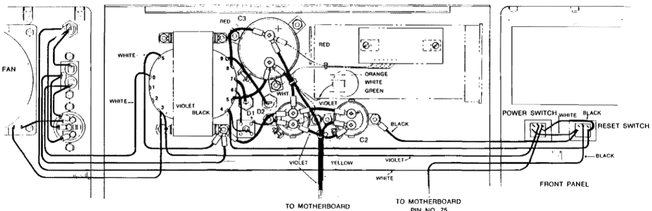
FIGURES-POWER SUPPLY WIRING
MINI FLOPPY DRIVE (OPTION)
VIOLET YELLOW
~
TO MOTHERBOARD
VIOLET
WHITE
TO MOTHERBOARD PIN NO. 75
FIGURE 4 - FRONT PANEL WIRING
(CT .~J
RESET SWITCH