Volume 2010, Article ID 181403,9pages doi:10.1155/2010/181403
Research Article
Particle Filtering: The Need for Speed
Gustaf Hendeby,
1Rickard Karlsson,
2and Fredrik Gustafsson (EURASIP Member)
3 1Department of Augmented Vision, German Research Center for Artificial Intelligence,67663 Kaiserslatern, Germany
2NIRA Dynamics AB, Teknikringen 6, 58330 Link¨oping, Sweden
3Department of Electrical Engineering, Link¨oping University, 58183 Link¨oping, Sweden
Correspondence should be addressed to Rickard Karlsson,[email protected]
Received 22 February 2010; Accepted 26 May 2010
Academic Editor: Abdelak Zoubir
Copyright © 2010 Gustaf Hendeby et al. This is an open access article distributed under the Creative Commons Attribution License, which permits unrestricted use, distribution, and reproduction in any medium, provided the original work is properly cited.
Theparticle filter(PF) has during the last decade been proposed for a wide range of localization and tracking applications. There is a general need in such embedded system to have a platform for efficient and scalable implementation of the PF. One such platform is thegraphics processing unit(GPU), originally aimed to be used for fast rendering of graphics. To achieve this, GPUs are equipped with a parallel architecture which can be exploited forgeneral-purpose computingon GPU (GPGPU) as a complement to the central processing unit (CPU). In this paper, GPGPU techniques are used to make a parallel recursive Bayesian estimation implementation using particle filters. The modifications made to obtain a parallel particle filter, especially for the resampling step, are discussed and the performance of the resulting GPU implementation is compared to the one achieved with a traditional CPU implementation. The comparison is made using a minimal sensor network with bearings-only sensors. The resulting GPU filter, which is the first complete GPU implementation of a PF published to this date, is faster than the CPU filter when many particles are used, maintaining the same accuracy. The parallelization utilizes ideas that can be applicable for other applications.
1. Introduction
The signal processing community has for a long time been relying on Moore’s law, which in short says that the computer capacity doubles for each 18 months. This technological evo-lution has been possible by down-scaling electronics where the number of transistors has doubled every 18 months, which in turn has enabled more sophisticated instructions and an increase in clock frequency. The industry has now reached a phase where the power and heating problems have become limiting factors. The increase in processing speed of the CPU (central processing unit) has been exponential since the first microprocessor was introduced in 1971 and in total it has increased one million times since then. However, this trend stalled a couple of years ago. The new trend is to double the number of cores in CMP (chip multicore processing), and the number of cores is expected to follow Moore’s law for the next ten years [1]. The software community is now looking for new programming tools to utilize the parallelism
of CMPs, which is not an easy task [2]. The signal processing community has also started to focus more on distributed and parallel implementations of the core algorithms.
In this contribution, the focus is on distributedparticle filter(PF) implementations. The particle filter has since its introduction in its modern form [3] turned into a standard algorithm for nonlinear filtering, and is thus a working horse in many current and future applications. The particle filter is sometimes believed to be trivially parallelizable, since each core can be responsible for the operations associated with one or more particles. This is true for the most characteristic steps in the PF algorithm applied to each particle, but not for the interaction steps. Further, as is perhaps less well known, the bottle neck computation even on CPU’s is often not the particle operations but the resampling [4], and this is not obvious to parallelize, but possible.
(i) Initialization: each particle is sampled from a given initial distribution and the weights are initialized to a constant; parallelizable and thusO(1).
(ii) Measurement update: the likelihood of the obser-vation is computed conditional on the particle; parallelizable and thusO(1).
(iii) Weight normalization: the sum of the weight is needed for normalization. A hierarchical evaluation of the sum is possible, which leads to complexity
O(log(N)).
(iv) Estimation: the weighted mean is computed. This requires interaction. Again, a hierarchical sum eval-uation leads to complexityO(log(N)).
(v) Resampling: this step first requires explicitly or implicitly acumulative distribution function(CDF) to be computed from the weights. There are different ways to solve this, but it is not obvious how to parallelize it. It is possible to make this aO(log(N)) operation. There are other interaction steps here commented on in more detail later on.
(vi) Prediction: each particle is propagated through a common proposal density, parallelizable and thus
O(1).
(vii) Optional steps of Rao-Blackwellization: if the model has a linear Gaussian substructure, part of the state vector can be updated with the Kalman filter. This is done locally for each particle, and thusO(1).
(viii) Optional step of computing marginal distribution of the state (the filter solution) rather than the state trajectory distribution. This isO(N2) on a single core processor, but parallelizable toO(N). It also requires massive communication between the particles.
This suggests the following basic functions of complexity for the extreme cases single core, M = 1, and complete parallelization,M/N → 1:
Single-core :f1(N)=c1+c2N,
Multicore
M
N −→1
:fM(N)=c3+c4log(N). (1)
For a fixed number of particles and sufficiently large number of cores the parallel implementation will always be more efficient. In the future, we might be able to useN = M. However, for the N that the application requires, the best solution depends on the constants. One can here define a break-even number
N=sol
N
f1(N)= fM(N)
. (2)
This number depends on the relative processing speed of the single and multicore processors, but also on how efficient the implementation is.
It is the purpose of this contribution to discuss these important issues in more detail, with a focus on general purpose graphical processing units(GPGPUs). We also provide
Table1: Table describing how the number of pipelines in the GPU has changed. (The latest generation of graphics cards form the two main manufacturers, NVIDIA, and ATI, have unified shaders instead of specialized ones. These are marked with†.)
Model Vertex pipes Frag. pipes Year NVIDIA GeForce 6800 Ultra 6 16 2004 ATI Radeon X850 XT PE 6 16 2005 NVIDIA Geforce 7900 GTX 8 24 2006 NVIDIA Geforce 7950 GX2 16 48 2006 ATI Radeon X1900 XTX 8 48 2006 NVIDIA GeForce 8800 Ultra 128† 128† 2007 ATI Radeon HD 2900 XT 320† 320† 2007 NVIDIA GeForce 9800 GTX+ 128† 128† 2008 ATI Radeon HD 4870 X2 2×800† 2×800† 2008 NVIDIA GeForce 9800 GT2 2×128† 2×128† 2008 NVIDIA GeForce 295 GTX 2×240† 2×240† 2009 ATI Radeon HD 5870 1600† 1600† 2009 NVIDIA GeForce 380 GTX 512† 512† 2009
the first complete GPGPU implementations of the PF, and use this example as a ground for a discussion ofN.
Multicore implementations of the PF has only recently been studied. For instance, [5] presents a GPU PF for visual 2d tracking, [6] focusing on doing parallel resampling on a FPGA, and [7,8] relating to this work. To the best of the authors’ knowledge no successful complete implementation of a general PF algorithm on a GPU has previously been reported.
The organization is as follows. Since parallel program-ming may be unfamiliar to many researchers in the signal processing community, we start with a brief tutorial in Section 2, where background material for parallel program-ming, particularly using the graphics card, is reviewed. In Section 3recursive Bayesian estimation utilizing the particle filter is presented for a GPU implementation. InSection 4 a simulation study is presented comparing CPU and GPU performance. Finally,Section 5summarizes the results.
2. Parallel Programming
Nowadays, there are many types of parallel hardware available; examples include multicore processors, field-programmable gate arrays(FPGAs), computer clusters, and GPUs. GPUs offer low-cost and easily accessible single instruction multiple data(SIMD) parallel hardware—almost every new computer comes with a decent graphics card. Hence, GPUs are an interesting option not only for speeding up algorithms but also for testing parallel implementations.
Vertex data
Vertex
processor Rasterizer Fragmentprocessor buFrameffer(s) Textures
Figure1: The graphics pipeline. The vertex and fragment proces-sors can be programmed with user code which will be evaluated in parallel on several pipelines. In the latest GPUs these shaders are unified instead of specialized as depicted.
2.1. Graphics Hardware. Graphics cards are designed to pri-marily produce graphics, which makes their design different from general purpose hardware, such as the CPU. One such difference is that GPUs are designed to handle huge amounts of data about an often complex scene in real time. To achieve this, the GPU is equipped with a SIMD parallel instruction set architecture. The GPU is designed around the standardized graphics pipeline [11] depicted inFigure 1. It consists of three processing steps, which all have their own purpose when it comes to producing graphics, and some dedicated memory units. From having predetermined functionality, GPUs have moved towards providing more freedom for the programmer. Graphics cards allow for customized code in two out of the three computational units: the vertex shader and the fragment shader (these two steps can also be unified in one shader). As a side-effect, general-purpose computing on graphics processing units(GPGPUs) has emerged to utilize this new source of computational power [11–13]. For highly parallelizable algorithms the GPU may outperform the sequential CPU.
2.2. Programming the GPU. The two programmable steps in the graphics pipeline are the vertex processor and the fragment processor, or if these are unified. Both these processors can be controlled with programs calledshaders. Shaders, or GPU programs, were introduced to replace fixed functionality in the graphics pipeline with more flexible programmable processors.
Some prominent differences between regular program-ming and GPU programprogram-ming are the basic data types which are available, colors and textures. In newer generations of GPUs 32 bit floating point operations are supported, but the rounding units do not fully conform to the IEEE floating point standard, hence providing somewhat poorer numerical accuracy. Internally the GPU works with quadruples of floating point numbers that represent colors (red, green, blue, and alpha) and data is passed to the GPU astextures. Textures are intended to be pictures that are mapped onto surfaces given by the vertices.
In order to use the GPU for general purpose calculations, a typical GPGPU application has a program structure similar toFigure 2.
Initialize GPU
Upload program Upload suitable shader code to
vertex and fragment shaders
Upload data Upload textures containing the data to be processed to the GPU
Run program Draw a rectangle covering as many pixels as there are parallel computations to do
Download data Download the result from the render buffer to the CPU
Figure2: Work flow for GPGPU programming using theOpenGL shading language(GLSL).
2.3. GPU Programming Language. There are various ways to access the GPU resources as a programmer. Some of the available alternatives are
(i) OpenGL [14] using the OpenGL Shading Language (GLSL) [15],
(ii)C for graphics(Cg) [16],
(iii) DirectX High-Level Shader Language (HLSL) [17], (iv) CUDA [18] if using a NVIDIA graphics card.
Short descriptions of the alternatives are given in [8], and more information about these and other alternatives can be found in [11, 13, 16]. CUDA presents the user with a C language for direct application development on NVIDIA GPUs.
The development in this paper has been conducted using GLSL.
3. A GPU Particle Filter
PF applied to a lowdimensional state vector, where a KF is attached to each particle enabling efficient and real-time implementations. Still, both the PF and RBPF are computer intensive algorithms requiring powerful processors.
3.2. The Particle Filter Algorithm. The general nonlinear filtering problem is to estimate the state,xt, of a state-space
system
xt+1= f(xt,wt),
yt=h(xt) +et,
(3)
where yt is the measurement and wt ∼ pw(wt) and et ∼ pe(et) are the process and measurement noise, respectively.
The function f describes the dynamics of the system, h
the measurements, and pw and pe are probability density
functions (PDFs) of the involved noise. For the important special case of linear-Gaussian dynamics and linear-Gaussian observations the Kalman filter [24,30] solves the estimation problem in an optimal way. A more general solution is the particle filter(PF) [3,31,32] which approximately solves the Bayesian inference for the posterior state distribution [33] given by
p(xt+1|Yt)=
p(xt+1|xt)p(xt|Yt)dxt,
p(xt|Yt)= p
yt|xt
p(xt|Yt−1) pyt|Yt−1
,
(4)
whereYt= {yi}t
i=1is the set of available measurements. The PF uses statistical methods to approximate the integrals. The basic PF algorithm is given inAlgorithm 1.
To implement a parallel particle filter on a GPU there are several aspects ofAlgorithm 1that require special attention. Resampling is the most challenging step to implement in parallel since all particles and their weights interact with each other. The main difficulties are cumulative summation, and selection and redistribution of particles. In the following sections, solutions suitable for parallel implementation are proposed for these tasks. Another important issue is how random numbers are generated, since this can consume a substantial part of the time spent in the particle filter. The remaining steps, likelihood evaluation as part of the measurement update and state propagation as part of the time update, are only briefly discussed since they are parallel in their nature.
The resulting parallel GPU implementation is illustrated in Figure 3. The steps are discussed in more detail in this section.
3.3. GPU PF: Random Number Generation. State-of-the-art graphics cards do not have sufficient support for random number generation for direct usage in a particle filter, since the statistical properties of the built-in generators are too poor.
The algorithm in this paper therefore relies on random numbers generated on the CPU to be passed to the GPU. This introduces substantial data transfer, as several random
(1) Lett:=0, generateNparticles:{x0(i)}Ni=1∼p(x0).
(2) Measurement update: Compute the particle weights
ωt(i)=p(yt|xt(i))/ Nj=1p(yt|x
(j)
t ).
(3) Resample:
(a) GenerateNuniform random numbers
{u(ti)}Ni=1∼U(0, 1).
(b) Compute the cumulative weights:
c(ti)= ij=1ω (j)
t .
(c) GenerateNnew particles usingu(ti)andc(ti): {x(ti+)}Ni=1where Pr(x
(i)
t+=x (j(i))
t )=ω
(j(i))
t .
(4) Time update:
(a) Generate process noise{w(ti)}iN=1∼pw(wt).
(b) Simulate new particlesxt(+1i) =f(xt(+i),wt(i)).
(5) Lett:=t+ 1 and repeat from 2.
Algorithm1: The Particle Filter [3].
numbers per particle are needed in each iteration of the particle filter. Uploading data to the graphics card is rather quick, but performance is still lost. Furthermore, this makes generation of random numbers aO(N) operation instead of aO(1) operation, as would be the case if the generation was completely parallel.
Generating random numbers on the GPU suitable for use in Monte Carlo simulations is an ongoing research topic, see, for example, [34–36]. Implementing the random number generation in the GPU will not only reduce data transfer and allow for a standalone GPU implementation, an efficient parallel version will also improve the overall performance as the random number generation itself takes a considerable amount of time.
3.4. GPU PF: Likelihood Evaluation and State Propagation. Both likelihood evaluation (as part of the measurement update) and state propagation (in the time update) of Algorithm 1, can be implemented straightforwardly in a parallel fashion since all particles are handled independently. Consequently, both operations can be performed in O(1) time with N parallel processors, that is, one processing element per particle. To solve new filtering problems, only these two functions have to be modified. As no parallelization issues need to be addressed, this is easily accomplished. In the presented GPU implementation the particles x(i) and the weights ω(i) are stored in separate textures which are updated by the state propagation and the likelihood evaluation, respectively. One texture can only hold four-dimensional state vectors in a natural way, but using multiple rendering targets the state vectors can be extended when needed without any major changes to the code. The idea is then to store the state in several textures. For instance, with two textures to store the state, the state vector can grow to eight states. With the multitarget capability of modern graphics cards the changes needed are minimal.
Measurement update
Resampling
Time update
yt
u(i)t
ωt(i)
t=iω(i)t
ω(i)t =ω(i)t /t
x(i)t+=x(j (i)) t
c(i)t =ij=1ω(j)t
ω(i)t =p(yt|xt(i))ω(i)t
j(i)=P−1(u(i))
x(i)t+1=f(x(i)t+,ω(i)t )
Figure3: GPU PF algorithm. The outer boxes make up the CPU program starting the inner boxes on the GPU in correct order. The figure also indicates what is fed to the GPU; remaining data is generated on it.
uniform vec2 y;
uniform sampler2Dx,w, pdf;
uniform mat2 sqrtSigmainv;
const vec2 S1=vec2(1., 0); const vec2 S2=vec2(-1., 0); void main(void)
{
vec2 xtmp=texture2D(x, g1 TexCoord[0]. st ).xy;
vec2 e=y-vec2(distance(xtmp,S1), distance (xtmp,S2));
e=sqrtSigmainv∗e +vec2(.5,.5); g1 FragColor.x=texture2D(pdf,e).x
∗ texture2D(w, g1 Texcoord[0].st).x;
}
Listing1: GLSL coded fragment shader: measurement update.
texture) the likelihood computations can be replaced by fast texture lookups utilizing the fast texture interpolation. The result is not as exact as if the likelihood was computed the regular way, but the increase in speed is often considerable.
Furthermore, as discussed above, the state propagation uses externally generated process noise, but it would also be possible to generate the random numbers on the GPU.
Example(Shader program). To exemplify GLSL source code, Listing1contains the code needed for a measurement update in the range-only measurement example inSection 4.
1 + 2=3 3 + 4=7
3 + 7=10
3
3=10−7 10
10
F
o
rwar
d
adder
B
ackwar
d
adder
Original data Cumulative sum
1 2 3 4 1=3−2 6=10−410
Figure4: A parallel implementation of cumulative sum generation of the numbers 1, 2, 3, and 4. First the sum, 10, is calculated using a forward adder tree. Then the partial summation results are used by the backward adder to construct the cumulative sum; 1, 3, 6, and 10.
The code is very similar to C code, and is executed once for each particle, that is, fragment. To run the program a rectangle is fed as vertices to the graphics card. The size of the rectangle is chosen such that there will be exactly one fragment per particle, and that way the code is executed once for every particle.
The keyworduniformindicates that the following vari-able is set by the API before the program is executed. The variable yis hence a two-component vector,vec2, with the measurement, and S1 and S2 contain the locations of the sensors. Variables of the type sampler2D are pointers to specific texture units, and hencexandwpoint out particles and weights, respectively, and pdf the location of the lookup table for the measurement likelihood.
The first line of code makes a texture lookup and retrieves the state, stored as the two first components of the vector (color data) as indicated by the xy suffix. The next line computes the difference between the measurement and the predicted measurement, before the error is scaled and shifted to allow for a quick texture look up. The final line writes the new weight to the output.
3.5. GPU PF: Summation. Summation is part of the weight normalization (as the last step of the measurement update) and the cumulative weight calculation (during resampling) of Algorithm 1. A cumulative sum can be implemented using a multipass scheme, where an adder tree is run forward and then backward, as illustrated inFigure 4. This multipass scheme is a standard method for parallelizing seemingly sequential algorithms based on the scatter and gather principles. In [11], these concepts are described in the GPU setting. In the forward pass partial sums are created that are used in the backward pass to compute the missing partial sums to complete the cumulative sum. The resulting algorithm isO(logN) in time givenNparallel processors and
Nparticles.
3.6. GPU PF: Resampling. To prevent sample impoverish-ment, the resampling step ofAlgorithm 1replaces unlikely particles with likelier ones. This is done by drawing a new set of particles {x(+i)} with replacement from the original particles {x(i)} in such a way that Pr(x(i)
x(1) x(2) x(3) x(4) x(5) x(6) x(7) x(8)
x(j)+ 0
1
u
(
k
)
Figure5: Particle selection by comparing uniform random num-bers (•) to the cumulative sum of particle weights (–).
0 1 2 3 4 5 6 7 8
x(2) x(4) x(5) x(5) x(5) x(7) x(7) x(7)
x(i)+ =
p(1) p
(2)
p(3) p
(4) p(5)
p(6) p
(7)
p(8)
Vertices
Fragments
Rast
er
iz
e
x(2) x(4) x(5) x(7)
k:
p(0)
Figure6: Particle selection on the GPU. The line segments are made up by the pointsN(i−1)andN(i), which define a line where every
segment represents a particle. Some line segments have length 0, that is, no particle should be selected from them. The rasterizer creates particlesxaccording to the length of the line segments. The line segments in this figure match the situation inFigure 5.
using uniformly distributed random numbers as input to the inverse CDF given by the particle weights
x(ti+)=x (j(i))
t , with j(i)=P−1
u(j(i))
, (5)
wherePis the CDF given by the particle weights.
The idea for the GPU implementation is to use the rasterizer to do stratified resampling. Stratified resampling is especially suitable for parallel implementation because it produces ordered random numbers, and guarantees that if the interval (0, 1] is divided intoN intervals, there will be exactly one random number in each subinterval of length
N−1. Selecting which particles to keep is done by drawing a line. The line consists of one line segment for each particle in the original set, indicated by its color, and where the length of the segments indicate how many times the particles should be replicated. With appropriate segments, the rastering will create evenly spaced fragments from the line, hence giving more fragments from long line segments and consequently more particles of likelier particles. The properties of the stratified resampling are perfect for this. They make it possible to compute how many particles have been selected once a certain point in the original distribution was selected. The expression for this is
N(i)=Nc(i)−u(Nc(i))
, (6)
where N is the total number of particles, c(i) = i j=1ω(j) is the ith cumulative weight sum, and N(i) the number of particles selected when reaching the ith particle in the
y1 y2
x
S1 S2
Figure7: A range-only sensor system, with 2D-position sensors in
S1andS2with indicated range resolution.
100 102 104 106 108 10−1
100 101 102 103 104 105
Number of particles
T
ime
(s)
GPU CPU
Figure8: Comparison of time used for GPU and CPU.
original set. The expression for stratified resampling is vital for parallelizing the resampling step, and hence to make a GPU implementation possible. By drawing the line segment for particleifromN(i−1)toN(i), withN(0)=0, the particles that should survive the resampling step correspond to a line segment as long as the number of copies there should be in the new set. Particles which should not be selected get line segments of zero length. Rastering with unit length between the fragments will therefore produce the correct set of resampled particles, as illustrated in Figure 6for the weights inFigure 5. The computational complexity of this is O(1) withN parallel processors, as the vertex positions can be calculated independently. Unfortunately, the used generation of GPUs has a maximal texture size limiting the number of particles that can be resampled as a single unit. To solve this, multiple subsets of particles are simultaneously being resampled and then redistributed into different sets, similarly to what is described in [38]. This modification of the resampling step does not seem to significantly affect the performance of the particle filter as a whole.
16 256 4096 65536 1048576 0
10 20 30 40 50 60 70 80 90 100
Number of particles
T
ime
spent
(%)
Estimate
Time update
Resample Random numbers Measurement update
(a) GPU
16 256 4096 65536 1048576 0
10 20 30 40 50 60 70 80 90 100
Number of particles
T
ime
spent
(%)
Estimate
Time update
Resample Random numbers Measurement update
(b) CPU
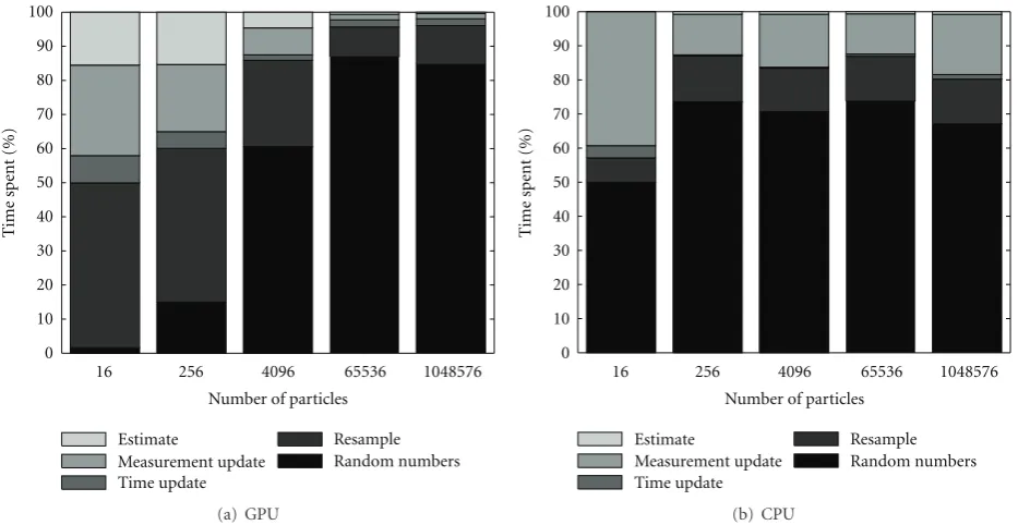
Figure9: Comparison of the relative time spent in the different steps particle filter, in the GPU and CPU implementation, respectively.
time complexity of the algorithm,O(logN) for the parallel algorithm compared toO(N) for a sequential algorithm.
The analysis of the algorithm complexity above assumes that there are as many parallel processors as there are particles in the particle filter, that is, N parallel elements. Today this is a bit too optimistic, there are hundreds of parallel pipelines in a modern GPU, hence much less than the typical number of particles. However, the number of parallel units is constantly increasing.
Especially the cumulative sum suffers from a low degree of parallelization. With full parallelization the time com-plexity of the operation is O(logN) whereas a sequential algorithm is O(N), however the parallel implementation usesO(2N) operations in total. That is, the parallel imple-mentation uses about twice as many operations as the sequential implementation. This is the price to pay for the parallelization, but is of less interest as the extra operations are shared between many processors. As a result, with few pipelines and many particles the parallel implementation will have the same complexity as the sequential one, roughly
O(N/M) whereMis the number of processors.
4. Simulations
Consider the following range-only application as depicted in Figure 7. The following state-space model represents the 2D-position
xt+1=xt+wt,
yt=h(xt) +et=
⎛
⎝xt−S12
xt−S22 ⎞
⎠+et, (7)
Table2: Hardware used for the evaluation.
GPU CPU
Model: NVIDIA GeFORCE
7900 GTX Model:
Intel Xeon 5130 Driver: 2.1.2 NVIDIA 169.09 Clock speed: 2.0 GHz
Bus: PCI Express,
14.4 GB/s Memory: 2.0 GB Clock
speed: 650 MHz OS:
CentOS 5.1,
Processors: (vertex/fragment)8/24 (Linux)64 bit
whereS1andS2are sensor locations andxtcontains the
2D-position of the object. This could be seen as a central node in a small sensor network of two nodes, which easily can be expanded to more nodes.
To verify the correctness of the implementation a particle filter, using the exact same resampling scheme, has been designed for the GPU and the CPU. The resulting filters give practically identical results, though minor differences exist due to the less sophisticated rounding unit available in the GPU and the trick in computing the measurement likelihood. Furthermore, the performance of the filters is comparable to what has been achieved previously for this problem.
(Note that 16 particles are not enough for this problem, nor is as many as 106needed. However, the large range shows the complexity better.)
Some observations: for few particles the overhead from initializing and using the GPU is large and hence the CPU implementation is the fastest. With more work optimizing the parallel implementation the gap could be reduced. The CPU complexity follows a linear trend, whereas at first the GPU time hardly increases when using more particles; parallelization pays off. For even more particles there are not enough parallel processing units available and the complexity becomes linear, but the GPU implementation is still faster than the CPU. Note that the particle selection is performed on 8 processors and the other steps on 24, seeTable 2, and hence that the degree of parallelization is not very high with many particles.
A further analysis of the time spent in the GPU imple-mentation shows which parts are the most time consuming, see Figure 9. The main cost in the GPU implementation quickly becomes the random number generation (performed on the CPU), which shows that if that step can be parallelized there is much to gain in performance. For both CPU and GPU the time update step is almost negligible, which is an effect of the simple dynamic model. The GPU would have gained from a computationally expensive time update step, where the parallelization would have paied offbetter. To produce an estimate from the GPU is relatively more expensive than it is with the CPU. For the CPU all steps are
O(N) whereas for the GPU the estimate isO(logN) where both the measurement update and the time update steps are O(1). Not counting the random number generation, the major part of the time is spent on resampling in the GPU, whereas the measurement update is a much more prominent step in the CPU implementation. One reason is the implemented hardware texture lookups for the measurement likelihood in the GPU.
5. Conclusions
In this paper, the first complete parallel general particle filter implementation in literature on a GPU is described. Using simulations, the parallel GPU implementation is shown to outperform a CPU implementation when it comes to computation speed for many particles while maintaining the same filter quality. As the number of pipelines steadily increases, and can be expected to match the number of particles needed for some low-dimensional problems, the GPU is an interesting alternative platform for PF implemen-tations. The techniques and solutions used in deriving the implementation can also be used to implement particle filters on other similar parallel architectures.
References
[1] M. D. Hill and M. R. Marty, “Amdahl’s law in the multicore era,”Computer, vol. 41, no. 7, pp. 33–38, 2008.
[2] S. Borkar, “Thousand core chips: a technology perspective,” in Proceedings of the 44th ACM/IEEE Design Automation Conference (DAC’07), pp. 746–749, June 2007.
[3] N. J. Gordon, D. J. Salmond, and A. F. M. Smith, “Novel approach to nonlinear/non-Gaussian Bayesian state estima-tion,”IEE Proceedings, Part F, vol. 140, no. 2, pp. 107–113, 1993.
[4] F. Gustafsson, “Particle filter theory and practice with positioning applications,” to appear in IEEE Aerospace and Electronic Systems, magazine vol. 25, no. 7 july 2010 part 2: tutorials.
[5] A. S. Montemayor, J. J. Pantrigo, A. S´anchez, and F. Fern´andez, “Particle filter on GPUs for real time tracking,” inProceedings of the International Conference on Computer Graphics and Interactive Techniques (SIGGRAPH ’04), p. 94, Los Angeles, Calif, USA, August 2004.
[6] S. Maskell, B. Alun-Jones, and M. Macleod, “A single instruction multiple data particle filter,” in Proceedings of Nonlinear Statistical Signal Processing Workshop (NSSPW ’06), Cambridge, UK, September 2006.
[7] G. Hendeby, J. D. Hol, R. Karlsson, and F. Gustafsson, “A graphics processing unit implementation of the particle filter,” inProceedings of the 15th European Statistical Signal Processing Conference (EUSIPCO ’07), pp. 1639–1643, Pozna ´n, Poland, September 2007.
[8] G. Hendeby,Performance and implementation aspects of non-linear filtering, Ph.D. thesis, Link¨oping Studies in Science and Technology, March 2008.
[9] “MAGMA,” 2009,http://icl.cs.utk.edu/magma/.
[10] “NVIDIA CUDA applications browser,” 2009, http://www .nvidia.com/content/cudazone/CUDABrowser/assets/data/ applications.xml.
[11] M. Pharr, Ed., GPU Gems 2. Programming Techniques for High-Performance Graphics and General-Purpose Computa-tion, Addison-Wesley, Reading, Mass, USA, 2005.
[12] M. D. Mccool, “Signal processing and general-purpose com-puting and GPUs,”IEEE Signal Processing Magazine, vol. 24, no. 3, pp. 110–115, 2007.
[13] “GPGPU programming,” 2006,http://www.gpgpu.org/. [14] D. Shreiner, M. Woo, J. Neider, and T. Davis,OpenGL
Pro-gramming Language. The Official Guide to learning OpenGL, Version 2, Addison-Wesley, Reading, Mass, USA, 5th edition, 2005.
[15] R. J. Rost,OpenGL Shading Language, Addison-Wesley, Read-ing, Mass, USA, 2nd edition, 2006.
[16] “NVIDIA developer,” 2006,http://developer.nvidia.com/. [17] M. Corporation, “High-level shader language. In DirectX 9.0
graphics,” 2008,http://msdn.microsoft.com/directx.
[18] “CUDA zone—learn about CUDA,” 2009,
http://www.nvidia.com/object/cuda what is.html.
[19] Y. Zou and K. Chakrabarty, “Distributed mobility manage-ment for target tracking in mobile sensor networks,” IEEE Transactions on Mobile Computing, vol. 6, no. 8, pp. 872–887, 2007.
[20] R. Huang and G. V. Z´aruba, “Incorporating data from multi-ple sensors for localizing nodes in mobile ad hoc networks,”
IEEE Transactions on Mobile Computing, vol. 6, no. 9, pp. 1090–1104, 2007.
[21] L. Mihaylova, D. Angelova, S. Honary, D. R. Bull, C. N. Canagarajah, and B. Ristic, “Mobility tracking in cellular net-works using particle filtering,”IEEE Transactions on Wireless Communications, vol. 6, no. 10, pp. 3589–3599, 2007. [22] X. Chai and Q. Yang, “Reducing the calibration effort for
probabilistic indoor location estimation,”IEEE Transactions on Mobile Computing, vol. 6, no. 6, pp. 649–662, 2007. [23] M. Montemerlo, S. Thrun, D. Koller, and B. Wegbreit,
simultaneous localization and mapping that provably con-verges,” inProceedings of the 18th International Joint Conference on Artificial Intelligence, pp. 1151–1157, Acapulco, Mexico, August 2003.
[24] R. E. Kalman, “A new approach to linear filtering and prediction problems,”Journal of Basic Engineering, vol. 82, pp. 35–45, 1960.
[25] Y. Bar-Shalom and X. R. Li,Estimation and Tracking: Princi-ples, Techniques, and Software, Artech House, Boston, Mass, USA, 1993.
[26] B. D. O. Anderson and J. B. Moore,Optimal Filtering, Prentice-Hall, Englewood Cliffs, NJ, USA, 1979.
[27] F. Gustafsson, F. Gunnarsson, N. Bergman et al., “Particle filters for positioning, navigation, and tracking,”IEEE Trans-actions on Signal Processing, vol. 50, no. 2, pp. 425–437, 2002. [28] R. Chen and J. S. Liu, “Mixture Kalman filters,”Journal of the
Royal Statistical Society. Series B, vol. 62, no. 3, pp. 493–508, 2000.
[29] T. Sch¨on, F. Gustafsson, and P.-J. Nordlund, “Marginalized particle filters for mixed linear/nonlinear state-space models,”
IEEE Transactions on Signal Processing, vol. 53, no. 7, pp. 2279– 2289, 2005.
[30] T. Kailath, A. H. Sayed, and B. Hassibi,Linear Estimation, Prentice-Hall, Englewood Cliffs, NJ, USA, 2000.
[31] A. Doucet, N. de Freitas, and N. Gordon, Eds., Sequential Monte Carlo Methods in Practice, Statistics for Engineering and Information Science, Springer, New York, NY, USA, 2001. [32] B. Ristic, S. Arulampalam, and N. Gordon,Beyond the Kalman
Filter: Particle Filters for Tracking Applications, Artech House, Boston, Mass, USA, 2004.
[33] A. H. Jazwinski,Stochastic Processes and Filtering Theory, vol. 64 ofMathematics in Science and Engineering, Academic Press, New York, NY, USA, 1970.
[34] A. De Matteis and S. Pagnutti, “Parallelization of random number generators and long-range correlations,”Numerische Mathematik, vol. 53, no. 5, pp. 595–608, 1988.
[35] C. J. K. Tan, “The PLFG parallel pseudo-random number generator,”Future Generation Computer Systems, vol. 18, no. 5, pp. 693–698, 2002.
[36] M. Sussman, W. Crutchfield, and M. Papakipos, “Pseudo-random number generation on the GPU,” inProceedings of the 21st ACM SIGGRAPH/Eurographics Symposium Graphics Hardware, pp. 87–94, Vienna, Austria, September 2006. [37] G. Kitagawa, “Monte Carlo filter and smoother for
non-Gaussian nonlinear state space models,”Journal of Computa-tional and Graphical Statistics, vol. 5, no. 1, pp. 1–25, 1996. [38] M. Boli´c, P. M. Djuri´c, and S. Hong, “Resampling algorithms