7 doi: 10.32622/ijrat.82202007
Abstract— The new configuration of the conventional (existing) three phase transfer field reluctance machine is intended to minimize the excessive leakage reactance associated with the quadrature axis reactance of the machine, due to salient nature of its rotor poles structure.
This is achieved by optimizing the rotor design, through the introduction of cage (rotor) windings at the periphery of the shaft of the machine sections (M/C A and M/C B). The idea is that when windings are wounded on the rotor sections of the machine, resistance is added to the rotor circuit, the rotor power factor is improved, which in turn results in improved output torque. This of course increases the rotor impedance and therefore decreases the value of rotor circuit. Consequently, the effect of improved power factor predominates and the starting torque is increased. To cushion the effect such reduction in induced rotor current, the auxiliary and rotor (cage) windings of both machines sections are connected in parallel but transposed between the two machine halves and short circuited.
Index Terms- Auxiliary windings, Cage (rotor) windings, induced rotor current, main windings, resultant impedance.
I. INTRODUCTION
The scale or yard-stick upon which every electric motor is measured is principally the nature of its output characteristics. Hence, the consistence research on the improvement of motor output characteristics, which includes output power, electromagnetic torque, power factor, efficiency etc becomes pertinent. The output of all plain transfer field effect machines would be less than that of a conventional induction machine of comparable size and rating. This is the attribute of their low direct axis reactance to quadrature axis reactance ratio, accompanied with excessive leakage reactance (Agu L.A, 1984). An analysis on improvement in this disorderliness is the subject matter of this novel.
Manuscript revised on March 16, 2020 and published on March 25, 2020
Obute K. C., Department of Electrical Engineering, Nnamdi Azikiwe
University, Awka, Anambra State, Nigeria.
Olufolahan Oduyemi, Department of Engineering and Technology, South
East Missouri State University, Cape Giradeau, Missouri MO63701, USA
Eze, E C., Department of Electronics and Computer Engineering, Nnamdi
Azikiwe University, Awka.
Okonkwo, M. C., Department of Electrical Engineering, Nnamdi Azikiwe
University, Awka, Anambra State, Nigeria.
II. THE MACHINE DESCRIPTION
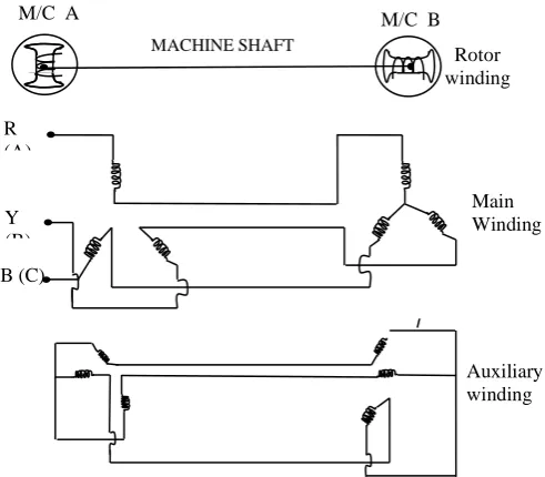
[image:1.595.310.556.511.726.2]The structural arrangement of the machine under study is shown in figure 1. Unlike the existing three phase transfer field cage –less machine counterpart (Agu L.A, Anih L.U 2002), the three-phase transfer field machine with cage windings comprise two identical poly-phase reluctance machine with moving conductors (rotor windings), whose salient poles rotor are mechanically coupled together, such that their d and q axes are in space quadrature. As depicted in figure 1, the stator (primary) windings, are integrally wound. Each machine element has three sets of windings. Both sets of windings are identical. The main and auxiliary windings are housed in the stators slots. The main windings of the machine carry the excitation current, while the auxiliary and the rotor windings, carry the circulating current. The (2s-1) ω0 low frequency current is confined in the auxiliary and rotor windings without interfering with the supply. The main windings of the machine sets are connected in series while the auxiliary windings, though also in the stator are transposed between the two machine stacks. They are wound for the same pole number and both are star connected. The third set of windings known as the rotor (cage) windings are wounded at the periphery of the rotor shaft connecting the two machine sets. Just as in the auxiliary windings, the rotor (cage) windings are also transposed between the two machine stacks and then connected in parallel with the auxiliary windings (see figure 2).
Figure 1: Connection diagram for three phase transfer field reluctance machine with rotor (cage) winding
Dynamic State Performance Analysis of Three Phase
Transfer Field Machine with Rotor (CAGE) Windings
Obute K. C., Olufolahan Oduyemi, Eze, E C.
Main Winding Auxiliary winding R (A) Y (B) B (C)
M/C B M/C A
Rotor winding
8 III. DYNAMIC MODEL OF 3-PHASE TRANSFER FIELD
MACHINE WITH CAGE (ROTOR)WINDINGS
For us to derive the dynamic equations of the circuit model of 3-Phase transfer Field Machine with cage (rotor) windings, it is paramount to take a look at the variation of inductances with rotor position since the rotor has salient poles. In general, the peameance along the d and q axes is not the same.
Since the rotor is of salient poles, its mmfs are always directed along the d and q axes. Also, the direction of the resultant mmf of the stator windings relative to these two axes will vary with the power factor. A common approach to handling the magnetic effect of the stator’s resultant mmf is to resolve it along the d and q axes, where it could be dealt with systematically. Let us consider the magnetic effect of current flowing in phase a of the stator. The resolved components of the a-phase mmf Fa, will produce the flux
components;
d = Pd Fa sin θr and q = Pq Fa cos θr along the d and q axes
respectively.
Where P = peameance
The linkage of these resolved flux components with the a-phase windings is;
λaa = Ns ( d Sin θr + q cos θr) Wb turn. = Ns Fa (Pd sin2θr + Pq cos2θr) = Ns Fa ( - cos 2θr) (1)
Similarly, the linkage of the flux component, d and q by the b - phase winding that is ahead may be written as: λba = Ns Fa (Pd sin θr sin (θr - ) + pq cos θr cos (θr - )) = Ns Fa ( - cos 2(θr - )) (2)
Based on the functional relationship of λaa with the rotor angle, θr, we can deduce that the self inductance of the stator a-phase winding, excluding the leakage has the form;
Laa = Lo – Lms cos 2 θr H
Where; Lo = and Lms =
Those of the b – and c – phases, Lbb, Lcc are similar to that of Laa but with θr replaced by (θr - ) and (θr+ ), respectively. Similarly, it can be deduced that the mutual inductance between the a and b phase of the stator is of the form, Lab = Lba = - Lms cos 2 (θr - ) H (3)
Similarly, expression for Lbc and Lac can be obtained by replacing θr with (θr - ) and (θr+ ) respectively.
Since a conventional (existing) transfer field effect machine is composed of two machine sets with two windings each (Agu L.A, 1978) if the parameter referring to the main winding is denoted with the subscript A, B, C (ie phase quantities) while that referring to the auxiliary winding will have subscript a, b, c, the dynamic model can be derived as follows:
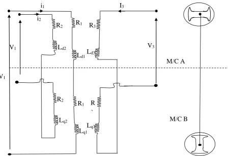
[image:2.595.88.537.77.384.2]VABC = rABC iABC + PλABC
Figure 2 Per phase schematic diagram of 3-phase transfer field motor with rotor (cage) windings.
i
2i
1R
2R
3L
d2R
1R
2R
1R
3L
d1L
d3L
q2L
q1L
q3V
1V
1V
3M/C A
9 doi: 10.32622/ijrat.82202007
(4) Vabc = rabc iabc + Pλabc
VdqrABC = rdqrABC idqrABC + PλdqrABC (5) Vdqrabc = rdqrabc idqrabc + Pλdqrabc
Where P , λ = flux
RABC = diag [(rA rB rC)] and rabc = diag [(ra rb rc)] The flux linkages are expressed as;
λABC = LGG iABC + LGH iabc λabc = LHG iABC + LHH iabc (6)
Where LGG, LGH, LHG and LHH are inductance matrices obtained from the inductance sub matrices of the two components machines as shown below.
Let L11 be the self inductance of the main winding and L22 be the self inductance of the auxiliary winding; then the mutual inductance between the main and the mutual inductance between the main and the auxiliary winding will be L12 or L21 as the case may be;
Now; L11 =
L12 = ±
L21 = ±
L12 = ±
So far the main and the auxiliary winding are identical, LGG = L11 (Machine A) + L11 (Machine B) = + The individual inductance expressions are as follows; LAA =La1 + La2 cos 2 θr, LAB = LBA = - ½ La1 ± La2 cos (2 θr – α)
LAC = LCA = - ½ La1 ± La2 cos (2 θr + α)
LBC = LCB = - ½ La1 ± La2 cos 2 θr, LBB = ½ La1 ± La2 cos (2 θr - α)
LCC = ½ La1 ± La2 cos (2 θr + α), Laa = ½ La1 ± La2 cos 2 θr Lab = Lba = ½ La1 ± Lb2 cos (2 θr - α), Lbc = Lcb = ½ Lb1 ± Lb2 cos 2 θr
Lbb = ½ Lb1 ± Lb2 cos (2 θr - α), Lcc = ½ La1 ± Lb2 cos (2 θr + α)
LAa = LaA = ½ Lb12 ± Lb12 cos 2 θr, LAb = LbA = ½ La12 cos α ± Lb12 cos (2 θr - α)
LAc = LcA = ½ La12 cos α ± Lb12 cos (2 θr + α), LBa = Lab = ½ La12 cos α ± Lb12 cos (2 θr - α)
LBb = LbB = ½ La12 cos α ± Lb12 cos (2 θr + α), LBc = LcB = ½ La12 cos α ± Lb12 cos 2 θr
LCa = LaC = ½ La12 cos α ± Lb12 cos (2 θr + α), LCb = LbC = ½ La12 cos α ± Lb12 cos 2 θr
LCc = LcC = ½ La12 cos α ± Lb12 cos (2 θr - α),
Where , α = , and; La11 = La22 = La12 = ½ (Lmd + Lmq) Lb11 = Lb22 = Lb12 = ½ (Lmd - Lmq)
However, the expressions for the individual inductances above, can further be used for the inductance matrix for the main windings for both machines A and B.
For machine A, the inductance matrix for the main winding is (Chem-mum O, 1997)
IV. ROTOR WINDING INDUCTANCE
The stages of transformation of the voltage equations are to first transform the a-b-c phase variables into q-d-o frame where the quantities are in stationary reference frame i.e. dr and qr. Since the rotor of this machine is salient pole, the axis of the rotor quantities are already in the q and d axis, so that the q-d-o transformation need only be applied to the stator quantities.
V. THE MACHINE MODEL IN ARBITRARY Q-D-O REFERENCE FRAME
In order to remove the rotor position dependence on the inductances seen in (8), the voltage equations in (4) need to be transferred to q-d-o reference frame. The technique is to transform all the stator variable to an arbitrary reference frame.
Here, all the stator variable will be transform to the rotor. In the voltage equations for the main and auxiliary windings of the transfer field machine of (4), there is no need to include the rotor equation here since our intension is to adopt rotor reference frame.
Hence, the voltage equations of the main winding of the machine will after the transformation yield;
VQ = ωλD + ρλQ + riQ
VD = ωλQ + ρλD + riD (9) VO = ρλO + riO
Doing like – wise for the auxiliary and cage (rotor) windings, we have,
Vq = (ω-2ωr) λd + ρλq + riq Vd = (ω-2ωr) λq+ ρλd+ rid
Vo = ρλo+ rio (10) = (ω -2ωr) + +
10 For machine B, the inductance matrix for the main winding is;
Hence LGG = +
Where LLs = leakage inductance, and Lo =
LGG = (7)
Now for mutual inductance, For machine A, the mutual inductance matrix is given as;
Likewise, for machine B, the mutual inductance matrix is given as;
But LGH = +
But
- 2Lms =
=
(8)
Where, α =
11 doi: 10.32622/ijrat.82202007
VI. TRANSFORMATION OF FLUX LINKAGES
The ABC and abc subscripts denote variables and parameters associated with the main and auxiliary windings respectively. Both rABC and rabc are diagonal matrices each with equal non zero elements. For a magnetically linear system, the flux linkages may be expressed as;
= Wb turns (11)
Where G = main winding, H = Auxiliary winding.
To transform the above equation in respect to the cage winding, we have as follows,
= (12)
The inductance matrix terms LGG, LGH, LHG and LHH are obtained from inductance sub-matrices L11, L12, L21 and L22 for machine A and B.
LGRA is the mutual inductance matrix between main winding of machine A and rotor winding of machine A.
LGRB is the mutual inductance matrix between main winding of machine B and rotor winding of machine B.
LHRA is the mutual inductance matrix between auxiliary winding of machine A and rotor winding of machine A LHRB is the mutual inductance matrix between auxiliary winding of machine B and rotor winding of machine B. LRARA is the inductance matrix of rotor winding of machine A.
LRARB is the mutual inductance matrix between the rotor winding of machine A and the rotor winding of machine B.
VII. STATOR WINDING INDUCTANCES
To reduce the mathematical complexities of equation 11, it is rewritten in q-d-o frame as;
=
(13)
Where KG = (14)
= (15)
KH = (16)
= (17)
Where = θ = Speed of rotation of the arbitrary reference frame
θr = Angular rotor position
Therefore the flux linkage of equation 11 is now expressed as;
λQ = (2LL + Lmq + Lmd) iQ – (Lmd – Lmq) (iq + )
= 2LL iQ + Lmq iQ + Lmd iQ - Lmd (iq + ) + Lmq (iq + ) = 2LL iQ + Lmq iQ + Lmd iQ + Lmd iQ - Lmd iQ - Lmd (iq + ) + Lmq (iq + )
= 2LL iQ + 2Lmd iQ + Lmq iQ- Lmd iQ - (iq + ) + Lmq (iq + ) = 2 (LL + Lmd) iQ + [iQ(Lmq - Lmd) +(iq + ) (Lmq - Lmd)] = 2 (LL + Lmd) iQ + (iQ + iq + ) (Lmq - Lmd)
λQ =2 (LL + Lmd) iQ + (Lmq - Lmd) (iQ + iq + ) (18) Similarly;
λD = (2LL + Lmq + Lmd) iD + (Lmd – Lmq) (id + ) =2 (LL + Lmq) iD + (Lmd - Lmq) (iD + id + ) (19) λO = 2LL iO (20)
Also, λq = (2LL + Lmq + Lmd) iq – (Lmd – Lmq) (iQ + ) = 2 (LL + Lmd) iq + (Lmq - Lmd) (iQ + iq + ) (21) λd = (2LL + Lmq + Lmd) id + (Lmd – Lmq) (iD + ) =2 (LL + Lmq) id + (Lmd - Lmq) (iD + id + ) (22) λo = 2LL io (23)
Also; = (LLqr + Lmq + Lmd) – (Lmd – Lmq) (iQ + iq) = (LLqr + 2Lmd) + (Lmq - Lmd) (iQ + iq + ) (24)
= (LLdr + Lmq + Lmd) – (Lmd – Lmq) (iD + id)
= (LLdr + 2Lmq) + (Lmd - Lmq) (id + id + ) (25)
NB: Upper case letters represent the main winding parameters, while the lower case letters and the primed lower case letters represent the auxiliary winding parameters and rotor winding parameters respectively
As before (18-20) represent the flux linkages of the main winding circuit while (21-23) represent the flux linkages of the auxiliary winding circuit. Also (24-25) represent the flux linkages of the caged (rotor) winding circuit, r in (9 and 10) is the sum of the resistances of the main, auxiliary and rotor windings in both machine halves. Equations 18-25 can be put into (9 and 10) to yield;
VQ = ωλD + ρ [2 (LL + Lmd) iQ + (Lmq - Lmd) (iQ + iq + )] + riQ (26)
Vq = (ω - 2ωr) λd + ρ [2 (LL + Lmd) iq + (Lmq - Lmd) (iQ + iq +
)] + riq (27)
= (ω - 2ωr) + ρ[(LLqr + 2Lmd) + (Lmq - Lmd) (iQ + iq + )+ (28)
VD = ωλQ + ρ [2 (LL + Lmq) iD + (Lmd - Lmq) (iD + id + )] + riD (29)
Vd = (ω - 2ωr) λq + ρ [2(LL + Lmq) id + (Lmd - Lmq) (iD + id + )] + rid (30)
= (ω - 2ωr) + [ρ (LLdr + 2Lmq) + (Lmd - Lmq) (id + id + )]+ (31)
Also for O-variables ; VO = λO +riO
= (2LL iO) + riO (32) VO = λo +rio
12 = + r
= (Lr ) + (34)
Equations 26 - 28 result the equivalent circuit shown in figure 3;
Also, equations 29 - 31 result the equivalent circuit shown in figure 4;
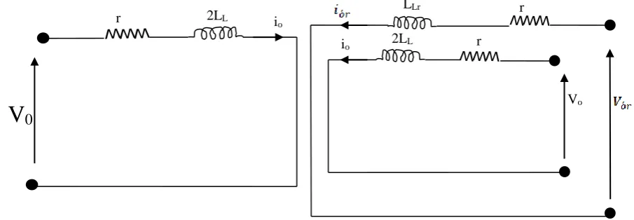
Similarly, equations 32 - 34 combine to yield the equivalent circuit shown in figure 5.
[image:6.595.40.538.127.301.2]Figure 5: Arbitrary reference frame equivalent circuit for a 3-phase symmetrical transfer field machine with cage (rotor) winding in the O-variable
Fig 3- Arbitrary reference frame equivalent circuit for a 3-phase symmetrical transfer field machine with cage (rotor) winding in the q-variable.
r
(iQ+iq+iqr) ωλD -2(LL + Lmd) iQ
iq
LLqr +2
Lmd
2(LL + Lmd)
(ω-2ωr)λd r
(Lmq - Lmd)
(ω-2ωr)λdr
VQ
+ - r
+ -
[image:6.595.44.552.344.513.2]Vq + -
Figure 4: Arbitrary reference frame equivalent circuit for a 3-phase symmetrical transfer field machine with cage (rotor) winding in the d-variable.
r
(iD+id+
) ωλQ -2(LL + Lmq) iD
id
LLdr +2 Lmq
2(LL + Lmq)
r
(Lmd - Lmq)
(ω-2ωr)λqr
VD
+ - r
+ -
V d + -
Vo r
V
0r 2LL io
LLr
2LL
[image:6.595.71.524.572.729.2]13 doi: 10.32622/ijrat.82202007
VIII. ROTOR TO STATOR WINDING INDUCTANCES
Obviously, both rotors of the machine halves are identical. Therefore, they possess equal and similar parameters. Let us consider the inductances between the rotor winding, and the stator windings of machine A. The winding placements are depicted in figure 6 below
From figure 6,
LGRA=LRAG=
(35)
LHRB = LRBH =
NB LGRA = LHRB on the account if the identity of the two machine halves.
Also
Laq = LAq = Lmq cos θr, Lad = LAd = Lmd sin θr
Lbq = LBq = Lmq cos (θr- ), Lbd = LBd = Lmd sin (θr- )
Lcq = LCq = Lmq cos (θr- ), Lcd = LCd = Lmd sin (θr- ) (36)
IX. ROTOR TO ROTOR WINDING INDUCTANCES
On the account of identity of the two machine halves;
LRARA = LRBRB = (37)
X. THE TORQUE EQUATION OF THE 3-PHASE TRANSFER
FIELD MACHINE WITH CAGE (ROTOR)WINDING
The torque equation of the configured machine is obtained by integrating the rotor winding parameters into the derived torque equation of the conventional 3-phase transfer field machine with no rotor winding.
The expression for the torque equation of the cage winding transfer field machine is given as;
Te =
- (38)
Where,
iQs is the q-axis stator current in the main winding of transfer field machine
iqs is the q-axis stator current in the auxiliary winding of transfer field machine
iDs is the d-axis stator current in the main winding of transfer field machine
ids is the d-axis stator current in the auxiliary winding of transfer field machine i r is the d axis rotor current in the (cage) rotor of transfer field machine.
14 A
B C
Main winding
a
b c
Auxiliary Winding
A
B C
Main winding
a
b c
Auxiliary Winding
Rotor (Cage)
Winding Rotor (Cage)
Winding q
d
q
M/C A M/C B
15 doi: 10.32622/ijrat.82202007
[image:9.612.63.343.110.241.2]XI. CIRCUIT PARAMETERS FOR THE DYNAMIC STATE SIMULATION OF THE MACHINE
Table 1
S/No Parameter Value
1 Lmd 133.3mH
2 Lmq 25.6mH
3 LLs = Lia = Ler 0.6mH
4 rm = ra = rr = r 3.0Ω
5 J 1.98x10⁻³kgm3
6 V 220V
7 F 50HZ
8 P 2
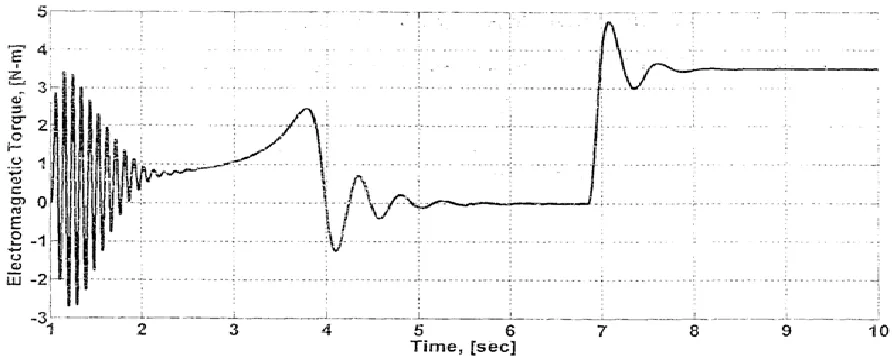
[image:9.612.86.498.284.461.2]Matlab plots for the machine output characteristics using (1) through (38), the plots of the machine’s output characteristics are shown in figure 7 and 8.
Figure 7: Rotor speed run up plot for the configured machine
[image:9.612.70.516.495.676.2]16
Author-1 Photo
Author-2 Photo
Author-3 Photo
XII. RESULT AND ANALYSIS OF THE MACHINE
For the dynamic operation of the machine, the rotor speed run-up plot against time for the configured (cage) machine is shown in figure 7. There was a little transient at different stages while rotor speed builds up before an application of load at 7 seconds. After another little transient, the rotor speed now settles to a steady-state at about 1410N-m. Also the graph of electromagnetic torque against time for the caged machine with oscillations noticed at different stages is shown in figure 8. It is observed that on no-load, value for electromagnetic torque is zero. On application of load torque at 6.9 seconds to the machine, it oscillates and settled to a steady-state of 3.4N.
XIII. CONCLUSION
From the analysis of the improved transfer field machine, the inclusion of rotor winding into the conventional machine provides better output performance characteristics, necessary for its wider applications in engineering industries (Fitzgerald A.E, Charles K. Jr, Stephen D.U. 2003), (Gupta J.B 2006), (Menta, V.K. Rotit Menta (2000).
A
CKNOWLEDGEMENTThe authors acknowledge the support of the Department of Electrical Engineering, Nnamdi Azikiwe University, Awka, for using their apparatus / prototype machines for experiments / analysis.
REFERENCES
[1] Agu, L. A. (1984). Output enhancement in the transfer-field machine using rotor circuit induced currents. Nigeria Journal of Technology Vol. 8, No. 1. Pp. 7 – 11.
[2] Agu, L. A. & Anih, L. U. (2002). Couple Poly phase reluctance machine without rotating windings. A technical Transactions of Nigeria society of Engineers. Pp. 37, 46 – 53.
[3] Agu, L. A. (1978). The transfer field machine, Electric Machine and Electro Mechanics. pp 403-418.
[4] Chee-mun O. (1997). Dynamic Simulation of Electric Machinery using Matlab/simulink. Prentice Hall PTR, New Jersey.
[5] Fitzgerald, A. E; Charles, K. Jr. & Stephen, D. U. (2003). Electric Machinery, Tata McGraw-Hill
[6] Gupta, J. B. (2006). Theory and performance of Electrical machine. S.K Katania and Sons 4424/6 Guru Namak Market, Naisarak Delhi-110006, pp. 578-579.
[7] Menta, V.K. & Rotit M. (2000). “Principles of Electrical Machines” published by S. Chand and Company Ltd. Rann Nagar, New Delhi – 110055 pp 386
AUTHORSPROFILE
Obute Kingsley Chibueze obtained his First Degree (B.Eng) and Second Degree (M.Eng) all in Electrical Engineering from the University of Benin, Benin City and Nnamdi Azikiwe University Awka respectively. He is att he verge of bagging his Ph.D (Electrical Machine Option) in Electrical Engineering. He is a registered Engineer with COREN. He is currently a lecturer in the department of Electrical Engineering, Nnamdi Azikiwe University, Awka, Anambra State, Nigeria.
Prof. Olufolahan Oduyemi is currently an Associate Professor of Facilities and Construction Project Management at the Southeast Missouri State University, Cape Girardeau, Missouri, USA. He had his Bachelors degree in Estate Ma nagement from the Federal University of Technology, Akure, Ondo State Nigeria in 2008, his Masters degree in Property Management and Investment from Edinburgh Napier University, Scotland, UK in 2011, a PhD in Facilities Management from University of Derby, UK in 2015 and a Masters in Business Administration (MBA) from Southeast Missouri State University, Cape Girardeau, Missouri, USA in 2019.