Available online at www.ijrat.org
1
Fabrication, Material and Design Modification based
Analysis of Connecting Rod Using FEA
Aditya Chaudhary
1, Dr. Prashanta Kr Mahato
21.Student(Final year), B.Tech, Department Of Mechanical Engineering,IIT( ISM)Dhanbad 2.Assistant Professor, Department Of Mechanical Engineering,IIT(ISM)Dhanbad
Email: [email protected],[email protected]
Abstract- Connecting rod is a critical element in an automotive power transmission system, being the kinematic link between the piston and the crankshaft. It is used to convert the reciprocating motion of the piston to the rotary motion of the crankshaft. In the present study,the stress and deformation analysis of the connecting rod has been carried out,and viable changes in three domains, namely the manufacturing processes, material and design of the connecting rod,have been proposed. Under the head of manufacturing processes, different processes including forging and sintering have been discussed. Effect of shot peening on fatigue strength and heat treatment on the overall performance of the connecting rod have been taken into account. Newer and more efficient materials, namely C-70 steel, Micro-alloyed steels and aluminium based composites with particle and fiber reinforcements have been tested. Lastly, the design of the connecting rod has been modified to get the best combination of overall stress, stress concentration and deformation. In this process, areas of high stress concentrations are identified and attempts have been made to relieve stresses in these sections. Modifications in each of the above mentioned stages have led to stress and weight reduction and increase in the stiffness,thus enhancing the overall performance of the connecting rod.
Static and fatigue analysis has been carried out in ANSYS 15.0 Workbench. Output parameters including Von Mises stress, total deformation, factor of safety, fatigue life and fatigue factor of safety have been used for comparative study of the modified models and their existing counterparts.
Index Terms- Connecting rod, FEA, Forging, Sintering, Peening, MMCs, Fatigue
1. INTRODUCTION
Connecting rod is one of the most critical element of the engine assembly acting as a link between the piston and the crankshaft. One end of the connecting rod, known as the small end is connected to the piston by means of a gudgeon pin, while the big end is connected to the crankshaft by means of a crank pin. Connecting rod is subjected to tensile and compressive loading which are cyclic in nature. Hence, the connecting rod is generally subjected to fatigue failure. However, a static structural analysis may be used for comparison purposes. In this paper, both static and fatigue analysis has been carried out as per requirement. Connecting rods are generally manufactured through steel forging, which is both efficient and cost-effective. However due to high expenditure of subsequent machining and crackability problems, powder metallurgy is slowly gaining wide acceptance. Casting may also be used as the manufacturing process, but the formation of blowholes during casting greatly reduce the fatigue strength of the final product. The materials used for connecting rod include steel(strength and low cost), aluminium(lightness and ability to absorb impact
loads) and titanium(used in high performance engines where the high costs are justified).The cross-section of the connecting rod is generally of I section or H-section.
There is a scope of modification at various stages in the production of the connecting rod. Effective implementation of these modifications serve the purpose of effective reduction in weight, increase in durability, reduction in fuel consumption and less emission.Since connecting rods are manufactured in the industry on a large scale,a small reduction in weight has a massive impact on the reduction in overall costs.
2. LITERATURE REVIEW
2 rod made of AlFASiC composites and concluded
that the composite connecting rod has higher strength and stiffness and is comparatively lighter than it’s counterpart made of Al-360.Mr.Vivek T.Fegade [3] et al, in his paper concluded that insertion of titanium strips on both sides of shank in steel connecting rod increases the strength and stiffness.Mithilesh K Lade [5] et al,carried out static load analysis of a carbon fiber connecting rod.An increase in strength and stiffness and reduction in weight (about 50%) was observed for carbon fiber as compared to the Aluminium alloy 7075 connecting rod.Hitesh Kumar [6] et al,in his paper tested AISI 1045 Carbon Steel and AISI 4340 Alloy steel as the constituent material of the connecting rod and observed that value of Von-Mises stress is less for AISI 4340 steel than AISI 1045 carbon steel.Shenoy P.S. and Fatemi A [7] ,in their research,ventured to optimize the connecting rod for weight and cost reduction towards the end of large scale savings.Adila Afzal [8],in her master’s thesis,investigated the fatigue behaviour of forged steel and powder metal connecting rods and elucidated the pros and cons of each process based on
strength,stiffness,crackability,durability,manufactur ing costs amongst other parameters.TArun Kumar Reddy [9] et al,performed the optimization of connecting rod for reduced weight and demonstrated that the weight of connecting rod for forged steel is considerably less than carbon steel.Vikram A Shedge [10] et al,modified the design of connecting rod by means of topological optimization on the basis of static and fatigue analysis.ShahrukhShamim [11],employed E-glass epoxy resin and Aluminium-Carbon nano-tube composites as material for connecting rod.Parameters namely Von-Mises stress,totaldeformation,elasticstrain,etc were tested for both the materials.
3. OBJECTIVE
The main objective of this paper is to modify and optimize the connecting rod in terms of manufacturing process,constituent material and design for enhancing performance and reducing weight.To achieve the final objective,the scope of the paper is as follows:-
(1) To develop a geometric model of the connecting rod based on standard dimensions in modelling software CATIA V5R20.
(2) To substantiate the advantages of crackable C-70 steel and micro-alloyed steel over conventional manufacturing processes.
(3) To demonstrate the effect of shot peening on fatigue strength and subsequent heat treatment on overall performance and weight of connecting rod (4) To analyse metal matrix composites composites with particle and fiber reinforcements in the light of lower weight and increased stiffness.
(5) To identify sections of high stress concentration and make provisions in design to relieve these stresses.
Effects of each of the above modifications have been shown through a comparative static and fatigue structural analysis carried out in the FEM software ANSYS. The output parameters include Von Mises stress, total deformation, factor of safety, fatigue life and fatigue factor of safety.
4. DESIGN OF CONNECTING ROD
The design of the connecting rod has been done on the basis of dimensions calculated analytically from the forces acting in a standard single cylinder petrol engine. The forces acting on the connecting rod include:-
(1) Force due to combustion pressure on piston (2) Inertia of the reciprocating parts
(3) Friction of the piston rings and the piston (4) Friction at the piston pin bearing and crank pin bearing
4. INPUT PARAMETERS FOR DESIGN:
Table 1. Input parameters
Diameter of piston 57 mm
Length of connecting rod 200 mm
Mass of the reciprocating parts 1.6 Kg
Stroke 58.6 mm
Speed 8500 rpm
Comression ratio 9.35
Combustion pressure 16 MPa
The output parameters required for designing the model of connecting rod are calculated from the following formula:-
Force acting on piston due to combustion pressure (Fg) = πd
2
/4×(Combustion pressure) (1)
Inertia load on the piston (Fi) = mω2r (1+1/n)
(n=l/r) (2) Buckling load (F) = Fg-Fi(3)
Rankine's formula :F = (C×A)/[1+a(L/Kxx)2] ,
where C = compressive yield stress (4)
A= Area of cross section=11(t2) (5)
Available online at
a= 0.002(7)
[image:3.595.317.528.99.198.2]5. OUTPUT PARAMETERS
Table 2. Output parameters Thickness of the
connecting rod(t) Width of the section Height of the section Height at the crank end Height at the piston end Inner diameter of the piston end
Outer diameter of the piston end
Inner diameter of the crank end
Outer diameter of the crank end
6. MODELLING OF CONNECTING ROD
[image:3.595.65.290.161.328.2]The model of the connecting rod was designed in the modelling software CATIA V5R20 in accordance with the dimensions obtained in the preceding discussion. The 3D model of the connecting rod is as shown in Fig.1.
Fig.1. Model of connecting rod
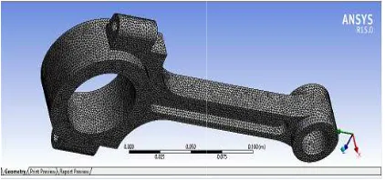
7. MESHING OF CONNECTING ROD
A finite element tetrahederal mesh was generated with a global element size of 2 mm.
model of the connecting rod is as shown in Fig.2.
Available online at www.ijrat.org
Table 2. Output parameters 4.5 mm
18 mm 22.5 mm
34 mm 32 mm 24 mm 38 mm 58 mm 78 mm
6. MODELLING OF CONNECTING ROD
The model of the connecting rod was designed in the modelling software CATIA V5R20 in dimensions obtained in the preceding discussion. The 3D model of the
.
1. Model of connecting rod
7. MESHING OF CONNECTING ROD
A finite element tetrahederal mesh was generated with a global element size of 2 mm. The meshed model of the connecting rod is as shown in Fig.2.
Fig. 2. Meshed model of connecting rod
8. LOADS AND CONSTRAINTS
(1) All degrees of freedom were constrained at the crank end.
(2) For static structural analysis, an axial compressive load of 30188 N was applied at the piston end .This force was calculated as the resultant of force due to combustion pressure(corresponding to a combustion pressure of 16MPa) and force due to inertia of the reciprocating masses.
(3) For fatigue structural anal
was subjected to a fully reversed load of 30188 N with crank end fixed.
[image:3.595.71.282.434.590.2]The application of fixed support on crank end and force on piston end is shown in Fig.3 and Fig.4 respectively.
[image:3.595.316.529.443.559.2]Fig. 3. Fixed support on crank end
Fig. 4. Force on piston end
3 Fig. 2. Meshed model of connecting rod
8. LOADS AND CONSTRAINTS
(1) All degrees of freedom were constrained at the (2) For static structural analysis, an axial 30188 N was applied at the piston end .This force was calculated as the resultant of force due to combustion pressure(corresponding to a combustion pressure of 16MPa) and force due to inertia of the reciprocating (3) For fatigue structural analysis, the piston end was subjected to a fully reversed load of 30188 N
The application of fixed support on crank end and force on piston end is shown in Fig.3 and Fig.4
Fig. 3. Fixed support on crank end
[image:3.595.316.528.573.690.2]9. MANUFACTURING PROCESS
9.1. Primary manufacturing process
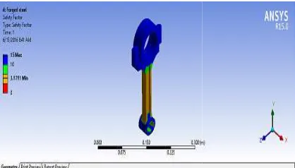
[image:4.595.314.535.225.406.2]Forging and sintering are the conventional processes for manufacture of the connecting rod. (1)Forging is a plastic deformation process in which the final part is made by the application of pressure to a metal billet at room temperature(cold forging) or elevated temperatures(hot forging).The connecting rod made of forged steel has high stiffness, good toughness, resistance to impact and fatigue. The factor of safety and total deformation may be calculated using FEA as shown in Fig.5 and Fig.6.
[image:4.595.72.281.300.419.2]Fig. 5. Safety factor (Forged con rod)
Fig. 6. Total deformation (Forged con rod) Problem Specification: The cap of the connecting rod must be separated from the rod to incorporate the rod in the piston assembly. This may be accomplished by means of fracture splitting. The major problem is that extensive machining is required after fracture splitting leading to production costs.
(2) Powder metallurgy is the process in which the metal powder is compacted under ambient temperature and very high pressure to achieve the final shape. Advantages include near net shape manufacturing and easy crackability (that a for easy separation of the cap from the rod). 9. MANUFACTURING PROCESS
Primary manufacturing process
Forging and sintering are the conventional processes for manufacture of the connecting rod.
[image:4.595.312.534.304.485.2]is a plastic deformation process in which the final part is made by the application of pressure to a metal billet at room temperature(cold forging) or elevated temperatures(hot forging).The connecting rod made of forged steel has high hness, resistance to impact and fatigue. The factor of safety and total deformation may be calculated using FEA as shown in Fig.5 and
Fig. 5. Safety factor (Forged con rod)
6. Total deformation (Forged con rod) e cap of the connecting rod must be separated from the rod to incorporate the rod in the piston assembly. This may be accomplished by means of fracture splitting. The major problem is that extensive machining is required after fracture splitting leading to higher
is the process in which the metal powder is compacted under ambient temperature and very high pressure to achieve the final shape. Advantages include near net shape manufacturing and easy crackability (that accounts for easy separation of the cap from the rod).
Problem Specification: The cost of manufacturing is very high due to a large number of secondary processes involved. Moreover, the strength and stiffness of the rod is less than that of forged rod, as may be validated from the FEA diagrams below (Fig.7 and Fig.8).
Fig. 7. Total deformation (Sintered con rod)
Fig. 8. Safety factor (Sintered con rod)
The two problems associated with the conventional manufacturing processes are addressed by the introduction of two new materials, namely :
a) C-70(Crackable Steel)
C-70 crackable steel is a form of high carbon micro-alloyed steel,main alloying elementsbeingsilicon,phosporous,sulphur,managan ese and vanadium shots. These steels provide for easy fracture splitting, besides incurring low manufacturing costs and high strength and stiffness compared to steel forged and powder forged connecting rod.
b) A-656(Micro-alloyed Steel)
A-656 steel is a series of high strength,lowalloy,hot-rolled steels with an excell combination of strength and formability and is suitable for applications where high strength to weight ratios are required.A small quantity of vanadium is added to obtain a refined grain size.Higher weldability and formability of these 4 The cost of manufacturing is very high due to a large number of secondary processes involved. Moreover, the strength and stiffness of the rod is less than that of forged rod, as ay be validated from the FEA diagrams below
Fig. 7. Total deformation (Sintered con rod)
Fig. 8. Safety factor (Sintered con rod)
The two problems associated with the conventional manufacturing processes are addressed by the introduction of two new materials, namely :-
70(Crackable Steel)
70 crackable steel is a form of high carbon alloyed steel,main alloying silicon,phosporous,sulphur,managan ese and vanadium shots. These steels provide for
e splitting, besides incurring low manufacturing costs and high strength and stiffness compared to steel forged and powder forged
alloyed Steel)
[image:4.595.71.282.449.581.2]Available online at
[image:5.595.315.528.109.228.2]steels is a veritable factor in cutting down the machining costs.
Table 3. Material properties
Material properties
C-70 Steel
Density(Kg/m3) 7850 Modulus of
elasticity(GPa)
212
Poisson’s ratio 0.33 Yield
strength(MPa)
574 Ultimate tensile
strength(MPa)
966
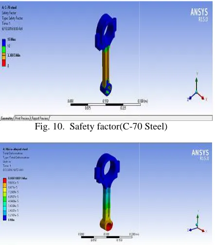
[image:5.595.67.287.166.286.2]The FEA diagrams of total deformation and safety factor for C-70 Steel (Fig.9 and Fig.10) and Micro alloyed steel (Fig.11 and Fig.12) are shown below:
Fig. 9. Total
deformation(C-Fig. 10. Safety factor(C-70 Steel)
Fig. 11. Total deformation (Micro
Available online at www.ijrat.org
table factor in cutting down the
Table 3. Material properties
Micro-alloyed steel
7850 206
0.29 550 655
The FEA diagrams of total deformation and safety 70 Steel (Fig.9 and Fig.10) and Micro-alloyed steel (Fig.11 and Fig.12) are shown below:
-70 Steel)
70 Steel)
Fig. 11. Total deformation (Micro-alloyed steel)
Fig. 12. Safety factor (Micro
Table 4:A comparative study of the strength and stiffness of the connecting rod manufactured by the above mentioned processes was made
form:
Materials Strength (N)
Stiffness(N/
Forged steel
95729. 166
134.686 Sintered
steel
43512 139.768 C-70 steel 99907.
186
141.882 Micro
alloyed steel
95689. 922
137.804
In the conventional manufacturing processes,forged connecting rod has higher strength and lower weight than sintered connecting rod but incur higher machining costs due to crackabilityproblems.Advanced materials,C 70(Crackable) steel and Micro
addressing the problem of crackability,exhibit a desirable edge over conventional processes in terms of strength,stiffness and weight.
9.2 Shot peening and Subsequent heat treatment
9.2.1Shot peening
Shot peening is the process by which the
the structural material is impacted by small particles, called shots. As a result of this process, residual stresses are produced on the surface. These residual stresses arrest the propagation of micro cracks and consequently enhance the fatigue strength of the material.
The increase in fatigue strength of the connecting rod has been demonstrated by the following analysis. Steel shots have been used for peening the surface of the connecting rod.
5 Safety factor (Micro-alloyed steel) A comparative study of the strength and stiffness of the connecting rod manufactured by the above mentioned processes was made in the tabular
Stiffness(N/ mm)
Optimized model weight(kg) 134.686 1.4353 139.768 1.4457 141.882 1.4084 137.804 1.4084
In the conventional manufacturing processes,forged connecting rod has higher strength and lower weight than sintered connecting rod but incur higher machining costs due to crackabilityproblems.Advanced materials,C-70(Crackable) steel and Micro-alloyed steel,besides addressing the problem of crackability,exhibit a desirable edge over conventional processes in terms of strength,stiffness and weight.
Shot peening and Subsequent heat treatment
Shot peening is the process by which the surface of the structural material is impacted by small particles, called shots. As a result of this process, residual stresses are produced on the surface. These residual stresses arrest the propagation of micro-cracks and consequently enhance the fatigue
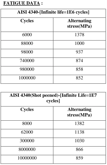
[image:5.595.73.290.344.472.2] [image:5.595.72.293.503.755.2]FATIGUE DATA :
AISI 4340(Shot peened)-[Infinite Life=1E7 cycles]
Cycles Alternating
stress(MPa)
8000 62000 300000 8000000 10000000
The fatigue life and fatigue factor of safety for steel(before shot peening) i.e.Fig.13 and Fig.14 and steel(after shot peening) i.e.Fig.15 and Fig.16 have been shown below.
[image:6.595.313.538.97.214.2]Before shot peening:
Fig.13. Fatigue life AISI 4340-[Infinite life=1E6
Cycles Alternating
stress(MPa)
6000 88000 98000 740000 980000 1000000
[Infinite Life=1E7
Alternating stress(MPa)
1382 1138 1030 866 859
[image:6.595.65.288.115.459.2]The fatigue life and fatigue factor of safety for (before shot peening) i.e.Fig.13 and Fig.14, l(after shot peening) i.e.Fig.15 and Fig.16
Fig.13. Fatigue life
[image:6.595.312.536.260.534.2]Fig.14. Fatigue safety f After shot peening:
Fig.15. Fatigue life
Fig.16. Fatigue safety factor
Results :
Shot peening has a desirable effect of enhancing the fatigue life and fatigue factor of safety of connecting rod.A7.15% increase in fatigue life as a result of shot peening may be observed from the table.
Table 5. Effect of shot peening Materials Fatigue
life(cycles)
Steel(without shot peening)
9.869e5
Steel(Shot peened)
8.043e6 [Infinite life=1E6 cycles]
Alternating stress(MPa)
1378 1000 937 874 858 852
6 Fig.14. Fatigue safety factor
tigue life
Fig.16. Fatigue safety factor
Shot peening has a desirable effect of enhancing the fatigue life and fatigue factor of safety of increase in fatigue life as a result of shot peening may be observed from the
Table 5. Effect of shot peening Fatigue
ife(cycles)
Factor of safety
9.869e5 5.007
[image:6.595.72.292.552.678.2]Available online at
9.2.2 Heat treatment
Shot peening results in residual compressive stresses on the surface of the connecting rod. These stresses are relieved by heating the material to a temperature below the critical temperature and then cooling uniformly. The aforesaid heat re technique serves to enhance the strength and stiffness of the connecting rod.
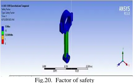
The FEA diagrams before and after the process have been shown below,output parameters involving total deformation(Fig.17 and Fig.19) and factor of safety(Fig.18 and Fig.20).
[image:7.595.315.533.110.244.2]Before heat treatment :
Fig.17. Total deformation
[image:7.595.71.289.310.501.2]Fig.18. Factor of safety After heat treatment :
Fig.19. Total deformation
Available online at www.ijrat.org
Shot peening results in residual compressive stresses on the surface of the connecting rod. These stresses are relieved by heating the material to a temperature below the critical temperature and then cooling uniformly. The aforesaid heat relieving technique serves to enhance the strength and
The FEA diagrams before and after the process have been shown below,output parameters volving total deformation(Fig.17 and Fig.19) and
Fig.17. Total deformation
[image:7.595.72.289.624.746.2]Fig.18. Factor of safety
Fig.19. Total deformation
Fig.20. Factor of safety Results :
An increase in strength and stiffness has been observed as a result of the elimination of residual stresses from the surface of connecting rod by heat treatment process.
Table 6. Effect of heat treatment Heat
treatment
Strength(N)
Before 81.2845 After 152.473
10. MATERIALS
Structural steel and aluminium are the conventional materials used for the manufacture of the connecting rod. In recent times, metal matrix composites(MMCs) have opened up new possibilities for achieving enhanced mechanical properties at a lower cost. In this paper, the materials tested constitute the following:
(1) Al-6061 -Aluminum alloy 6061 is a precipitation hardened aluminiumalloy,containing magnesium and silicon as it’s major alloying elements.
(2) Al-15% Al2O3- MMC with aluminium as the
metal matrix with alumina reinforcements in form of continuous fibres.
(3) Al-10%SiC - Aluminium metal matrix with silicon carbide reinforcements in the form of whiskers.
7 Fig.20. Factor of safety
An increase in strength and stiffness has been elimination of residual stresses from the surface of connecting rod by heat
Table 6. Effect of heat treatment
Strength(N) Stiffness(N/mm)
128.495 133.859
and aluminium are the conventional materials used for the manufacture of the connecting rod. In recent times, metal matrix composites(MMCs) have opened up new possibilities for achieving enhanced mechanical properties at a lower cost. In this paper, the
terials tested constitute the following:-
Aluminum alloy 6061 is a precipitation hardened aluminiumalloy,containing magnesium and silicon as it’s major alloying
MMC with aluminium as the reinforcements in form
Table 7. Material properties
Materials Al-6061 Al-15%Al2O
Density(k g/m3)
2700 2890
Young's Modulus( Gpa)
68.9 119.63
Poisson's ratio
0.33 0.33
Tensile strength( MPa)
276 173
Behaviour Isotropic Isotropic
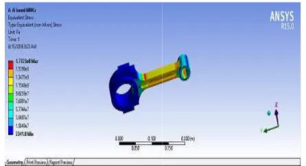
The Von-Mises stress and total deformation for each of the test materials discussed in the previous section,may be validated from the FEA diagrams below.
Al-6061:
Fig.21. Von-Mises stress
[image:8.595.67.287.140.396.2]Fig.22. Total deformation Table 7. Material properties
O3
Al-10%SiC
2730
93.7
0.33
233
Isotropic Isotropic
Mises stress and total deformation for each of the test materials discussed in the previous section,may be validated from the FEA diagrams
Mises stress
Fig.22. Total deformation
[image:8.595.312.535.154.275.2]Al-15%Al2O3:
Fig.23. Von-Mises stress
Fig.24. Total deformation
[image:8.595.234.529.466.766.2]Al-10%SiC:
Fig.25. Von-Mises stress
Fig.26. Total deformation
8 Mises stress
Fig.24. Total deformation
Mises stress
Available online at
Results:
The replacement of conventional Al
[image:9.595.314.533.97.211.2]aluminium based composites has led to a patent increment in the stiffness and reduction in weight of the connecting rod.Moreover,introduction of MMCs as the constituent material for the connecting rod will open up new and infinite number of possibilities for the manufacture of high performance connecting rods at lower costs.
Table 8.Stiffess and weight for different materials Materials Stiffness
(N/mm)
Aluminum alloy-6061
15.885
Al-15% Al2O3 21.964
Al-10% SiC 21.845
11. DESIGN MODIFICATION
[image:9.595.66.287.231.334.2]The forces in the connecting rod produce very high stresses in the shank region at the two ends. The non-uniform distribution of the stresses in this region also alleviate the chances of failure of the shank of the connecting rod. This condition may be demonstrated by the following stress analysis diagram of structural steel connecting rod(Fig.27
Fig.27. Von-misesstress(structural steel) The stresses may be released by cutting small holes at appropriate locations. The holes are coated with titanium to provide extra strength as these holes become the centers of stress concentration. The diagram below shows the condition of stresses in the modified design:
Available online at www.ijrat.org
The replacement of conventional Al-6061 by aluminium based composites has led to a patent increment in the stiffness and reduction in weight of the connecting rod.Moreover,introduction of MMCs as the constituent material for the
cting rod will open up new and infinite number of possibilities for the manufacture of high performance connecting rods at lower costs.
Table 8.Stiffess and weight for different materials Weight(kg)
0.52619
0.56322 0.53204
The forces in the connecting rod produce very high stresses in the shank region at the two ends. The uniform distribution of the stresses in this alleviate the chances of failure of the shank of the connecting rod. This condition may be demonstrated by the following stress analysis
ural steel connecting rod(Fig.27)
misesstress(structural steel) eased by cutting small holes at appropriate locations. The holes are coated with titanium to provide extra strength as these holes become the centers of stress concentration. The diagram below shows the condition of stresses in
Fig.28. Modified design of connecting rod
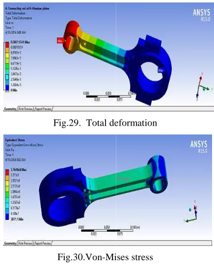
[image:9.595.312.530.256.528.2]FEA diagrams of the modified model
Fig.29. Total deformation
Fig.30.Von-Mises stress The FEAdiagram shown in Fig.30
the stresses in the shank region for the modified model is less than that for the original model. The titanium coating provided on the holes ensure that crack initiation does not occur at the holes (due to stress concentration).The result
tabular form as shown below:
Table 9. Effect of design modification
Design M
Conventional model Modified model
The stresses in the shank region for the modified model is less than that of the original values.There has been a 3.4 % reduction in the magnitude of stresses as may be calculated from the values listed in the table.
9 Fig.28. Modified design of connecting rod
FEA diagrams of the modified model:
Fig.29. Total deformation
Mises stress
diagram shown in Fig.30 demonstrate that the stresses in the shank region for the modified model is less than that for the original model. The titanium coating provided on the holes ensure that crack initiation does not occur at the holes (due to stress concentration).The results may be shown in a tabular form as shown below:
Table 9. Effect of design modification Maximum stress in
shank region(Pa) 1.7344E08 1.6755E08
[image:9.595.72.287.455.579.2]10 12. CONCLUSION
In this paper, modifications in the connecting rod in three areas namely, manufacturing process, material and design have been proposed. The results and validity of the discussed changes may be summarised as follows:
(1) Besides addressing the problem of crackability of connecting rod, advanced materials namely, C-70 (Crackable) steel and Micro-alloyed steel exhibit better combination of strength and stiffness than steel manufactured by forging and sintering. Weight reduction in the latter two cases compared to forged and sintered steel is also quite evident. (2) Shot peening serves to increase the fatigue life and improves the fatigue strength of the model. The residual stresses produced on the surface as a result of shot peening may be relieved by subsequent heat treatment.
(3) The connecting rods made of metal matrix composites (namely, Al-15%Al2O3 and
Al-10%SiC) have lower weight and higher stiffness than that manufactured by the conventional material (i.e. Al-6061).
(4) The stresses in the shank section may be reduced by machining small holes at appropriate locations in the connecting rod. There is 3.395% reduction in Maximum Von-Mises stress in the modified model.
(5) The stress distribution is more uniform in case of the modified model.
13. ACKNOWLEDGEMENT
On successful completion of my project, I would sincerely like to thank my mentor Dr.Prashanta Kumar Mahato who gave me the permission to carry out this research under his guidance. I express my solidarity towards him for his precious guidance right from the beginning of the project.
REFERENCES
[1] KadiamBhargav; V Siva Kumar (2014):Comparative Study of the Connecting Rod Manufactured Using Forging and Sintering International Journal of Scientific & Engineering Research, Volume 5, Issue 5,ISSN: 2229-5518,pp. 1292-1294.
[2] Kuldeep, B.;Arun, L.R.; Mohammed Faheem ,(2013):Analysis And Optimization Of
Connecting Rod Using AlFASiC Composites, International Journal of Innovative Research in Science, Engineering and Technology Vol. 2, Issue 6, ISSN: 2319-8753, pp. 2480-2487.
[3] Mr. Vivek T. Fegade; Dr. Kiran S. Bhole (2015):Finite Element Analysis and Material Optimization for Equivalent Strength of Composite Connecting Rod,SSRG International Journal of Mechanical Engineering (SSRG-IJME), Volume 2, Issue 2, pp. 34-40.
[4] V.B.BHANDARI; Design Of Machine Elements, 3rd Edition, McGraw Hill Publications.
[5] Mithilesh K Lade; Ritesh P Harode; DeepaliBankar Lade (2015):Static Load Analysis of Carbon Fiber Connecting Rod, International Journal of Research in Advent Technology, Vol.3, No.9E-ISSN: 2321-9637, pp. 20-30.
[6] Hitesh Kumar; Vijay Kumar Sharma (2015):Stress Analysis and Optimization of I. C. Engine Connecting Rod by Finite Element Analysis”, International Journal of Engineering Research & Technology (IJERT), Vol. 4, Issue 04, ISSN: 2278-0181, pp. 590-595.
[7] Shenoy, P. S.;Fatemi, A. (2005):Connecting rod optimization for weight and cost reduction, SAETechnical Paper 01-0987.
[8] Adila Afzal (2004): Fatigue Behavior and Life Predictions of Forged Steel and PowderMetal Connecting Rods, Master’s thesis, The University of Toledo.
[9] T Arun Kumar Reddy; M Sachidanandham (2015):Comparison of Two Different Materials for Connecting Rod using ANSYS, IJIRST – International Journal for Innovative Research in Science & Technology, Volume 1,Issue 11, ISSN: 2349-6010, pp. 306-313.
[10] Mr. Vikram A. Shedge; Prof. K. H. Munde(2015):Optimization of Connecting Rod on the basis of Static & Fatigue Analysis, IPASJ International Journal of Mechanical Engineering (IIJME), Volume 3, Issue 5,ISSN: 2321-6441, pp. 7-13.