R E S E A R C H
Open Access
Unified approach to cross-layer scheduling and
resource allocation in OFDMA wireless networks
Guillem Femenias
*, Borja Dañobeitia and Felip Riera-Palou
Abstract
Orthogonal frequency division multiple access (OFDMA) has been selected as the core physical layer access scheme for state-of-the-art and next-generation wireless communications standards. In these systems, scheduling and resource allocation algorithms, jointly assigning transmission data rates, bandwidth and power, become crucial to optimize the resource utilization while providing support to multimedia applications with heterogeneous quality of service (QoS) requirements. In this article, a unified framework for channeland queue-aware QoS-guaranteed cross-layer scheduling and resource allocation algorithms for heterogeneous multiservice OFDMA wireless networks is presented. The framework encompasses different types of traffic, uniform and continuous power allocation, discrete and continuous rate allocation, and protocols with different amounts of channel- and queue-awareness. System parameters and QoS requirements are projected into utility functions and the optimization problem is then formulated as a constrained utility maximization problem. Optimal solutions for this problem are obtained for the uniform power allocation schemes, and novel quasioptimal algorithms are proposed for the adaptive power allocation strategies. Remarkably, these techniques exhibit complexities that are linear in the number of resource units and users. Simulation results demonstrate the validity and merits of the proposed cross-layer unified approach.
1 Introduction
Due to its high spectral efficiency, inherent robustness against frequency-selective fading and flexibility in resource allocation, orthogonal frequency division multi-ple access (OFDMA), combined with multimulti-ple-input multiple-output (MIMO) strategies, has been chosen as the multiple access technique for state-of-the-art and next-generation wireless communications standards such as IEEE 802.16e/m-based WiMAX systems [1] and Third Generation Partnership Project (3GPP) technolo-gies based on the long-term evolution (LTE) and
LTE-advanced (LTE-A)a [2]. These systems have been
designed with different quality of service (QoS) frame-works and strategies to allow the delivery of the wide range of emerging Internet multimedia applications with diverse QoS requirements [3]. In this context, schedul-ing and resource allocation algorithms jointly assignschedul-ing
transmission data rates (AMC–adaptive modulation and
coding), subcarriers, time slots and power become
crucial for maximizing the resource utilization while providing satisfactory service delivery to end users.
The instantaneous characteristics of the transmission channel used by wireless MIMO-OFDMA networks are inherently varying in time and frequency due to multi-path propagation, changing positions of mobile stations (MS) relative to the base station (BS), and nonsta-tio-nary environment. Consequently, the result is that dif-ferent users sharing a BS experience difdif-ferent channel conditions at the same time and frequency. This phe-nomenon, referred to as multiuser diversity, constitutes the basis of opportunistic or channel-aware scheduling algorithms. The goal of these strategies is to jointly allo-cate resources (i.e., power, subcarriers and/or time slots) in order to either minimize the weighted sum of powers under a prescribed minimum rate budget [4-6] or maxi-mize the weighted sum-rate under a prescribed power budget [7-9]. Nevertheless, greedy-opportunistic schedu-lers serving only the users with favorable channel quality conditions raise the issue of fairness, as those users experiencing bad channel quality conditions may suffer from starvation. Therefore, besides channel state infor-mation (CSI), fairness is also an important issue that has * Correspondence: guillem.femenias@uib.es
Mobile Communications Group, University of the Balearic Islands (UIB), Ctra. de Valldemossa Km. 7.5, 07122 Palma, Spain
been taken into account when designing scheduling algorithms for OFDMA-based multiservice networks [10-16]. Fairness, however, may lead to low spectral effi-ciency, and this may become an issue when facing real-time services with stringent QoS requirements in terms of delay and error tolerance. Thus, beyond channel quality conditions and fairness, another important issue that should be considered to maximize users’ satisfac-tion is the one raised by the wide range of QoS require-ments of heterogeneous applications supported by emerging OFDMA-based wireless networks.
In order to tackle all previously mentioned issues, the data link layer (DLC) bursty packet arrivals and queue-ing behavior should be jointly taken into consideration, in a cross-layer fashion, with the physical layer (PHY) channel conditions when designing scheduling and resource allocation algorithms. In this context, publica-tions such as [17-23], reporting optimal and suboptimal cross-layer algorithms for very specific wireless multiu-ser OFDMA network configurations, lack a complete overview of the full problem, making it difficult to extract general conclusions. Song and Li [17,18] present a framework for cross-layer optimization of downlink multiuser single-cell OFDMA systems, where the inter-actions between the physical and DLC layers are mod-eled using a utility function that trades fairness for throughput efficiency. This work assumes, however, that the system has an infinite number of subcarriers and proposes suboptimal allocation algorithms for practical realization. A cross-layer scheduling scheme for OFDMA wireless systems with heterogeneous delay requirements taking into account both queueing theory and information theory in modeling the system dynamics is presented in [19]. The objective of maximiz-ing system throughput with constraints on the delay and the maximum transmitted power is formulated as a mixed convex and combinatorial optimization problem. Mohanram and Bhashyan [20] propose a sub-optimal joint subcarrier and power allocation for channel- and queue-aware schedulers aiming at the maximization of the global average long term throughput. This scheduler, however, seems to be only applicable for traffic types without any constraint on delays. In [21] the authors propose a QoS-aware proportional fairness (QPF) sche-duling policy based on a cross-layer design where the scheduler is aware of both the channel and the queue state information. The proposed approach, however, apart from using suboptimal modified greedy multicar-rier proportional fairness algorithms, only considers Shannon’s capacity-based data rate allocation schemes and uniform power allocation (UPA) in the frequency domain. In [22], Song et al. propose a joint channel-and queue-aware scheduler, which is called the max-delay-utility (MDU) scheduling, designed to efficiently support
delay-sensitive applications. However, this scheduler is only effective for traffic types without explicit con-straints on the minimum achievable average data rate and/or the maximum allowable absolute delay. Further-more, only suboptimal sorting-search algorithms for the subcarrier (subband) allocation problem and greedy algorithms for the power allocation problem are pro-posed. Finally, Zhou et al. [23] propose a packet-depen-dent adaptive cross-layer design for downlink multiuser OFDMA systems, designed to maximize the weighted sum capacity of users with multiple heterogeneous traf-fic queues and based on the suboptimal algorithms pro-posed in [19].
Scheduling and resource allocation based on cross-layer principles can be regarded as a multi-objective optimization problem taking into account not only the system throughput but also the transmitted power, the QoS constraints on traffic delay and minimum and max-imum data rates, the priority levels of different traffic classes and amount of backlogged data in the queues. In general, there is not a single optimal solution to a multi-objective optimization problem, however, using tools from information theory, queueing theory, convex optimization, and stochastic approximation [24], a uni-fied framework for channel- and queue-aware QoS
guar-anteed scheduling and resource allocation for
standards-like scenarios. Algorithms presented in this article optimize non-static utility functions based on the temporal evolution of throughput and/or waiting time of packets in the queues. Stochastic approximation tech-niques are used that allow these strategies to be imple-mented in real time.
This article is organized as follows. Section 2 presents a brief description of the system model under considera-tion alongside with the key assumpconsidera-tions made in the formulation of the optimization problem. A thorough description of the single-cell scenario, transmitter and receiver architectures, as well as of the channel model employed is also provided. As part of the cross-layer unified framework, the variables involved in the optimi-zation problem are described in Section 3. Next, Section 4 presents a unified framework for constrained channel-and queue-aware QoS guaranteed scheduling channel-and resource allocation for heterogeneous multi-service OFDMA wireless networks. Both continuous (Shannon-capacity-based) and discrete (AMC-based) strategies are considered, and solutions based on dual-optimization techniques are provided. In Section 6, numerical results illustrating the different performance/complexity trade-offs of the proposed unified optimization framework are presented. Special emphasis is paid to efficiency, fairness and the fulfillment of QoS requirements. Finally, Section 7 summarizes the contributions of this article, and out-lines the most interesting avenues for further research.
This introduction ends with a notational remark. Vec-tors and matrices are denoted by lower- and uppercase bold letters, respectively. The K-dimensional identity matrix is represented by IK. The symbolsR+andCserve to denote the set of non-negative real numbers and the set of complex numbers, respectively. Superscripts (·)T and (·)†are used to denote the transpose and the conju-gate transpose (hermitian) of a matrix. Finally, and for the sake of clarity, a list of the most important symbols (in order of appearance) is also provided in Table 1.
2 System model and assumptions
Let us consider the downlink of a time-slotted MIMO-OFDMA wireless packet access network as the one depicted in Figure 1. In this setup, a BS with a total
transmit power PT and equipped with NT transmit
antennas provides service to Nm active MS, each
equipped, without loss of generality, with an equal num-ber of receive antennas, denoted byNR.
Transmission between the BS and active MSs is orga-nized in time slots of a fixed durationTs, assumed to be
less than the channel coherence time. Thus, the channel fading can be considered constant over the whole slot and it only varies from slot to slot, i.e., a slot-based block fading channel is assumed. Each of these slots
consists of a fixed number No of OFDM symbols of
duration To + TCP =Ts / No, where TCP is the cyclic prefix duration. Slotted transmissions take place over a bandwidth B, which is divided intoNborthogonal
sub-bands, each consisting of Nscadjacent subcarriers and
with a bandwidth Bb =B/Nb small enough to assume
that all subcarriers in a subband experience frequency flat fading. One subband in the frequency axis over one slot in the time axis forms a basic resource allocation unit. Active MS and frequency subbands in a given slot
are indexed by the sets Nm={1,. . .,Nm} and
Nb={1,. . .,Nb}, respectively.
Without loss of generality, and in order to simplify the mathematical notation of the problem, only one service data flow (also known as connection or session) per active MS will be assumed. Depending on the traffic type, three classes of service and the associated QoS requirements and priorities must be accounted for in wireless communications [24]:
- Best effort (BE) low priority services with a pre-scribed maximum allowable error rate but without spe-cific requirements on rate or delay guarantees. Examples of best-effort services include applications such as e-mail or HTTP web browsing.
-Non-real-time(nRT) services entail applications such as file transfers (FTP). They do not impose any con-straint on delays but, in addition to a maximum allow-able error rate, they require sustained throughput guarantees.
- Real-time (RT) high priority services are used for applications such as video conferencing and streaming entailing QoS guarantees on maximum allowable error rate, minimum throughput, and maximum delay.
Traffic flows arriving from higher layers are buffered
into the corresponding Nm first-in first-out (FIFO)
queues at the DLC layer. At the beginning of each sche-duling time interval, based on the available joint chan-nel- and queue-state information (CSI/QSI), the cross-layer scheduling and resource allocation algorithms select some packets in the queues for transmission, which are then forwarded to the OFDM transmitter, at a rate Rm(t) for allm∈Nm, where they are adaptively
modulated and channel encoded (AMC), and are allo-cated power and subbands, just before MIMO processing.
2.1 PHY layer modeling 2.1.1 Transmitter
Multiple-input multiple-output technology provides a great variety of techniques to exploit the multiple
pro-pagation paths between the NT transmit antennas and
theNRreceive antennas. Notably when CSI is available
and maximal ratio combining (MRC) at the receiver is known to provide optimum performance in the sense of maximizing the received signal-to-noise ratio (SNR).
Let us assume that subband b has been allocated to
MS mand that the BS uses an MRT scheme to exploit
the spatial diversity provided by the MIMO channel. In
this case, bits from the queue of MS m are channel
encoded and mapped onto a sequence of symbols drawn from the allocated normalized unit energy complex con-stellation (e.g., BPSK, QPSK, 16QAM, 64QAM). Furthermore, before the usual OFDM modulation steps on each transmit antenna (IFFT, cyclic prefix appending and up-conversion), the symbols are allocated power and are processed in accordance with the MRT
Table 1 List of selected symbols (in order of appearance)
Symbols Description
PT BS transmit power
NT, NR Number of transmit and receive antennas
Nm Number of active MSs
Ts Time slot duration
To OFDM symbol duration (without the cyclic prefix)
TCP OFDM cyclic prefix duration
No Number of OFDM symbol per slot
B System bandwidth
Bb Subband bandwidth
Nb Number of orthogonal subbands
Nsc Number of subcarriers per subband
Nm Set of active MSs
Nb Set of frequency subbands
pm, b(t) Power allocated to MSmon subbandbduring the time slott
δm, b(t) Equivalent MRT/MRC channel gain for MSmon subbandbduring the time slott
σ2
ν Noise variance
Qm(t),Qˆm(t),Q¯m(t) Measured, predicted and sample average queue length of MSmat the beginning of time slott Am(t) Number of arriving bits to the queue of MSmduring time slott
lm Average arrival data rate for MSm
rm(t),Rm(t) Allocated and effective data rates of usermduring time slott ˆ
Wm(t),W¯m(t) Predicted and sample average delay (waiting time) for MSmat the beginning of time slott
¯
Tm(t) Throughput sample average for MSmat the beginning of time slott τ(A)
m (t),τˆm(A)(t) Measured and predicted arrival time of the HOL packet in the queue of MSm
WHOL,m(t), WˆHOL,m(t) Measured and predicted HOL delay for MSmat the end of time slott
p(t) Vector of power allocation values during time slott
P
Set of allowed power allocation vectors
rm, b(t) PHY layer transmission rate of MSmover subbandbduring time slott
Nk Set of available MCSs when using discrete-rate AMC
Nk Number of available MCSs when using discrete-rate AMC
ρ(k)
m Data rate characterizing MCSkwhen MSmuses discrete-rate AMC
Γ(k)
m Instantaneous SNR boundaries defining MCS selection intervals for MSm
Λm Coding gap for MCSs used by MSm
θm(t) Set of quantitative QoS measures used to characterize the satisfaction of userm ˇ
Ωm Set of QoS requirements for MSm
ˇ
εm,Dˇm,ξˇm Maximum tolerable BER, absolute delay and outage delay probability for MSm
ˇ
Tm Minimum sustainable throughput for userm
˜
Wm Delay threshold related toŤmin MDU scheduling rule
m Set of constants used by the MDU scheduler to differentiate between heterogeneous services
wm(t) Weighing (prioritization) coefficient for MSmduring the time slott
U(⋅) Utility function used to express the satisfaction of userm
L(·) Lagrangian of an optimization problem
μ Lagrange multiplier
transmission scheme. Denoting byd(mc,,bo)(t)the symbol to be sent to MSmover subcarrier cÎ{1, ..., Nsc} of
sub-band b and OFDM symboloÎ {1, ..., No} during time
slott, then the correspondingNT×1 transmitted vector
can be expressed as
x(mc,,ob)(t) =
pm,b(t)
Nsc υ
m,b(t)dm(c,,bo)(t), (1)
wherepm, b(t) is the power allocated to MSmon
sub-band b during the time slot t (in a given subband,
power is uniformly allocated to subcarriers), and
υm,b(t)∈CNT×1denotes the unit energy linear transmit
filter used by the MRT transmission system. 2.1.2 Channel model
The propagation channel between the BS and MS mis
characterized by a power delay profile [29], common to all pairs of transmit and receive antennas, that can be expressed as
Sm(τ) = Lp−1
l=0
σ2
m,lδ(τ −τl), (2)
whereLpdenotes the number of independent
propa-gation paths, andσm2,landτlare, respectively, the power
and delay of thelth propagation path. Hence, assuming that the channel coherence time is greater thanTs, the
channel impulse response between transmit antenna nT
and the receive antenna nRof MS m, over the whole
frame periodt, can be written as
hnR,nT m (t;τ) =
Lp−1
l=0
hnR,nT
m,l (t)δ(τ−τl), (3)
where E{hnR,nT m,l (t)
2 }=σ2
m,l. The corresponding
fre-quency response, when evaluated over subband b (with
center frequencyfb), can be safely approximated by
HnR,nT m,b (t) =
Lp−1
l=0
hnR,nT m,l (t)e−
j2πfbτl. (4)
Accordingly, the MIMO channel between the BS and
MSm, for subband band over the whole time slot
per-iodt, will be characterized by the complex valuedNR× NTmatrix
Hm,b(t) = ⎡ ⎢ ⎢ ⎣
H1,1m,b(t) · · · H1,NT m,b (t)
..
. ...
HNR,1
m,b (t)· · · H NR,NT m,b (t)
⎤ ⎥ ⎥
⎦. (5)
2.1.3 Receiver
At the receiver side, as usual, ideal synchronization and sampling processes, and an OFDM cyclic prefix duration greater than the maximum delay spread of the channel impulse response are assumed. In this case, the received
samples at the output of the NRFFT processing stages
of MS m over subcarrier c of subband b and OFDM
symbol o during time slot t are given by the NR × 1
complex valued vector
y(mc,,ob)(t) =Hm,b(t)x(mc,,bo)(t) +νm(c,,ob)(t), (6)
Queue m
u
ltiplexer
AMC
Su
bband m
u
ltip
lexer
P
o
wer allocation
Cross-layer scheduler and resource allocator
OFDMA Frame
Frequency (subbands)
Time (slots)
Upper
layers DLC layer PHY layer
Voice
Streaming
HTTP
MOBILE STATIONS
Queue state
information Channel state information
MIMO processin
g
BASE STATION
whereν(mc,,ob)(t)∈CNR×1is a noise vector with elements
modeled as independent identically distributed (i.i.d.) zero-mean complex circular-symmetric Gaussian
ran-dom variables, with covariance matrix
E
ν(c,o)
m,b(t)
2
=σν2INR.
According to the MRT strategy [28], the transmission filter υm, b(t) that maximizes the SNR at the receiver
side is the right singular vector of matrix Hm, b(t)
asso-ciated with its largest singular value, denoted assmax (Hm, b(t)). In this case, the instantaneous SNR
experi-enced by all subcarriers in subband b at the output of
the maximal ratio combiner (MRC) used at the receiver side can be expressed as
γm,b(t) =
pm,b(t)δm,b(t)
Nscσν2
, (7)
where δm,b(t) =σmax2 (Hm,b(t)), which coincides with
the largest eigenvalue of theNR×NRpositive
semidefi-nite Hermitian matrixHm,b(t)H†m,b(t).
2.2 DLC layer modeling
In order to characterize the queueing behavior at the DLC layer, a slightly modified version of the model pro-posed by Kong et al. [[21], Section IV.A] is assumed. At
the beginning of time slott, MSm is assumed to have
Qm(t) bits in the queue. If there are Am(t) bits arriving
during time slot t, the queue length at the end of this time slot, assuming queues of infinite capacity, can then be expressed as
Qm(t+ 1) =Qm(t) +Am(t)−Rm(t)NoTo, (8)
where
Rm(t) = min
rm(t),
Qm(t)
NoTo
, (9)
with rm(t) denoting the data rate allocated to userm
during time slot t. A cross-layer resource allocation
strategy that, in order to avoid the waste of resources, selects a transmission rate
rm(t)≤
Qm(t)
NoTo
(10)
is said to fulfill thefrugality constraint(FC) [22]. As will be shown in Section 4.1, most of the schedu-lers and resource allocation schemes that have been pro-posed in the literature can be interpreted as decision making algorithms that, at the beginning of time slott estimate or predict the future behavior of QoS quantita-tive performance measures such as the throughput,
average delay, queue length and/or head-of-line delay, and decide which users will be granted a transmission opportunity and the amount of resources that they will be allocated.
2.2.1 Predicting the queue length
AsAm(t) is unknown at the beginning of time slott, and
assuming that the DLC layer only knows the average
arrival data rate lm, then a prediction of the queue
length at the end of this time slot can be obtained from (8) as
ˆ
Qm(t+ 1) =EAm{Qm(t+ 1)}
=Qm(t) +λmTs−Rm(t)NoTo,
(11)
whereEx{⋅} denotes the statistical expectation operator
with respect to the random variablex. 2.2.2 Predicting the average waiting time
Using standard stochastic approximation recursions, a recursive estimate of the slot-by-slot queue length sam-ple average can be obtained as [24]
¯
Qm(t+ 1) = (1−βt)Q¯m(t) +βtQm(t+ 1), (12)
where the step-sizebtÎ(0, 1) implements a forgetting
factor in the averaging and can be selected to be either constant (i.e.,bt=b) or asymptotically vanishing (e.g.,bt
= 1/t). Little’s law [30] asserts that with stable queues
the average delay at the end of time slot t can be
obtained as
Wm(t+ 1) =
Qm(t+ 1) λm
. (13)
Using (11) and (12), this in turn leads to a recursive prediction of the slot-by-slot average delay via
ˆ
Wm(t+ 1) =
EAm{Qm(t+ 1)}
λm
= (1−βt)Wm(t) +βt
ˆ
Qm(t+ 1) λm
.
(14)
2.2.3 Estimating the average throughput
Stochastic approximation tools can also be used to obtain a recursive estimate of the frame-by-frame throughput sample average as
Tm(t+ 1) = (1−βt)Tm(t) +βt
Rm(t)NoTo
Ts
. (15)
2.2.4 Predicting the head-of-line delay
The HOL delay of usermat the beginning of time slott (or equivalently, the end of time slot (t- 1)) can be writ-ten as WHOL,m(t) =tTs−τm(A)(t), where τm(A)(t)denotes
m. Hence, a prediction of the HOL delay at the end of time slottcan be readily obtained as
ˆ
WHOL,m(t+ 1) = (t+ 1)Ts− ˆτm(A)(t+ 1)
= (t+ 1)Ts−
τ(A)
m (t) +
Rm(t)NoTo λm
=WHOL,m(t) +Ts−
Rm(t)NoTo λm
.
3 Optimization variables 3.1 Power allocation
Let pb(t) = [p1,b(t) ... pNm, b(t)]T denote the vector of
power allocation values for subband b and time slot t. For a given set of constraints, the scheduling and resource allocation algorithm will be in charge of deter-mining the power allocation vector
p(t) =
(p1(t))T· · ·(pNb(t))T T
(16)
optimizing a prescribed objective function. In addition to determining the power allocation values, the resource allocation algorithms should also allocate subbands and transmission rates. Nevertheless, as it will be shown next, the power allocation vector p(t) can also be used to represent the allocation of all these resources, thus simplifying the formulation of the optimization problem [9].
3.2 Subband allocation
As usual, it is assumed that subband allocation is exclu-sive, that is, only one MS is allowed to transmit on a given subband. Hence, the subband allocation con-straints can be captured by constraining the power allo-cation vectors as
pb(t)∈Pb, (17)
where
Pb{pb∈RN+m :pm,bpm,b= 0, ∀m=m}, (18)
withR+denoting the set of all non-negative real num-bers. Hence, the power allocation vector satisfies
p(t)∈P =P1× · · · ×PNb ⊂R NmNb
+ , (19)
where × denotes the Cartesian product (or product set).
3.3 Rate allocation
In the downlink of multi-rate systems based on AMC, a channel estimate is obtained at the receiver of each MS and it is then fed back to the BS so that the transmis-sion scheme, comprising a modulation format and a
channel code, can be adapted in accordance with the channel characteristics.
If MSmis allocated subband b over time slott, then the BS selects a modulation and coding scheme (MCS) that can be characterized by a transmission raterm, b(t) (measured in bits per second). As each subband con-tainsNscsubcarriers, the aggregated data rate allocated to MSmover timetwill be given by
rm(t) =Nsc
Nb
b=1
ρm,b(t). (20)
Transmission raterm, b(t) can be related to bit error
rate (BER) observed by MS m, denoted as ɛm, and
instantaneous SNRgm, b(t) as [[31], Chapter 9] (see also
[24])
εm(γm,b(t),ρm,b(t)) =κ1exp
− κ2γm,b(t)
2Toρm,b(t)−1
, (21)
where 1 and 2 are modulation-and code-specific
constants that can be accurately approximated by expo-nential curve fitting. This expression is general enough to obtain the BER performance of any transmission sys-tem for which the joint effects of transmission filters, channel coefficients and reception filters can be repre-sented through an instantaneous SNR gm, b(t). For the special case of MRT/MRC scheme,gm, b(t) is defined by (7).
3.3.1 Discrete-rate AMC
Realistic AMC strategies can only use a discrete set
Nk={0, 1,. . .,Nk}of MCSs that can differ for different
MSs. Each MCS is characterized by a particular trans-mission rate (mk), with (1)m <· · ·< Nk
m, and (0)m = 0
denoting the case where MSmdoes not transmit.
Given pm, b(t), δm, b(t) and the noise varianceσν2, we
can use (7) to find gm, b(t) and then, considering the
maximum allowable BERεˇm, employ (21) to select the
most adequate MCS scheme as the one with transmis-sion rate
ρm,b(t) = max{(mk):ε(γm,b(t),(mk)≤ ˇεm}, (22)
In fact, the transmission raterm, b(t) can be expressed using the staircase function
ρm,b(t) = ⎧ ⎪ ⎪ ⎪ ⎪ ⎨ ⎪ ⎪ ⎪ ⎪ ⎩
(0)
m , 0≤γm,b(t)< Γm(1) (1)
m , Γm(1)≤γm,b(t)< Γm(2)
.. .
(Nk)
m ,Γm(Nk)≤γm,b(t)<∞
(23)
where{Γm(k)}kN=1k−1, withΓm(k)≤Γm(k+1), are the
which can be obtained from (21) as
A useful abstraction when exploring rate limits is to assume that each user’s set of MCSs is infinite. In this case, the maximum allowable transmission rate fulfilling the prescribed BER constraint with equality can be obtained from (21) as
ρm,b(t) =
gap due to the utilization of a practical (rather than
ideal) coding scheme. With Λm = 1 this expression
results in the Shannon’s capacity limit and allows the comparison of practical AMC-based schemes against fundamental capacity-achieving benchmarks.
4 Problem formulation
The main objective of cross-layer scheduling and resource allocation algorithms over a wireless network is the establishment of effective policies able to optimize metrics related to spectral/energy efficiency and fairness, while satisfying prescribed QoS constraints. The issues of efficient and fair allocation of resources have been intensively investigated in the context of economics, where utility functions have been used to quantify the benefit obtained from the usage of a pool of resources. In a similar way, utility theory can be used in wireless communication networks to evaluate the degree up to which a given network configuration can satisfy users’ QoS requirements [17,18].
Utility functions are used to map the resources (e.g., bandwidth, power, ...), performance criteria (e.g., throughput, delay,...) and QoS requirements (e.g., maxi-mum tolerable error rate, maximaxi-mum absolute delay, maximum allowable outage delay probability, ...) into the corresponding user’s satisfaction. Different applica-tions can be characterized by different utility funcapplica-tions and/or even different performance quantitative measures and QoS requirements. For instance, utility functions for BE applications are typically characterized in terms of throughput, whereas those for nRT or RT delay-sensi-tive applications are characterized in terms of queuing delay with QoS requirements on the sustainable throughput, and/or the average or absolute delay. Thus,
in general, the satisfaction of MS m at timet can be
expressed by a utility functionUm(θm(t),Ωˇm), where
θm(t) ={θm1(t),. . .,θN
(m)
z
m (t)} is the set of quantitative
QoS measures used to characterize the satisfaction of MS m (e.g., throughput Tm(t), average delay Wm(t),
is the set of QoS requirements
for userm(e.g., maximum tolerable error rateεˇm,
maxi-mum tolerable absolute delay Ďm, maximum outage
delay probabilityξm). Hence, assuming the availability of perfect CSI/QSI, the utility-based cross-layer scheduling and resource allocation scheme can be formulated as the following optimization problem,
max
4.1 Gradient-based scheduling and resource allocation The first order Taylor’s expansion ofUm(θ,Ωˇm)in a
neighborhood ofθ=θm(t) can be written as
Um(θ,Ωˇm)Um(θm(t),Ωˇm)
+ (θ−θm(t))T∇θUm(θm(t),Ωˇm),
(27)
where ∇θ denotes the vector differential operator or
gradient function with respect to θ. Thus, using this
approximation, the variation of utility for MS mduring time slottis given by
Um(θm(t+ 1),Ωˇm)−Um(θm(t),Ωˇm)
Using this result, the cross-layer long-term optimiza-tion problem in (26) can be rewritten, as shown in [17,18,32], as the instantaneous gradient-based optimiza-tion problem
combination of them. Therefore, let us assume hereafter that θm(t) ={θ1
m(t),θm2(t),θm3(t),θm4(t)}={Tm(t),Wm(t),Qm(t),WHOL,m(t)}.
In this case, using (11)-(2.2.4), then
Tm(t+ 1)−Tm(t) =βt
Finally, using these expressions in (29) and eliminating constants not affecting the optimization process yields
max
where the weighing (prioritization) coefficient for MS mduring the time slottis given by
wm(t) = βt
4.2 Marginal utility functions 4.2.1 Max-sum-rate (MSR) rule
The MSR scheduler [33] is based on a channel-aware scheduling rule that, using
wm(t) = 1,∀m, (36)
maximizes the slot-by-slot aggregated transmission rate
However, as stated by Song et al. [22], although it maximizes the spectral efficiency, it can lead to unfair-ness and queue instability, especially for nonuniform traffic patterns and MSs operating in uneven channel conditions. Furthermore, since MSs with unfavorable channel conditions can experience long deep fading
periods, long delays are expected and consequently, the MSR rule is not able to support delay-sensitive applications.
4.2.2 Proportional fair (PF) rule
The PF scheduler [34] is based also on a channel-aware scheduling rule aiming at maximizing the logarithmic-sum-throughput of the system, that is
U(t) =
Nm
m=1
ln(Tm(t)). (38)
Thus, the gradient-based PF scheduling algorithm is effected by using
wm(t) =
1
Tm(t)
,∀m. (39)
Nevertheless, although PF rule can trade off spectral efficiency and fairness among users belonging to the same QoS class, it cannot cope with MSs with disparate QoS requirements, especially those supporting delay-sensitive applications. Particularly, long deep fading star-vation periods are not solved by this rule.
It is worth pointing out that for incoming low-rate data flows it is quite common that for some users Tm(t) =λmno matter how good their average channel
condition is; as a result, for those users,Tm(t)is not a
good measure of the actual amount of resources allo-cated to them and so, it is better to use [35],
wm(t) =
1
rm(t)
,∀m. (40)
4.2.3 Modified largest weighted delay first (M-LWDF) rule The M-LWDF scheduler was proposed by Andrews et al. [36] for single-carrier CDMA networks with a shared
downlink channel and was proved to be throughput
optimal.b It is based on a channel- and queue-aware scheduling rule that considers the waiting time in the queues, the instantaneous potential transmission rates and the maximum tolerable delay requirements. At each
time slot t, the M-LWDF scheduler aims at choosing
the best combination of queueing delay and potential transmission rate, serving the users that maximize the sum of marginal utility functions given by [36]
U(t) =
where cm(t) are arbitrary positive constants that can
be used to set different priority levels between traffic
throughput optimal if for all or some queues, the head-of-line delayWHOL,m(t) is replaced by the queue length Qm(t). Thus, the scheduler can be easily implemented by
time stamping arriving data packets of all MSs, and/or keeping track of the corresponding queue lengths.
In order to guarantee that users with absolute delay
requirementĎmand maximum outage delay probability
requirementξmwill be satisfied, the authors of [36] pro-pose toproperlyset the values ofcm(t) as
χm(t) =−
log(ξˇm)
ˇ Dm
, (42)
providing in this way QoS differentiation among user’s flows.
As stated by Andrews et al. [37], services with QoS
constraints on the minimum sustainable throughputŤm
can also be supported by the M-LWDF scheduling rule, provided that the scheduler is used in conjunction with
a token bucket control. In this case, each queue m is
associated to a virtualtoken bucket, with tokens arriv-ing at aconstantrateŤm. At each time slot, queues are
served according to the M-LWDF rule, with WHOL,m(t)
denoting the delay of the head-of-line token in bucket minstead of the head-of-line packet delay for queue m. After serving a given queuem, the number of tokens in the corresponding bucket must be reduced by the actual amount of data served.
4.2.4 Exponential (EXP) rule
The EXP scheduler, proposed by Shakkottai and Stolyar [38], is also based on a channel-and queue-aware throughput optimal scheduling rule that considers the waiting time in the queues, the instantaneous potential transmission rates and the maximum tolerable delay requirements. It was proposed for single-carrier CDMA networks with a shared downlink channel but, similarly to M-LWDF, it can easily be extended to multichannel scenarios. In this case, at each time slott, the EXP sche-duler serves the users maximizing the sum of marginal utility functions given by [35]
U(t) =
Nm m=1
χm(t)
Rm(t)
¯ rm(t)
exp
χm(t)WHOL,m(t)−χW
1 +χW
.
That is,
wm(t) = χm
(t) ¯ rm(t)
exp
χm(t)WHOL,m(t)−χW
1 +χW
for allm, with
χW= 1
Nm Nm m=1
χm(t)WHOL,m(t). (43)
As in the M-LWDF scheduler, the head-of-line delay WHOL,m(t) can be replaced, for all or some queues, by the
queue length Qm(t) without affecting the throughput
optimality of this strategy. Furthermore, if providing a minimum throughputŤmto a given flow is a goal, the EXP
rule can also be modified by introducing avirtualtoken queue, where tokens arrive at a constant rateŤm, and
ser-ving the queue according to the EXP rule, withWHOL,m(t)
denoting the delay of the head-of-line token in bucketm. 4.2.5 MDU rule
To efficiently support delay-sensitive applications, Song et al. [22] proposed another joint channel-and queue-aware scheduling approach, known as MDU rule, which maximizes the total utility with respect to average delays or average waiting times in the queues. Generalizing the marginal utility functions proposed by [39], the MDU scheduling rule can be treated in the unified optimiza-tion framework defined in (34) by setting
wm(t) = ⎧ ⎪ ⎪ ⎪ ⎨ ⎪ ⎪ ⎪ ⎩
TsWϕmm,1(t)
λm , Wm(t)≤ ˜Wm TsWϕmm,2(t)− ˜Wmϕm,2+W˜mϕm,1
λm ,Wm(t)>Wm˜ ,
wherem= {m,1,m,2} is a set of constants used to differentiate between heterogeneous services andW˜mis
a delay threshold related to the maximum tolerable delayŤm. In [39], based on the corresponding required
QoS, these parameters were set to m = {1, 1.5} and
˜
Wm= 25 msfor packet-switched voice with end-to-end
delay required to be less than 100 ms, m= {0.6, 1} and
˜
Wm= 100 msfor good-quality streaming transmission
requiring end-to-end delays between 150-400 ms and, finally, m= {0.5, 0} andW˜m= 100 msms for BE traffic.
Actually, using these settings the MDU scheduling for the best-effort traffic becomes the PF scheduling. 4.2.6 Other scheduling rules
Although not treated in this article, the unified cross-layer optimization approach defined in (34) can also be extended to scheduling rules such as those proposed in [16,23,40-42]. Notably, Al-Manthari et al. [41] propose the use of utility functions that are based on both the throughput and the average delay.
5 Unified optimization framework
5.1 UPA without FC
Let us assume a system where the scheduling and rate allocation schemes do not consider the FC. In this case, problem (34) can be rewritten as
max
Let us also assume that the BS transmit power PTis
uniformly allocated to all subbands. In this case, if sub-bandb is allocated to userm∗b, then the subband exclu-sive allocation constraint (i.e., p∈P) forces that
pm,b=
PT/Nb, m=m∗b
0, m=m∗b, (45)
for allb. Thus, using (20) in (44) it is straightforward to show that subbandbmust be allocated to MSm∗bsatisfying
m∗b= arg max
m∈Nm
{wmρm,b},∀b, (46)
withrm, bobtained as in either (23), for the DRA case, or (25), for the CRA case.
5.2 APA without FC
The objective function in (44) is concave, but P is a
highly non-convex discrete constraint space. Fortunately, problem (44) is separable across the subbands and, as stated in [9,27], it can be approached by using Lagrange duality principles. Withμdenoting the Lagrange multi-plier associated with the power constraint, the Lagran-gian of (44) can be expressed as
L(p,μ) =
and the dual problem can then be written as [43]
g(p,μ) = min
Now, using the subband exclusive allocation constraint and the separability of power variables across subbands, the dual problem can be simplified as [26]
g(p,μ) = min
The solution to the simplified dual problem is given by optimizing (49) over all (p,μ)≽0. This optimization can be done iteratively and coordinate-wise, starting with thepvariables and continuing withμ.
5.2.1 Optimizing the dual function over p
CRA:In case of usingrm, bas defined in (25), and for a
given value of μ, the innermost maximization in (49)
provides a multilevel water-filling closed-form expres-sion for the optimal power allocation given by
p∗m,b=
Hence, for a fixed dual variable μ, the subbandb will be allocated to MSm∗bsatisfying
m∗b= arg max
m∈Nm
wmNscρ∗m,b−μp∗m,b !
,∀b. (53)
DRA:In this caserm, b is a non-derivable
discontinu-ous function. However, the approach proposed in [[9] Chapter 3] can be applied to arrive at the optimal solu-tion. Using (23) the set of non-negative real numbers (i.
e., R+) can be subdivided, for each MS m and subband
power allocation pm, b is used such that
Γ(k)
As a consequence, there only existNkcandidate power
allocations
from which the one maximizing
wmNsc(mk)−μ
Nscσν2Γm(k) δm,b
p∗m,b=Nscσν2Γ subbandbmust be allocated to MSm∗bsatisfying (53). 5.2.2 Optimizing the dual function overμ
Once known the optimal vector p* for a given μ, the
dual optimization problem (49) reduces to
g(μ) = min
Using standard properties of dual optimization pro-blems [9,27], it can be shown that this problem is
con-vex with respect to μ, and thus, derivative-free line
search methods like, for example, Golden-section or
Fibonacci, can be used to determineμ*. Once μ* has
been found, it can be used to obtain optimal power, subband and rate allocation for each of the data flows in the system.
Algorithm 1 Resource allocation for UPA/APA with FC
1:i= 1; {Initialize iteration counter}
2:Nb(1) =Nb{Initialize set of non allocated subbands} 3:Q(1)m (t) =Qm(t)∀m{Initialize queue lengths}
6: {Allocate resources using (61)-(63) or (65)-(69)}
7: Nb(i+1)=$Nb(i)\b%{Update non allocated subbands}
10: i=i+ 1; {Update iteration counter} 11:end while
5.3 UPA and APA with FC
When considering the so-calledFC, the unified optimi-zation problem in (34) can be rewritten as
max
This problem belongs to the class of nonlinear integer optimization programs, which have no general global opti-mal solution. In an attempt to provide a fast and efficient subopti-mal solution to the joint scheduling and resource
allocation problem, an iterative searching algorithm pro-viding quasi-optimal solutions is proposed in Algorithm 1. Our approach is based on a modified version of the opti-mal solutions presented in Sections 5.1 and 5.2. If neces-sary, the proposed algorithm allocates a subbandb∈Nb per iterationi, assuming that queue length and available transmit power (APA cases only) are updated, in each iteration, by taking into account the data rate and power (APA cases only) allocated to subbandb.
5.3.1 UP A with FC
When implementing UPA strategies, if subband b is
allocated to userm∗bin iteration i, then the subband exclusive allocation constraint (i.e.,p∈P) forces that
pm,b=
PT/Nb, m=m∗b
0, m=m∗b, (61)
for allb. Thus, in iterationi, subbandb is allocated to MSm∗bsatisfying
the beginning of this iteration, withQ(1)m =Qmand
Q(mi+1)∗ b =Q
(i)
m∗b −Nscρmb∗,bNoTo. (63)
The per-subband data rate rm, b is obtained as in
either (23), for the DRA case, or (25), for the CRA case. 5.3.2 APA with FC
When implementing APA strategies, assuming that vec-torp*(i) for a given μ(i) fulfils the FC, then the
corre-sponding dual optimization problem, for iteration i,
reduces to
which, as previously stated, can be solved by using derivative-free line search methods. Onceμ*(i)has been found, it can be used to obtain power, subband and rate allocation.
In the APA/CRA scheme the optimal power allocation in (50) must be redefined in order to fulfil the FC. Thus,
which has been obtained from (25), is the minimum power required to fulfill the FC in iterationi. Subbandb will be allocated to MSm∗bsatisfying
m∗b= arg max
m∈Nm b∈Nb(i) $
wmNscρm∗(,ib)−μ
(i)
p∗(m,ib)
% .
(67)
In the APA/DRA scheme, the power allocation in iterationiis obtained as
p∗m(,ib) =Nscσν2Γ (k∗m(,ib))
m /δm,b, (68)
wherek∗m(,ib)is obtained by redefining (58) as
k∗m(,ib)= arg max
k∈Nk
b∈N(i)
b
wmmin
Nsc(mk), Q
(i)
m NoTo
−μ∗(i)Nscσν2Γ (k)
m δm,b
. (69)
Furthermore, as in the APA/CRA case, givenμ*(i)and p∗(m,ib), the subbandb must be allocated to MSm∗b satisfy-ing (67).
6 Numerical results
Based on the unified cross-layer framework previously described, this section is devoted to the performance comparison of different scheduling and resource alloca-tion algorithms in the downlink of a MIMO-OFDMA network. The following performance metrics will be discussed:
- Average system throughput:average number of trans-mitted bits per second by the BS. It is obtained as the average sum-rate achieved by the whole set of users connected to the BS.
- Average delay:average amount of time the bits spent in the queue at the BS in addition to transmission time. Notice that delay can be interpreted as an indirect throughput measure. If a given MS is not allocated enough resources, the achievable throughput is below the traffic arrival rate, the corresponding queue gets unstable and delay grows toward infinity. On the other hand, if the MS is overprovisioned, the traffic arrival rate is below the maximum achievable throughput, the queue is stable, and the mean delay remains bounded.
- Fairness:Jain’s fairness index [44] will be used to cal-culate fairness among users of the same class of service.
With Ωm denoting the performance metric for userm
(i.e., throughput or average delay), then Jain’s fairness index is calculated as
JFIC= )
m∈CΩm *2
|C|m∈CΩm2
, Ωm≥0 ∀m, (70)
whereCis the set of users belonging to a given class of service and|C|denotes the cardinality of this set. The Jain’s fairness index is constrained to the set of values
JFIC = 1. If all the users in C get the same Ωm, then JFIC = 1and maximum fairness is achieved. Lower Jain’s fairness index values indicate a higher variance in their achieved QoS, revealing unfairness in scheduling and resource allocation.
- Service coverage: percentage of users who achieve their QoS requirements in terms of minimum through-put or maximum allowable average or absolute delay.
6.1 Simulation configuration
Let us consider a single-cell downlink scenario where
the BS, transmitting with a power of PT= 37 dBm over
a carrier frequencyf0= 2 GHz, is assumed to be located at the center of a circular coverage area with a radiusR
= 500 m. This BS serves a set of NuMSs that are
uni-formly distributed over the whole coverage area. Unless otherwise specified, a default 2×2 MIMO configuration will be assumed. The entire system bandwidth isB= 5.6
MHz, and is divided intoNb= 64 orthogonal subbands,
each with a bandwidthBb= 87.5 kHz and consisting of
Nsc = 8 adjacent subcarriers. Transmission between the BS and active MSs is organized in time slots of duration Ts= 2.0571 ms, and each of these slots consists ofNo=
20 OFDM symbols of duration (without considering the cyclic prefix)To= 91.4286 μs. Thus, the basic resource
allocation unit is formed by 8 adjacent subcarriers and 20 OFDM symbols. We would like to point out that, without loss of generality, most of the chosen para-meters are very much aligned with those considered in the Mobile WIMAX standard (see, for instance, [[45] Table 2.3]).
When using DRA strategies, the set of achievable transmission rates in bits/symbol has been fixed to {0, 0.5, 1, 1.5, 2, 3, 4, 4.5}, the coding gap has been set to Λm= 3, and the switching thresholds between
transmis-sion modes have been obtained asΓm(k)=Λm(2
(k) −1). In contrast, a coding gap ofΛm= 1 (Shannon’s capacity
limit) has been set when using CRA strategies, whose performance serves as a benchmark against which prac-tical DRA strategies can be measured.
The channel model describing the path-losses, sha-dowing effects and frequency-, time-and space-selective fading experienced by the transmitted signal on its way from the BS to the MSs, has been implemented by using Stanford University Interim (SUI) channel model 4 [46] with a shadow fading standard deviation of 6 dB. The power delay profile of this model is characterized
byLp = 3 Rayleigh distributed paths with power gains
σ2
m,0= 0 dB,σm2,1=−4 dB and σm2,2=−8 dB, and corre-sponding delays τ0 = 0 μs, τ1 = 1.5 μs and τ2 = 4 μs.
Moreover, a per subcarrier AWGN power of
σ2
ν =−163.6 dBW has been assumed at the receiver
To demonstrate the ability of our proposed unified framework to schedule and allocate resources to service flows with different QoS requirements, three traffic classes are considered, i.e., real time (RT), non real time (nRT) and BE. As in [22], traffic arrivals have been mod-eled as Poisson random variables, with a mean that depends on the average arrival rate per flow (measured in bits/s). Without loss of generality, the maximum tol-erable delays (Ďm) for each traffic class have been set to
100 ms (RT), 2 s (nRT) and 20 s (BE), and the outage delay probabilities (ξm) to 0.01 (RT), 0.01 (nRT) and 0.1
(BE).
All the numerical results presented in this article have been obtained by averaging the outcomes of a dynamic discrete event simulation performed over 60 scenarios, each with a particular random distribution of MSs over the coverage area, and transmitting 15,000 slots per sce-nario. To guarantee that the presented results corre-spond to the steady-state of the system, initial transitory periods of 1,000 slots per scenario, which are not accounted for in the performance evaluation process, have been used.
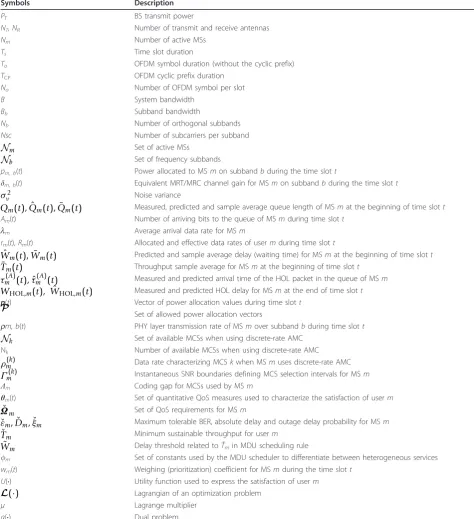
6.2 Comparing scheduling rules
The performance metrics versus traffic load for MSR, PF, EXP and MLWDF scheduling rules are compared in Figure 2 for an adaptive MIMO-OFDMA system serving
Nu = 20 RT users with the same average arrival rate.
The use of uniform power and CRA strategies over a 2
×2 MIMO system has been considered. Furthermore,
since the FC can be implemented with all scheduling rules, performance results have been obtained for each scheduling rule either with or without FC.
Without FC, the EXP and MLWDF rules provide the best joint results in terms of throughput, delay, Jain’s fairness indexes, and service coverage, with MLWDF achieving a slightly higher throughput, lower delay and better service coverage that EXP, at the cost of lower throughput and delay fairness indexes.cThe PF schedu-ler, although achieves a quite good result in terms of average throughput per flow, fails in providing QoS requirements. In fact, the PF rule can only guarantee a 99% service coverage for average arrival rates per flow less than 0.3 Mbps compared to the 0.8 and 1 Mbps that can be guaranteed by EXP and MLWDF rules, respectively. The MSR scheduling rule, which only con-siders CSI as a quality indicator, allocates all the resources to the users with favorable channel quality conditions, and those users experiencing bad channel quality conditions suffer from starvation. Hence, as it wastes resources, MSR rule is not capable of achieving queue stability and presents a very low average through-put and aninfinited average delay per flow, irrespective of the average traffic arrival rate.
Except for a slight increase in delay Jain’s fairness index, which is only perceptible for light or moderate traffic loads, the effect of implementing FC on the perfor-mance of EXP and MLDF scheduling rules is very small. This can be explained by the fact that, when calculating
the weighting coefficientswm(t), the EXP and MLDF
schedulers use QSI and thus, the performance gains pro-vided by the introduction of the FC are just incremental. On the contrary, the performance improvement induced by the implementation of FC is considerable for the PF rule, and specially important for the MSR scheduler, which do not use QSI when calculatingwm(t). In fact,
even though the PF and MSR rules provide poorer Jain’s fairness indexes than those delivered by the EXP and MLWDF rules, they can guarantee a 99% service cover-age for avercover-age arrival rates per flow less than approxi-mately 0.8 Mbps, which is almost the same that can be guaranteed when using the EXP scheduler.
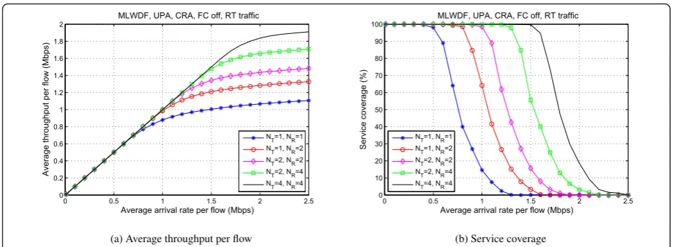
6.3 Comparing allocation strategies
Figure 3 shows the performance metrics versus traffic load for a MIMO-OFDMA system using MLWDF sche-duling rule and different combinations of UPA, APA, DRA and CRA strategies, with and without FC. A set of Nu= 20 RT users with the same average arrival rate has
been assumed. As it can be observed, APA-based strate-gies improve the performance of UPA-based ones. Nevertheless, this performance improvement, although noticeable for discrete rate-based systems, becomes almost negligible when using continuous rate-based schemes. This result suggests that using AMC schemes with a large set of modulation formats combined with powerful channel codes with adaptive coding rates can make unnecessary the use of power allocation strategies.
The effect of implementing FC on the system perfor-mance metrics is practically identical irrespective of the power and rate allocation strategies implemented at the cross-layer resource allocation unit. The average throughput per flow, delay, throughput JFI and service coverage are basically unaffected, and only an improve-ment in delay JFI is obtained with light and moderate traffic loads. Although not shown in the graphs, when implementing APA strategies, the use of FC also intro-duces a decrease in power consumption. This is due to the fact that resources (power and subbands) are only allocated when necessary, that is, when there is enough information in the queues ready to be transmitted.
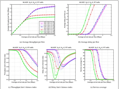
6.4 Comparing MIMO configurations
The effects of using different NT × NR MRT/MRC
power and CRA strategies, without FC, to serveNu= 20 RT users with the same average arrival rate. As it can be observed, increasing the number of transmit and/or receive antennas at the PHY can significantly improve the system capacity. In fact, the increase of NTand/or
NR translates into a widening of the stability region, which proves the convenience of employing MIMO spa-tial diversity at the PHY to support statistical QoS for upper layer protocols. For instance, Figure 4b shows that, using this particular configuration, a single trans-mit/receive antenna system can only guarantee a 99% service coverage for average arrival rates per flow less than 0.45 Mbps, compared to the 0.95 or 1.5 Mbps that
can be guaranteed by using 2×2 or 4×4 MIMO
con-figurations, respectively.
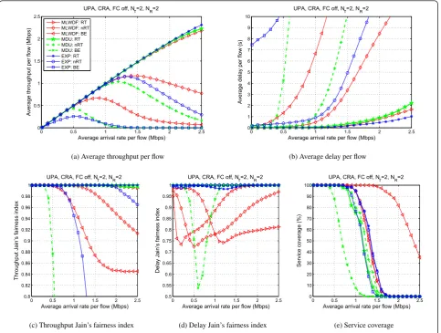
6.5 Performance results for heterogeneous traffic scenarios
Figure 5 shows the performance metrics versus traffic load for a MIMO-OFDMA system serving a set of
heterogeneous traffic flows. The behavior of three sche-duling rules, namely, MLWDF, EXP and MDU, are compared for a system implementing UPA and CRA, without FC. Simulations have been performed assuming that N(RT)
m =Nm(nRT)=Nm(BE)= 10users are always active
in the system. Furthermore, based on the required QoS of the different traffic flows, the parameters of the MDU
scheduler have been set to m = {1, 1.5} and
˜
Wm= 25 ms ms for RT users, m = {0.6, 1} and
˜
Wm= 500ms for nRT users and, finally, m = {0.5, 0}
andW˜m= 500ms for BE users. As it can be observed,
cross-layer scheduling and resource allocation strategies are able to fairly allocate resources among traffic classes, according to the assigned prioritiescm(t), obtained from the QoS requirements. Obviously, RT users, which exhi-bit stringent absolute delay requirements, tend to be allocated more resources than nRT and BE users as the arrival data rates increase. For the same reasons, nRT users are allocated more resources than BE users. The result is that, although for light traffic arrivals the three
0 0.5 1 1.5 2 2.5
0 0.2 0.4 0.6 0.8 1 1.2 1.4 1.6 1.8
Average arrival rate per flow (Mbps)
Average throughput per flow (Mbps)
UPA, CRA, N
T=2, NR=2, RT traffic
MSR, FC on MSR, FC off PF, FC on PF, FC off EXP, FC on EXP, FC off MLWDF, FC on MLWDF, FC off
(a) Average throughput per flow
0 0.5 1 1.5 2 2.5
0 0.5 1 1.5 2 2.5 3 3.5 4 4.5 5
Average arrival rate per flow (Mbps)
Average delay per flow (s)
UPA, CRA, N
T=2, NR=2, RT traffic
(b) Average delay per flow
0 0.5 1 1.5 2 2.5
0 0.1 0.2 0.3 0.4 0.5 0.6 0.7 0.8 0.9 1
Average arrival rate per flow (Mbps)
Throughput Jain’s fairness index
UPA, CRA, NT=2, NR=2, RT traffic
(c) Throughput Jain’s fairness index
0 0.5 1 1.5 2 2.5
0.1 0.2 0.3 0.4 0.5 0.6 0.7 0.8 0.9 1
Average arrival rate per flow (Mbps)
Delay Jain’s fairness index
UPA, CRA, NT=2, NR=2, RT traffic
(d) Delay Jain’s fairness index
0 0.5 1 1.5 2 2.5
0 10 20 30 40 50 60 70 80 90 100
Average arrival rate per flow (Mbps)
Service coverage (%)
UPA, CRA, NT=2, NR=2, RT traffic
(e) Service coverage
classes of service can achieve good performance figures, for moderate traffic arrivals, RT and nRT users can only maintain acceptable performance at the cost of a decrease in the performance of BE users. Furthermore, for heavy traffic arrivals, the performance of RT users can only be maintained by sacrificing that of nRT and BE users.
In this particular scenario, except for very heavy traffic arrivals, the MLWDF scheduling rule provides the best performance results in terms of average throughput per flow and service coverage at the cost of a worse beha-vior of the delay Jain’s fairness index. The MDU schedu-ler provides the best results in terms of both throughput and delay Jain’s fairness indexes for RT and nRT traffic classes, but such a fair behavior is obtained at the cost of service coverage. The EXP scheduler sacrifices the average throughput and delay per flow of BE users to obtain a good trade-off between service coverage and delay Jain’s fairness index.
7 Conclusions
The emergence of state-of-the-art and next-generation wireless communications networks based on adaptive MIMO-OFDMA PHY access schemes, will enable the support of a wide range of multimedia applications with heterogeneous QoS requirements. In order to optimize the resource utilization while maintaining the QoS pro-vided to as many users as possible, these systems require of adaptive scheduling and resource allocation algo-rithms able to grant a proper trade off between effi-ciency and fairness. In this context, using tools from information and queueing theories, mathematical convex programming, and stochastic approximation, a unified framework for channel- and queue-aware QoS-guaran-teed cross-layer scheduling and resource allocation algo-rithms has been developed in this article. The proposed unified framework generalizes previous work on this topic by encompassing different types of traffic, different utility functions measuring user’s satisfaction, uniform
0 0.5 1 1.5 2 2.5
0 0.2 0.4 0.6 0.8 1 1.2 1.4 1.6
Average arrival rate per flow (Mbps)
Average throughput per flow (Mbps)
MLWDF, N
T=2, NR=2, RT traffic
APA, CRA, FC off APA, CRA, FC on UPA, CRA, FC off UPA, CRA, FC on APA, DRA, FC off APA, DRA, FC on UPA, DRA, FC off UPA, DRA, FC on
(a) Average throughput per flow
0 0.5 1 1.5 2 2.5
0 0.5 1 1.5 2 2.5 3 3.5 4 4.5 5
Average arrival rate per flow (Mbps)
Average delay per flow (s)
MLWDF, N
T=2, NR=2, RT traffic
(b) Average delay per flow
0 0.5 1 1.5 2 2.5
0.93 0.94 0.95 0.96 0.97 0.98 0.99 1
Average arrival rate per flow (Mbps)
Throughput Jain’s fairness index
MLWDF, N
T=2, NR=2, RT traffic
(c) Throughput Jain’s fairness index
0 0.5 1 1.5 2 2.5
0.6 0.65 0.7 0.75 0.8 0.85 0.9 0.95 1
Average arrival rate per flow (Mbps)
Delay Jain’s fairness index
MLWDF, N
T=2, NR=2, RT traffic
(d) Delay Jain’s fairness index
0 0.5 1 1.5 2 2.5
0 10 20 30 40 50 60 70 80 90 100
Average arrival rate per flow (Mbps)
Service coverage (%)
MLWDF, N
T=2, NR=2, RT traffic
(e) Service coverage
and adaptive power allocation, continuous and DRA, and protocols with different amounts of channel- and queue-awareness. System parameters and QoS require-ments have been projected into utility functions, which have then been used to formulate a unified constrained utility maximization problem, whose main aim is to bal-ance the efficiency and fairness of resource allocation. Optimal solutions for this problem have been obtained for the UPA schemes, and novel quasi-optimal algo-rithms have been proposed for the APA strategies, exhi-biting complexities that are linear in the number of resource units and users.
The proposed unified optimization framework allows for a fair performance comparison of different schedul-ing rules, different allocation strategies, different MRT/ MRC-based MIMO configurations, and different traffic scenarios. Simulation results presented in this article have shown that:
- Without FC, the EXP and MLWDF rules provide the best joint performance results, with MLWDF achieving a slightly higher throughput, lower delay and better ser-vice coverage that EXP, at the cost of lower throughput and delay fairness indexes. The PF and MSR scheduling rules, which only consider CSI as a quality indicator, fail in providing QoS. However, although implementing FC has a negligible impact on the performance of EXP and MLDF scheduling rules, the performance improvement induced by FC is remarkable for the PF and MSR schedulers.
- APA-based strategies improve the performance of UPA-based ones. Nevertheless, this performance improvement, although noticeable for DRA systems, becomes almost negligible when using CRA schemes. Thus, using AMC schemes with a large set of modula-tion and coding formats can make unnecessary the use of power allocation strategies.
- Increasing the number of transmit and/or receive antennas at the PHY translates into a widening of the stability region, proving in this way the convenience of employing MIMO spatial diversity to support statistical QoS provision to upper layer protocols.
- Channel- and queue-aware cross-layer scheduling and resource allocation strategies can fairly allocate resources among heterogenous traffic classes, with dif-ferent scheduling policies (e.g., EXP, MDU and MLWDF) providing different trade-offs between effi-ciency, delay, fairness and service coverage.
Simulation results have demonstrated the validity and merits of the proposed cross-layer unified approach. However, the optimization problem treated in this arti-cle is only applicable to single cell scenarios using MRT/MRC-based MIMO techniques. Therefore, to widen its application scope, current work focusses on extending the cross-layer unified approach to distributed scheduling and resource allocation in generalized MIMO-OFDMA multicellular wireless heterogeneous networks, possibly including more sophisticated MIMO techniques, one- and two-way relays, shared relays, femto-cells and/or clusters of coordinated BSs.
Endnotes
a
LTE was introduced in 3GPP Releases 8 and 9 as a major step forward for UMTS-based networks, and LTE-Advanced is the fourth generation (4G) LTE stan-dard in 3GPP Release 10.
b
A scheduling algorithm is said to be throughput opti-mal if it can keep all the queues stable if this is at all feasible to do.
c
Typically, the delay Jain’s fairness index is high for light traffic arrival rates because, in this case, all the flows can be served after very low average waiting times in the queues. For moderate traffic arrival rates, the
0 0.5 1 1.5 2 2.5
0 0.2 0.4 0.6 0.8 1 1.2 1.4 1.6 1.8 2
Average arrival rate per flow (Mbps)
Average throughput per flow (Mbps)
MLWDF, UPA, CRA, FC off, RT traffic
NT=1, NR=1 N
T=1, NR=2 NT=2, NR=2 NT=2, NR=4 NT=4, NR=4
(a) Average throughput per flow
0 0.5 1 1.5 2 2.5
0 10 20 30 40 50 60 70 80 90 100
Average arrival rate per flow (Mbps)
Service coverage (%)
MLWDF, UPA, CRA, FC off, RT traffic
NT=1, NR=1 N
T=1, NR=2 NT=2, NR=2 NT=2, NR=4 NT=4, NR=4
(b) Service coverage