R E S E A R C H
Open Access
Impacts of impulsive noise from partial
discharges on wireless systems performance:
application to MIMO precoders
Ghadir Madi
1, Fabien Sacuto
3, Baptiste Vrigneau
1*, Basile L Agba
2, Yannis Pousset
1, Rodolphe Vauzelle
1and
François Gagnon
3Abstract
To satisfy the smart grid electrical network, communication systems in high-voltage substations have to be installed in order to control equipments. Considering that those substations were not necessarily designed for adding communication networks, one of the most appropriate solutions is to use wireless sensor network (WSN). However, the high voltage transported through the station generates a strong and specific radio noise. In order to prepare for such a network, the electromagnetic environment has to be characterized and tests in laboratories have to be performed to estimate the communication performances. This paper presents a method for measuring the noise due to high voltage and more particularly the impulsive noise. In the laboratory, we generate the impulsive noise using two specimens, and we show that these laboratory measurements validate the field measurements of Pakalaet al. For the two specimens, it aims to link the noise characteristics (magnitude and frequency) with the specimen parameters (power supply and geometric dimensions) to predict the environments where wireless communications can be troublesome. By using different sets of this measured noise, we show that the statistical model of Middleton Class A can be used to model the impulsive noise in high-voltage substations better than the Gaussian model. We consider a cooperative multiple-input-multiple-output (MIMO) system to achieve the wireless sensor communication. This system uses recent MIMO techniques based on precoding like max-dminand P-OSM precoders. The MIMO precoder-based cooperative system is a potential candidate for energy saving in WSN since energy efficiency optimization is a very important critical issue. Since MIMO precoders are with Gaussian noise assumption, we evaluate the performance of several MIMO precoders in the presence of impulsive noise using estimated parameters from the measured noise.
Keywords:MIMO, precoders, impulsive noise, high-voltage substations modeling
I. Introduction
In order to save energy, electricity providers have attempted to control and monitor their grid using “smart grid” regulation [1]. It consists, for example, of knowing the needs of electric equipments in consumers’ home and adapting the transformation of energy from high-voltage substation. The first step is to interact with those substations by checking equipment status using sensor network technology. It is important to keep in mind that current substations will still be operational
for the next 50 years, and because of their large area, it would be very expensive to link sensors with optical fiber or cables. Therefore, one of the most appropriate solutions is to adapt a wireless network to those substa-tions. Since wireless networks do not use expensive sig-nal and control cables for data transmission, they are easier to install and provide a cost-effective solution for these applications. However, there is a concern: the pre-sence of impulsive noise or electromagnetic interference (EMI) generated by high-voltage equipments. According to Pakala measurements [2,3] going from DC to 10 GHz, the noise power near wireless communication fre-quencies is significant (around -50 dBm average power for the band 1-10 GHz). We have to distinguish two
* Correspondence: [email protected]
1
XLIM-SIC UMR CNRS 6172 Bvd., Marie et Pierre Curie, 86962 Futuroscope Cedex, France
Full list of author information is available at the end of the article
noises: the ambient noise that is considered Gaussian and the impulsive noise. The impulsive noise is mainly due to partial discharges which occurs within high-vol-tage equipment or on its surface. The impulsive noise has a highly structured form characterized by significant probabilities of large interference levels and short dura-tion [4]. The impulsive character of the interference can drastically degrade the performance and the reliability of wireless communication systems even in case of high signal-to-noise ratios. In order to guard against unaccep-table performance, the true characteristics of the noise must be taken into account. To do so, one needs an accurate model for the impulsive noise.
Statistical-physical models of EMI have been derived by Middleton with three models (class A, B, and C) including the non-Gaussian components of natural and man-made noise [5]. The models are parametric with parameters explicitly determined by the underlying phy-sical mechanisms and are canonical, i.e., their mathema-tical form is independent of the physical environment. The distinction between the three models is based on the relative bandwidth of noise and receiver. Middleton models have been shown to accurately model the non-linear phenomenon governing electromagnetic interfer-ence. These models have been widely used in electro-magnetic applications and communication problems [4,6,7].
As mentioned before, a wireless network seems to be a good solution in a large area where electricity substa-tion is situated. Therefore, our research focuses on the wireless sensor communication in this environment. There has recently been a great amount of research on various MIMO techniques for wireless communication systems; more particularly, cooperative MIMO and vir-tual antenna array concepts have been proposed to achieve MIMO capability in WSN [8,9]. The goal is to reduce the energy consumption of sensors since energy efficiency optimization is a very important critical issue in system design of WSN. The results have shown that in some cases, MIMO-based cooperative systems for WSN lead to better energy optimization and smaller end-to-end delay compared to the traditional single-input single-output (SISO) approach even after taking into account the additional circuit power, communica-tions, and training overheads [10]. These cooperative systems were based on space-time block codes (STBC). Therefore, we consider a MIMO system to achieve the wireless sensor communication in the substation. The idea is to exploit more the performance of MIMO sys-tems by using recent MIMO techniques based on pre-coding like MIMO max-dmin[11] and P-OSM precoders
[12]. MIMO precoders require the knowledge of the channel state information (CSI) at the transmitter. The precoder exploits the CSI to improve the performance
of a wireless system by optimizing a pertinent criteria. MIMO precoders improve the BER and increase the spectral efficiency of the system compared to STBC codes. Therefore, the MIMO precoder-based cooperative system is a potential candidate for more energy saving design in WSN, and we will propose many cooperative schemes for these precoders in a future work. A wireless MIMO precoder-based cooperative system will suffer from the impulsive noise in the substation. In this work, the precoder does not represent a solution against the impulsive noise, but it is rather used as a promising technique for energy-efficient data transmission in WSN. In digital subscriber line (DSL) communication, various solutions are applied to mitigate the effects of impulsive noise. In [13], a variety of error control tech-niques are discussed. They are focused on enhancing the Reed-Solomon code performance. The application of Turbo-Codes is also considered in [14]. Other solutions can be applied to combat the impulsive noise effects like a non-linear receiver [4,15]. The non-linear receiver needs the knowledge of a statistical model of the noise. All these mentioned solutions could be applied to the wireless MIMO precoder-based cooperative system to improve it, but one may first need to define a standard for this system in order to choose the appropriate solu-tion. However, we show later that if we know the statis-tical model of the impulsive noise in the substation, the maximum likelihood (ML) MIMO receiver could lead to a certain improvement in performance. Therefore, before installing this type of wireless system in substa-tions, the electromagnetic environment should be heav-ily studied, and tests in laboratories should be performed in order to characterize the noise and evalu-ate its effects on the wireless system.
In this paper, we present a method for measuring par-tial discharges of two specimens in the laboratory and then analyze the parameters affecting wireless communi-cations. Results show that these laboratory measure-ments of partial discharges validate the field measurements in [2]. From these measurements, our goal is to validate the statistical model of Middleton Class A for the high-voltage substation. Since Middleton Class A model was derived for single-antenna systems, an extension of the model is derived for multi-antenna systems. This validation allows us to consider a statisti-cal model for the impulsive noise of partial discharges in order to evaluate its impact on a MIMO precoder wireless transmission system in a high-voltage substation (in the presence of impulsive noise).
impulsive noise spectrum. Section III introduces a brief overview of the Middleton Class A model and focuses on the validation of this model with the measured data of partial discharges, and the extension of Middleton Class A model for multi-antenna systems is also pre-sented. The MIMO precoders used in simulation are presented in Section IV. Performances in terms of bit error rate (BER) of MIMO precoders are evaluated in Section V. The BER of MIMO precoders is evaluated in the presence of impulsive noise modeled by Middleton Class A and compared to the BER in the presence of Gaussian noise. Finally, we draw the conclusion in Sec-tion VI.
II. Measurements of partial discharges A. Measurement method
Two specimens are used to generate partial discharges, a generator bar and a Tesla-coil [16]. For the generator bar, a copper conductor is coated with epoxy-micarta insulation with a shield covers the insulation in the middle of the bar. This specimen can be considered as an unsheathed coaxial cable: The central conductor is linked to a high-voltage source, and the shield is grounded. The Tesla-coil is a tool used to ionize plasma. It delivers a high voltage (54 kV). The same measurement setup is used for the two specimens. A wideband antenna is linked to the TDS6124C digital oscilloscope, which is set with a sampling frequency twice larger than the maximum frequency of the antenna. For example, 2.5 GS/s sampling frequency is used when the biconical antenna (30-300 MHz) is used, and 10 GS/s is used for the Wi-Fi antenna (2.4 GHz, 2 dBi). The step-by-step procedure for the measurements is described as follows:
• Step 1: The antenna is installed at 2 m approxi-mately from the specimen. The antenna is connected to an oscilloscope, located behind a Faraday fence. • Step 2: Before feeding current into the specimen, the electromagnetic noise of the room must be mea-sured and recorded.
•Step 3: The fence is closed, and then the specimen is fed gradually from 1 kV until the first discharge waveform appears on the oscilloscope.
• Step 4: The oscilloscope trigger must be set to record partial discharges as soon as they appear. (Setting the trigger above twice magnitude of the background noise is recommended).
• Step 5: Once the waveform is captured, it is recorded in a file and exported for processing. • Step 6: The FastFrame option [17] can be used to record 50 or 100 partial discharge waveforms for sta-tistical analysis (the FastFrame waveform is also recorded in a file).
•Step 7: Statistical analysis is done using MATLAB signal processing tool.
B. Specimen parameters influence
1) Magnitude rising
With the generator bar, it was observed in the labora-tory that the voltage used to feed the specimen has an influence on the partial discharge magnitude. The phe-nomenon has already been studied for different high-voltage substations [2,3,18]. For example, the power line with the highest voltage gives the more significant cor-ona noise according to Pakala works. So it is obvious that to obtain a more powerful partial discharge signal, we have to feed the specimen with a higher voltage which is not always possible in laboratory.
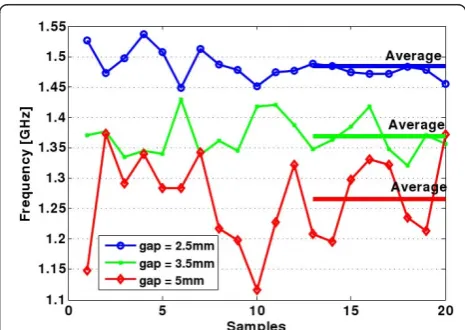
2) Average frequency rising
Considering that the distance between two electrodes under high voltage can influence the spectrum in power magnitude, it is predictable that this gap can also modify the frequency band of the partial discharge noise. Know-ing that this noise spectrum covers several hundreds of MHz for the Tesla-coil, we determine the average fre-quency associated with the noise signal as:
fave=
N
i=1
fi×
Si
N
j=1Sj
(1)
whereSiis the spectral magnitude of thefifrequency, andNis the number of spectrum points. With this for-mula and by varying the gap, we try to demonstrate the influence of the gap on the frequencies appearing in the spectrum.
Using each partial discharge spectrum, the average fre-quency is calculated for different gaps (5, 3.5, and 2.5 mm). Figure 1 shows the gap influence on average
frequency for 20 partial discharges recorded (samples). Obviously, the average frequency rises when the gap gets small. From (1), it is seen that the spectrum com-ponents (Si) are greater for a small gap. The impulsive noise band thus moves toward the communication bands (900 MHz, 2.4 GHz, 5-6 GHz) with a smaller gap size.
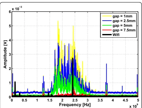
Considering this fact, a test bed is set up in order to observe what is the behavior of the impulsive noise spectrum around 2.4 GHz (Figure 2). To analyze the impact of the impulsive noise to a 2.4 GHz communica-tion signal, a Wi-Fi router is operating during the experiences, and its signal serves as a reference. It is placed at 14 m from the antenna. The signal at 2.4 GHz is amplified about 25 dB by the LNA amplifier. Hence, the oscilloscope records signals around 2.4 GHz. The Wi-Fi antenna is at distance of 10 m from the partial discharge. The average spectrum of Figure 3 is calcu-lated based on the recording of 100 partial discharges for different gaps in Tesla-Coil setup. From Figure 3, it is obvious that the frequencies of Tesla-Coil overlap the Wi-Fi signal, and by observing the spectrum corre-sponding to 2.5 mm gap, it is also obvious that the Wi-Fi transmission can be significantly degraded.
Consequently, the impulsive noise can interfere with the communication bands, if the voltage is high enough and the gap small enough. Indeed, the voltage delivered by the specimens in our measurements is well below the voltage of high-voltage substations (200-700 kV). Partial discharges occur more easily in substations because the air dielectric strength can be reached by higher voltage and for bigger gap than we used (360 kV for a 10 cm gap for example).
III. Statistical model of measurements and noise model for multi-antenna system
In this section, we will validate the statistical model of Mid-dleton Class A with the measured data of partial discharges obtained in Section II. Here, we do not focus on the frequency of the noise. We first present a brief overview of the Middleton Class A model. Then, we focus on the validation of this model with the measured
data and the extension of Middleton Class A model for multi-antenna system.
A. Middleton Class A model
Middleton Class A model refers to Narrowband Noise where interference spectrum is narrower than the recei-ver bandwidth. In this model, the received interference is assumed to be a process having two components [4,5]:
X(t) =XP(t) +XG(t) (2)
where XP(t) and XG(t) are independent processes. They represent the non-Gaussian (impulsive) and Gaus-sian components, respectively. The probability density function (PDF) ofX(t) is given in [4]:
Note thatfis a weighted sum of zero-mean Gaussians with increasing variance. Aand Γ are the basic para-meters of the model. Let us consider their definitions and physical significance:
1)Ais the Overlap Index or Nonstructure Index.
A=vTs (4)
where vis the average number of emission events impinging on the receiver per second and Ts is the mean duration of a typical interfering source emission. The smaller A is, the fewer the number of emission (events) and/or their durations. Therefore, the (instanta-neous) noise properties are dominated by the waveform
Figure 22.4 GHz measurement setup.
0 0.5 1 1.5 2 2.5 3 3.5 4 4.5 5
characteristics of individual events. AsAis made larger, the noise becomes less structured, i.e., the statistics of the instantaneous amplitude approach the Gaussian dis-tribution (according to central limit theory [5]). Hence,
Ais a measure of the non-Gaussian nature of the noise input to the receiver.
2) Γ is called the Gaussian factor. It is the ratio of powers in the Gaussian and non-Gaussian components
= (XG) (XP)
(5)
In general, A Î [10-4, 1] and Γ Î [10-6, 1] [19]. By adjusting the parametersAandΓ, the density in (3) can be made to fit a great variety of non-Gaussian noise densities.
B. Validation of Middleton Class A model for partial discharge
We validated the Middleton Class A model with the measured datasets presented previously by the following procedure of Figure 4. From the measured noise, we used the method of moments [20] to estimate the para-metersAandΓof Middleton Class A model:
Aest=
sixth order moments of the envelope data respectively. These estimated parameters will then be used to gener-ate the noise. In the procedure for validation, three sta-tistical methods are used to compare measured and simulated noises:
1) The probability density function (PDF) is estimated from measured data by using kernel density estimators [21].
2) The complementary cumulative distribution func-tion (CCDF) gives the probability that the random vari-able is above a particular level and is defined as:
CCDF(X) =P(X>x) = ∞
x
PDF(u)du= 1−CDE(x) (8)
where CDF is the cumulative distribution function. 3) The Kullback-Leibler divergence (K-L) is a relative entropic criterion, and it measures the dissimilarity between two probability distributions P and Q, where (K-L) = 0 indicates thatP=Q[22,23].
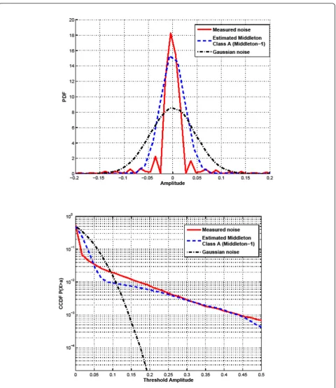
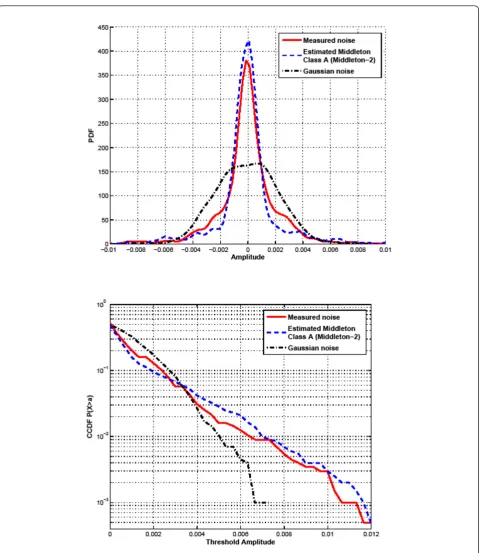
Figures 5 and 6 show both PDF and CCDF for two measured noises (generator bar and Tesla-Coil), respec-tively. The estimated parameters for the two measured noises are (Aest = 0.0280, Γest = 0.3978) for generator
bar and (Aest= 0.3575,Γest= 0.1194) for Tesla-Coil. We
denote Middleton-1 and Middleton-2 the estimated Middleton class A noise calculated using the estimated parameters (Aest = 0.0280, Γest = 0.3978) and (Aest=
0.3575,Γest= 0.1194), respectively. The PDF and CCDF
of the estimated Middleton class A noises and the Gaus-sian noise are also presented on Figures 5 and 6. These figures show that the PDF and CCDF of the estimated Middleton class A noises (Middleton-1and Middleton-2) are more close to the measured noises than the Gaus-sian case. Table 1 confirms these observations by pre-senting the K-L divergences of the measured noises and the two models of noise (Middleton and Gaussian). So, the K-L divergence of Measured noise-1 density is 0.04 from the estimated Middleton Class A density and 0.3 from the Gaussian density. For Measured noise-2 den-sity, the K-L divergence is 0.02 from the estimated Mid-dleton Class A density and 0.27 from the Gaussian density. These results confirm that the measured impul-sive noise is better modeled by the Middleton Class A model as compared to Gaussian noise. Hence, we can use the Middleton Class A as an approximated model for impulsive noise in high-voltage substation. There-fore, we evaluate the performance of wireless communi-cation in this environment using the estimated parameters of the measured noises.
C. Extension of Middleton Class A model for multi-antenna systems
In order to evaluate the performances of MIMO systems under the impulsive noise, an extension of the Middle-ton model is derived. MiddleMiddle-ton Class A model was derived for single-antenna systems. For a two-antenna system, we considered a bivariate Middleton Class A model used in [7]. This model is limited to nr = 2 antennas. Thus, we derive an extension for nr ≥2. We can write (3) as:
Estimation ofAandΓ
Simulated noise
Comparison
PDF, CCDF
PDF, CCDF Middleton Class A
where am=
e−AAm
m! ,μ= 0 and
g(x,σm2) = 1 2πσ2
m
e
−x2
2σ2
m. The density of Middleton
Class A can be approximated by the two-term model [19]:
f(x) =e−Ag(x,σ02) + (1−e−A)g(x,σ12) (10)
Let x = [x1,x2,x3, ...,xk] be a vector ofk=nrrandom variables, each variable has a Middleton Class A density function and xk is the noise observation at the kth antenna. Then, the multivariate density of x can be
Figure 6Measured noise-2 (Tesla-Coil) PDF and CCDF.
Table 1 K-L Divergences
Measured noise-1 Measured noise-2
Class A 0.04 0.02
written as [19]: represents the spatial correlation in the noise andgis a multivariate Gaussian function:
where |.| denotes the determinant. From (11) and (12), we obtain:
Equation (13) represents a general extension of Mid-dleton Class A model for multi-antenna systems. We can use the approximation as in (10). Then, we obtain an approximate version of the extension:
fx(x) = the correlation coefficient between the noise observa-tions at i and jantennas, -1 ≤ r ≤ 1. Finally, we can
IV. MIMO systems used in simulation A. MIMO precoders
As mentioned in the introduction, the MIMO system used is based on precoding with the assumption that the CSI is available at both transmit and receive sides. The use of CSI allows designing precoders by optimiz-ing a pertinent criteria as maximizoptimiz-ing the received sig-nal-to-noise ratio (max-SNR or beamforming), minimizing the mean square error (MMSE), maximizing the capacity (Water-Filling solution) [24], or the maxi-mization of the minimum Euclidean distance of received constellation (max-dminsolution) [11]. All these linear
precoders are based on the singular value decomposition (SVD) of the channel matrix. The max-dmin precoder
achieves good performances in terms of BER providing a significant gain of SNR compared to the other preco-ders (max-SNR, MMSE, and Water-Filling) [25], and it will be used in our MIMO system.
Let us consider a MIMO system withnttransmit and
nr receive antennas over which we want to achieveb independent data streams (b≤min(nt,nr)). The received signal can then be expressed as:
y=GHFs+Gv (17)
where y is the b × 1 received vector, s is the b × 1 symbols vector of the constellation C, v is an additive noise vector of sizenr× 1,His the channel matrix, and
FandGare the precoder and decoder matrices, respec-tively. In our case, the additive noise is the Middleton Class A model.
B. Presentation of selected precoders
The precoder is presented using a virtual transformation of the system in (17) [11]. By considering the following decompositionsF =FvFd andG=GdGv, the input-out-put relation (17) can be re-expressed as:
y=GdHvFds+Gdvv (18)
This procedure is frequently used for MIMO linear precoder systems, and it is based on the SVD of the channel matrix H[11,24]. The matrix Hv= GvHFv = diag(s1, ...,sb) is the virtual channel matrix of sizeb×
b, si stands for every subchannel gain (sorted by decreasing order),vv =Gvvis the virtual noise, Gvand
Fvare unitary matrices obtained from applying the SVD operation on the channel matrix. Fd and Gdare b ×b matrices, representing the precoder and decoder in the virtual channel. The power constraint is expressed as
trace{FF∗}= trace{FdF*d} =p0, where p0 is the mean
considered in the rest of the paper, the decoder matrix Gd has no impact on the performance and is conse-quently assumed to be equal toIb, the identity matrix of sizeb ×b[11].
The max-dmin precoder maximizes the minimum
Euclidean distance between signal points at the receiver sidedminwhich is defined by:
dmin(Fd) = min
(sk,sl)∈Cb,sk=sl
HvFd(sk−sl) (19)
whereskandslare 2 symbol vectors whose entries are elements ofC. Then, the max-dminprecoder is the
solu-tion of:
Fd= arg max Fd
dmin(Fd) (20)
A very exploitable solution of (20) is given in [11] for two independent data streams,b= 2 and a 4-QAM with a spectral efficiency of 4 bit/s/Hz. Recently, the solution with two 16-QAM symbols was also given [26]. This extension permits to increase the spectral efficiency to 8 bit/s/Hz. The max-SNR precoder consists in maximizing the SNR and transmitting one single symbol. The mod-ulation is chosen in order to maintain the same spectral efficiency.
We will also use another linear precoding system pro-posed in [27] named ARITH-BER precoder. This preco-der minimizes the average BER or the arithmetic mean of the BER (ARITH-BER). It is based on the Schur-con-vex optimization.
There are other precoding design studied in the litera-ture, for example, the P-OSM precoder. This precoder uses a new orthogonal spatial multiplexing (OSM) scheme transmitting two independent data streams (b= 2) [12,28]. The P-OSM precoder maximizes the mini-mum distance like the max-dminbut it is not based on
the SVD operation. It simplifies the ML detection by searching for a single symbol (called single symbol decodable), while the ML in max-dmin requires
search-ing a pair of symbols. However, the P-OSM precoder assumes nt= 2 transmit antennas and whennt > 2, it should be associated with an antenna-selection scheme.
V. Simulation results
The performance of MIMO precoders presented in Sec-tion IV is evaluated in terms of BER in the presence of impulsive noise. The parametersA andΓ estimated in Section III-B were used to generate the corresponding noise. In measurement setup, single antenna is used to capture the impulsive noise, and we do not have yet measures fornrreceive multi-antenna configuration. In the noise model for multi-antenna system presented in III-C, we need the Gaussian factor Γ at each receive
antenna and the correlation coefficient r between the noise observations at receive antennas. These two para-meters can be estimated from measuring the noise in a multi-antenna configuration. Therefore, in order to launch simulation with the noise model for multi-antenna system, we assume a simple case:
(est=1=2=· · ·=nr) and there is no correlation between noise observations at antennas (-1≤r ≤1, we putrij=rji= 0). The Middleton Class A model is defined for only real sample observation. For complex signals (QAM modulation), we assume that the real and the ima-ginary parts of the signal are independent and identically distributed (i.i.d). A flat Rayleigh-fading channel was used, i.e.,His an (nr×nt) channel matrix with independent and identical distributed complex Gaussian entries with mean zero and unit variance. We simulated the MIMO preco-ders in several cases: with 4-QAM or 16-QAM, (2 × 2), (2 × 4) or (4 × 4) MIMO systems.bis always equal to 2 sym-bols in max-dmin, ARITH-BER and P-OSM precoders,
while it is equal to 1 in max-SNR precoder.
We consider an ML MIMO receiver. MIMO receivers have been typically designed under the assumption of additive white Gaussian noise. In our work, the wireless system is envisaged to work in electricity substations where the impulsive noise is prevalent. Thus, we first eval-uate the performances of MIMO systems in the presence of impulsive noise using the ML receiver with Gaussian noise assumption (ML-GN). Next, we apply an ML recei-ver with the assumption of impulsive noise (ML-IN). The goal is to see whether we can get an important improve-ment in performance between the two cases which could justify the use of such a receiver since its application is more complex than the ML-GN one as we will see later.
A. ML under Gaussian noise assumption: ML-GN
Figure 7 shows a degradation of BER of the max-dmin
precoder (2 × 2 and 2 × 4 MIMO) in the presence of impulsive noise (Middleton-1and Middleton-2). The energy of the Middleton Class A model is a sum of two components of noise (Gaussian and impulsive). At low SNR, the BER is sensitive to the Gaussian component of the Middleton Class A noise, which has lower energy than a classical Gaussian noise. Hence, BER of Middle-ton Class A is better compared to classical Gaussian noise at low SNR. At high SNR, the MIMO system becomes sensitive to the impulsive component, and this degrades the performance of the wireless systems in EMI (SNR loss can reach 5 dB). The BER of Middleton-1 noise is more degraded than Middleton-2case since the parameterAof Middleton-1is smaller than that of
Middleton-2. When the value of Aest increases, the
also shows the influence of the number of receive anten-nas. When we increased nr from 2 to 4, the BER is improved with a SNR gain near 4 dB. We can also observe that the impulsive noise influences the diversity order. Indeed, the max-dminprecoder achieves the
maxi-mum diversity ordernt×nrin the Gaussian case. In the Middleton case, the diversity is lower.
For 2 × 2 MIMO system and a perfect or imperfect CSI, we showed in [29] that the max-dmin16-QAM
pre-coder achieved a better BER than the max-SNR (256-QAM) one with a spectral efficiency of 8 bit/s/Hz and for Gaussian noise. This performance of max-dmin
16-QAM is also similar for 4 × 4 MIMO and Gaussian noise. Hence, we evaluated the performance of these precoders with 4 × 4 MIMO system, and in the pre-sence of impulsive noise, the performance of P-OSM and ARITH-BER is also evaluated. Figure 8 shows the BER for max-dmin, max-SNR, P-OSM and ARITH-BER
precoders for only Middleton-1. The max-dmin is still
better than the max-SNR. The BER of max-dminis
smal-ler than the BER of P-OSM at low and high SNR. The ARITH-BER seems to have a slight improvement com-pared with max-dminprecoder. However, for a certain
SNR (15 dB), the BERs of all precoders are close. It means that they are sensitive to the transition of the impulsive noise with a particular SNR.
B. ML under impulsive noise assumption: ML-IN
The detection rule for the ML receiver is given as
ˆ
s = arg max s∈C
{L(s|y)} (21)
In Gaussian noise, the likelihood function is expressed as the distance between the received signal and candi-date points in the constellation (distance metric). In Middleton Class A noise, this distance can not be attained. For this ML receiver, we use the probability density function of the Middleton noise model for multi-antenna systems given in (14). In this case, The ML detection can be expressed as the maximizing of the likelihood functionL(s/y)
ARITH-BER precoders with the ML-IN receiver (under impulsive noise assumption). The performance of this ML-IN receiver is significantly better (gain of 7 dB) than the ML-GN one. However, in case of P-OSM precoder, the ML-IN receiver is no longer single symbol decod-able. It now searches a pair of symbols like the
max-dmin, and ARITH-BER because the ML-IN receiver is
only possible for a joint ML detection.
The ML-IN receiver seemed to present an important gain of SNR (7 dB) compared to ML-GN receiver. This gain may be very useful in a cooperative MIMO for WSN in substation environments. Since the reduction of SNR ratio while still ensuring the same target BER leads to save the power consumption in WSN by
0 5 10 15 20 25
Middleton−1, 2x2 Middleton−2, 2x2 Gaussian, 2x2 Gaussian, 2x4 Middleton−1, 2x4 Middleton−2, 2x4
Figure 7BER of max-dmin, b = 2 symbols 4-QAM, 2 × 2 and 2
Figure 8BER of max-dmin, P-OSM, ARITH-BER,b= 2 symbols
reducing the transmission energy [9]. However, the computational complexity of this receiver is higher than its ML-GN counterpart. Furthermore, it requires the knowledge of the noise model parameters (A andΓ). Therefore, this receiver should be associated with an estimator of noise parameters, or the electromagnetic environment should be heavily studied, and tests in laboratories and in sites should be performed in order to characterize the noise and its parameters.
VI. Conclusion
The works presented deal with the modeling of an impulsive noise in a high-voltage substation and its impacts on promising MIMO techniques such as linear precoding. The specimens used in this study reveal that the methodology for measuring impulsive electromag-netic noise is valid for any kind of air partial discharges. The applied voltage and the physical dimensions (gap) have a direct influence on the impulsive noise spectrum: a high voltage and a small gap can move the average frequency to the high frequencies (above 1 GHz). More-over, the statistical modeling of the measurements showed that Middleton Class A can be used as an approximated model for impulsive noise in high-voltage substations. Using the estimated parameters of the mea-sured noise and the MIMO extension of the Middleton model, we have evaluated the performance of several MIMO precoders with channel state information at both transmitter and receiver. At a high SNR, the per-formance of precoders was degraded in the presence of impulsive noise compared to Gaussian one. The ML-IN receiver, i.e. under an impulsive noise assumption, seemed to present an important gain (7 dB), but the complexity is increased. For future works, we recom-mend to do some additional measurements with a
higher voltage (up to 200 kV in laboratory and more in substations) and extend the focus around ISM bands to other wireless technologies like ZigBee, Wimax, or LTE. It will also be interesting to validate the multi-antenna extension model with measured data noise using nr antennas in measurement setup as in a MIMO configuration.
Acknowledgements
This work has been done in a scientific collaboration between XLIM-SIC laboratory (France), Hydro-Québec’s Research Institute, and École de technologie supérieure (Canada) as part of project for wireless sensors communication in disturbed environments. It was supported by the Samuel De Champlain program between France and Québec.
Author details
1XLIM-SIC UMR CNRS 6172 Bvd., Marie et Pierre Curie, 86962 Futuroscope
Cedex, France2Institut de Recherche d’Hydro-Québec, 1800 Lionel-Boulet, Varennes, QC, J3X-1S1, Canada3École de technologie superieure, 1100
Notre-Dame ouest, Montréal, QC, H3C-1K3, Canada
Competing interests
The authors declare that they have no competing interests.
Received: 26 February 2011 Accepted: 25 November 2011 Published: 25 November 2011
References
1. GW Arnold, Challenges and opportunities in smart grid: a position article. Proc IEEE.99(6), 922–927 (2011)
2. W Pakala, V Chartier, Radio noise measurements on overhead power lines from 2,4 to 800 kv. IEEE Trans Power Appl Syst.PAS-90, 1155–1165 (1971) 3. W Pakala, E Taylor, R Harrold, Radio noise measurements on high voltage lines from 2.4 to 345 kv. IEEE Trans Electromagn Compat.10, 96–107 (1968) 4. A Spaulding, D Middleton, Optimum reception in an impulsive interference
environment-part 1: coherent detection. IEEE Trans Commun, 9: 910–923 (1977)
5. D Middleton, Non-gaussian noise models in signal processing for telecommunications: new methods and results for class A and class B noise models. IEEE Trans Inf Theory.45(4), 1129–1149 (1999). doi:10.1109/ 18.761256
6. S Miyamoto, M Katayama, N Morinaga, Performance analysis of QAM systems under class A impulsive noise environment. IEEE Trans Electromagn Compat.37(2), 260–267 (1995). doi:10.1109/15.385891
7. K Gulati, A Chopra, R Heath, B Evans, K Tinsley, X Lin, MIMO receiver design in the presence of radio frequency interference, inIEEE Globecom(2008) 8. S Cui, AJ Goldsmith, A Bahai, Energy-efficiency of MIMO and cooperative MIMO techniques in sensor networks. IEEE J Sel Areas Commun.22(6), 1089–1098 (2004). doi:10.1109/JSAC.2004.830916
9. SK Jayaweera, Virtual MIMO-based cooperative communication for energy-constrained wireless sensor networks. IEEE Trans Wireless Commun.5(5), 984–989 (2006)
10. M Islam, K Jinsang, On the cooperative MIMO communication for energy-efficient cluster-to-cluster transmission at wireless sensor network, inAnn Telecommun, vol. 65. (Springer, Paris, 2010), pp. 325–340. doi:10.1007/ s12243-009-0151-9
11. L Collin, O Berder, P Rostaing, G Burel, Optimal minimum distance-based precoder for MIMO spatial multiplexing systems. IEEE Trans Signal Process.
52(3), 617–627 (2004). doi:10.1109/TSP.2003.822365
12. Y Kim, H Lee, S Park, I Lee, Optimal precoding for orthogonalized spatial multiplexing in closed-loop MIMO systems. IEEE J Sel Areas Commun.26(8), 1556–1566 (2008)
13. TN Zogakis, PS Chow, JT Aslanis, JM Cioffi, Impulse noise mitigation strategies for multicarrier modulation, inProc IEEE Int Conf Commun, vol. 2. Geneva, pp. 784–788 (1993)
14. T Faber, T Scholand, P Jung, On turbo codes for environments impaired by impulsive noise, inVehicular Technology Conference, VTC2004-Fall(2004)
0 5 10 15 20 25
15. FH Gregorio, JE Cousseau, JL Figueroa, Reducing impulsive noise in DSL systems -robustness and delay, inProceedings of the 6th Nordic Signal Processing Symposium–NORSIG(2004)
16. http://www.electrotechnicproduct.com/pinhole.asp
17. I Moore, I Portuguks, A Glover, A non-intrusive partial discharge
measurement system based on RF technology, inPower Engineering Society General Meeting, IEEE(2003)
18. T Babnik, R Aggarwal, PJ Moore, Z Wang, Radio frequency measurement of different discharges. inIEEE Bologna PowerTech Conference23–26 (June 2003)
19. PA Delaney, Signal detection in multivariate class A interference. IEEE Trans Commun.43(2), 365–373 (1995). doi:10.1109/26.380055
20. D Middleton, Procedures for determining the properties of the first-order canonical models of class A and class B electromagnetic interference. IEEE Trans Electromagn Compat.21, 190–208 (1979)
21. ZI Botev, A novel nonparametric density estimator. The University of Queensland, Tech Rep (2006)
22. S Kullback,Information Theory and Statistics(Peter Smith, Gloucester, 1978) 23. M Basseville, Information: entropies, divergences and mean values. IRISA
1020, Rennes France: Institute of Research in Computer Sciences and Random Systems. (1996)
24. H Sampath, P Stoica, A Paulraj, Generalized linear precoder and decoder design for MIMO channels using the weighted MMSE criterion. IEEE Trans Commun.49(12), 2198–2206 (2001). doi:10.1109/26.974266
25. B Vrigneau, J Letessier, P Rostaing, L Collin, G Burel, Statistical comparison between max-dmin, max-SNR and MMSE precoders, in40th Asilomar Conference on Signals, Systems and Computers(2006)
26. Quoc-tuong, O Berder, B Vrigneau, O Sentieys, Minimum distance based precoder for MIMO-OFDM systems using a 16-QAM modulation, IEEE Int Conf Commun ICC 1-5, (Germany, 2009)
27. D Palomar, J Cioffi, M Lagunas, Joint tx-rx beamforming design for multicarrier MIMO channels: a unified framework for convex optimization. Signal Process IEEE Trans.51(9), 2381–2401 (2003). doi:10.1109/ TSP.2003.815393
28. H Lee, S Park, I Lee, Orthogonalized spatial multiplexing for closed-loop MIMO systems. IEEE Trans Commun.55, 1044–1052 (2007)
29. G Madi, B Vrigneau, Y Pousset, R Vauzelle, A realistic MIMO time-variant channel applied to diagonalizing precoders, inThe 9th International Conference on ITS Telecommunications, (France, 2009)
doi:10.1186/1687-1499-2011-186
Cite this article as:Madiet al.:Impacts of impulsive noise from partial discharges on wireless systems performance: application to MIMO precoders.EURASIP Journal on Wireless Communications and Networking 20112011:186.
Submit your manuscript to a
journal and benefi t from:
7 Convenient online submission 7 Rigorous peer review
7 Immediate publication on acceptance 7 Open access: articles freely available online 7 High visibility within the fi eld
7 Retaining the copyright to your article