R E S E A R C H
Open Access
Ultra-wide bandwidth backscatter modulation:
processing schemes and performance
Davide Dardari
1*, Francesco Guidi
1,2, Christophe Roblin
2and Alain Sibille
2Abstract
Future advanced radio-frequency identification (RFID) systems are expected to provide both identification and high-definition localization of objects with improved reliability and security while maintaining low power consumption and cost. Ultrawide bandwidth (UWB) technology is a promising solution for next generation RFID systems to overcome most of the limitations of current narrow bandwidth RFID technology, such as reduced area coverage, insufficient ranging resolution for accurate localization, sensitivity to interference, and scarce multiple access capability. In this article, the UWB technology is applied to passive RFID relying on backscatter modulation. A signaling structure with clutter and interference suppression capability is proposed and analyzed. The potential performance is investigated in terms of range/data rate trade-off, clutter suppression, and multiple access capability using experimental data obtained in both the controlled and realistic environments.
Keywords:UWB, RFID, backscatter modulation, clutter suppression
1. Introduction
Radio-frequency identification (RFID) technology for use in real-time object identification is facing rapid adoption in several fields, such as logistic, automotive, surveillance, automation systems, etc. [1]. A RFID system consists of readers and tags applied to objects. The reader interro-gates the tags via a wireless link to obtain the data stored on the tags. The cheapest RFID tags with the largest commercial potential are passive or semi-passive, where the energy necessary for tag-reader communication is harvested from the reader’s signal or the surrounding environment [2].
Future advanced RFID systems are expected to pro-vide both reliable identification and high-definition loca-lization of tags at submeter level. New important requirements, such as accurate real-time localization, high security, large numbers of tag management, in addition to extremely low power consumption, small size, and low cost, will be mandatory [3]. Unfortunately, most of these requirements cannot be fulfilled comple-tely by the current first and second generation RFID or wireless sensor network (WSN) technologies such as
those based on ZigBee standard [4-6]. In fact, RFID sys-tems using standard continuous wave (CW)-oriented communication in the ultra-high frequency (UHF) band have an insufficient range resolution to achieve accurate localization, are affected by multipath signal cancellation (due to the extreme narrow bandwidth signal), are very sensitive to narrowband interference and multi-user interference, and have an intrinsic low security [1,7-9]. Although some of these limitations, such as security and signal cancellation due to multipath, are going to be reduced or overcome in future versions of UHF RFID systems [10,11], a technology change is required to fully satisfy new applications requirements, especially those related to high-definition localization at the submeter level.
A promising wireless technique for next generation RFID is the ultrawide bandwidth (UWB) technology characterized, in its impulse radio UWB (IR-UWB) implementation, by the transmission of subnanosecond duration pulses [12]. According to the Federal Commu-nications Commission (FCC) definition, UWB emissions have a very large fractional bandwidth (greater than 0.2) or a bandwidth larger than 500 MHz enabling us to resolve multipath, penetrating many materials with extraordinary localization precision based on time-of-arrival (TOA) estimation of the signal. The potential * Correspondence: [email protected]
1
WiLAB, Dipartimento di Elettronica, Informatica e Sistemistica (DEIS), University of Bologna at Cesena, Via Venezia 52, Cesena (FC) 47521, Italy Full list of author information is available at the end of the article
advantages of UWB include, but are not limited to, low power consumption at the transmitter side, extremely accurate ranging and positioning capability at the sub-meter level, robustness to multipath (better area cover-age), low detection probability (higher security), and large number of devices operating and co-existing in small areas (efficient multiple channel access and inter-ference mitigation) [8,13-16].
Thanks to their low power consumption, IR-UWB transmitters can be adopted successfully for both active and passive tags. UWB has been proposed to realize low consumption and low complexity active radio-frequency (RF) tags for precision asset location systems [17]. Recently, some commercial proprietary real time locat-ing systems (RTLSs) have been introduced based on tags emitting UWB pulses with extremely low duty cycles to ensure high battery duration. Another example of low complexity tag architecture is given in [18] where the concept of a UWB-based pseudo-random active reflector, which does not require the presence in the tag of a modulator and demodulator, is introduced.
When tag cost, size, and power consumption require-ments become particularly stringent, passive or semi-pas-sive tag solutions have to be taken into consideration. Communication with passive tags usually relies on back-scatter modulation where the antenna reflection proper-ties are changed according to information data, even though the tag’s control logic and memory circuits have still to be energized to have the tag working properly [2]. Typically, passive RFID tags obtain the necessary power to operate from the RF signal sent by the reader. As a consequence, in conventional UHF RFID systems the corresponding operating range is usually no more than 7-8 m with a transmission power level of 2-4 W [19]. Unfortunately, owing to regulatory constraints, the trans-mission power allowed for UWB devices is below 0 dBm [20]. This means that sufficient power cannot be derived from the received UWB signal to power up a remote tag at a significant distance. Besides the adoption of semi-passive tags, where the control logic is battery powered, a promising possibility for retrieving the necessary energy is to adopt energy scavenging techniques which, in many cases, provide sufficient power (about 1μW) for the con-trol logic [21].
Recently, some applications of the UWB technology in tags based on backscatter modulation have been pro-posed. In [22], a hybrid UWB architecture is illustrated where the reader broadcasts narrowband RF signals which carry commands, the clock, and energy to the tags, whereas conventional UWB transmission is applied to the reverse link. Unfortunately, those authors do not provide results in terms of communication performance. The idea of passive tags based on UWB backscatter sig-naling is proposed in [23] in case of an ideal scenario
where neither clutter nor interference is present. Preli-minary studies can be found in [24-26] where a flexible tag architecture as well as a backscatter signaling scheme robust to the presence of clutter (i.e., reflections coming from surrounding objects) are presented. How-ever, UWB RFID solutions based on backscatter modu-lation have not been investigated in realistic scenarios, and the study is in its embryonic stage. It is worth men-tioning that a new European Project, namely SELECT, has recently started to investigate the feasibility of the passive UWB technology to be used as add-on in con-ventional UHF RFID tags for high-accuracy positioning purposes [27].
This article introduces the basic principles of back-scatter communication using UWB signals for applica-tion to RFID and RTLSs. The main challenges, such as the presence of strong clutter, multi-user interference (MUI), and the absence of common synchronization between tags and readers, are discussed. Then, a tag-and-reader architecture and related signal-processing schemes are proposed with the purpose to suppress the effect of clutter and allow multiple access (multi-tag). An experimental measurement campaign performed both in controlled (anechoic chamber) and realistic (laboratory) environments, to characterize the round trip channel and antenna behavior, is described. Starting from experimental data, the performance of the pro-posed architecture is assessed in terms of range/data rate trade-off, clutter suppression, and multiple access capability.
This article is organized as follows: In Section 2, the principle of backscatter propagation of UWB antennas and the measurement campaign set-up are illustrated. The proposed architecture for tag and reader is described and analyzed in Section 3, whereas in Section 4, the performance is evaluated using experimental data. Some conclusions are given in Section 5.
2. UWB Backscatter Propagation
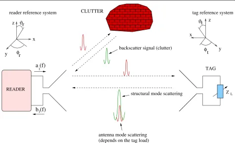
To design dedicated architectures for backscatter com-munication, it is fundamental to understand the basic electromagnetic (e.m.) mechanisms underlying the inter-action between the reader’s and tag’s antennas. As pre-viously mentioned, backscatter modulation consists of changing the antenna reflection properties according to information data [2]. In fact, when an e.m. wave encoun-ters an antenna, it is partially reflected back depending on antenna configuration. The antenna scattering mechanism is composed ofstructuralandantenna mode
through a proper variation of the antenna load character-istic without requiring a dedicated power source (back-scatter modulation).aThis property is currently adopted in traditional passive UHF RFID tags based on CW sig-nals to carry information from the tag to the reader.
As compared to the extensive investigations of UHF RFIDs (see [2,29-31]), further investigation of backscat-ter properties when operating with UWB signals, espe-cially in realistic environments, is needed [26,32,33]. For example, in [34], the effect of metallic objects located nearby the tag is addressed both via simulations and measurements.
A. UWB antenna backscattering
When a UWB pulse is transmitted and UWB antennas are employed, the reflected signal takes the form shown in Figure 1. The structural and antenna mode scattering components are plotted separately for con-venience. The antenna mode-scattered signal can be varied according to the antenna load,ZL, whereas the scattering of the structural mode remains the same. Among the various possibilities, three particular choices are of interest for passive UWB RFID: ZL = 0 (short circuit), ZL = ∞ (open circuit), and ZL=Z∗A
(matched load), where ZA is the antenna impedance. Ideally, antenna mode-scattered waveforms have a
phase difference of 180° between the case of open- and short-circuit loads, whereas no antenna mode scatter-ing exists in the case of a perfectly matched load. In UWB antennas, the structural mode component takes a significant role in the total scattered signal; in fact, it is typically 1 or 2 orders of magnitude higher than that of the antenna mode [25,32]. In addition, signals scat-tered by the surrounding environment (clutter) are inevitably present and superimposed on the useful sig-nal. In general, it is expected that the clutter and the antenna structural mode scattering have a significant impact at the reader’s antenna, thus making the detec-tion of the antenna mode-scattered signal (which car-ries data) a main issue in passive UWB RFID systems. This has not yet been widely addressed, and for this purpose, ad hoc robust backscatter modulation schemes will be designed (as illustrated in Section 3).
B. The round-trip channel transfer function
To analyze the performance of backscatter modulation schemes, a proper model for the reader-tag-reader inter-action is needed.
Consider a reference scenario as shown in Figure 1 where a couple of UWB antennas, acting as tag and reader, located at distancedare present. In the simple case of linear polarization of each antenna, the far-field
(depends on the tag load)
y
z
z
y
x
r
φ
t
ϑ
t
r
ZL READER
1
backscatter signal (clutter)
TAG CLUTTER
a (f)
b (f)
1
tag reference system reader reference system
φ
ϑ
structural mode scattering
antenna mode scattering
x
radiated from the reader and incident to the tag can be
space impedance,a1(f) is the incident wave at the read-er’s port, Θr = (θreader,jreader) is the reader orientation,
and HreaderT (f;r)is the antenna’s transfer function in
the transmitting mode of the reader [35].
The e.m. wave at the tag’s antenna is partially back-scattered according to the antenna’s scattering charac-teristics which depend on the antenna load (different load configurations will be referred to as tag statusX) and reader-tag orientation in the 3D spaceΘ= {Θr,Θt},
with Θt = (θtag, jtag) being the tag orientation. The
antenna mode component of the received backscatter signal at reader’s antenna port is given by
b1(f;d, X, ) =HreaderR (f;r)· component of the field scattered by the tag due only to the antenna mode. Therefore, we can express the tag’s transfer function as
In particular, it can be shown that the amplitude char-acteristic ofHtag(f;Θ,X) can be expressed as It turns out that this transfer function depends on the reader and local tag orientationΘ, but it is not depen-dent on the distance, since it relates the incoming plane wave complex amplitude at the tag to the far field radiated spherical wave. It is, for example, easy to prove thatHtag(f; Θ,X) = 1 for a lossless tag re-radiating iso-tropically. By considering the relationship between the transmitting and receiving modes of the reader
HRreader(f;r) =−j λ 4πH
T
reader(f;r) (5)
we finally obtain the round-trip transfer function for linear polarized antennas:
Note from (6) that, in free-space propagation condi-tions, the channel gain decreases with the distancedof an exponent factor of 2 instead of 1 as happens in con-ventional communication links.
In a UWB RFID system the reader’s antenna emits typi-cally a very short pulseg(t). We denotew(t;d, X,Θ) the backscattered signal, received back by the reader’s antenna, because of the tag’s antenna mode, shape and energy of which are a function of the tag status X (open, short, loaded) as well as ofΘ. In the frequency domain, it is
W(f;d, X, ) =G(f)H(f;d, X,). (7)
In a more realistic scenario, where several scatterers might be present, H(f; d, X, Θ) must also account for multipath components arising due to reflections. As of now, neither statistical nor deterministic models for UWB backscatter round-trip channel with multipath are present in the literature. For this reason, in the numeri-cal results, measured data collected in a realistic indoor scenario, described in the next section, will be used to assess the performance of the proposed UWB RFID system.
C. Measurement campaign set-up
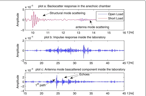
Experimental data were collected in two different narios in ENSTA-ParisTech laboratory. The first sce-nario is in a controlled environment consisting of an anechoic chamber. Data collected can be successfully utilized to characterize the UWB antenna backscatter properties and to assess the system performance in ideal conditions. The second scenario (shown in Figure 2) is a realistic indoor environment consisting of a laboratory with furniture and having dimensions 5.13 × 4.49 m2. In this case, the data collected enable the performance characterization in close-to-reality conditions.
antennas dressed with absorbers to create a quasifree-space condition. The laboratory environment consisted of a room of dimension 5.13 × 4.49 m2, where a rectangular grid of nine points as shown in Figure 2, spaced out of about 1 m in depth and 70 cm in width, was defined. The tag DFMS antenna was positioned alternatively in each point on a vertical support still dressed with absorbers. For both cases, a simple data post-processing was per-formed to obtain the antenna backscattering response from the measured parameterS21=H(f;dref,X,Θ). The collected data were first windowed in the frequency domain to avoid ringing effect. Then, applying the inverse Fourier transform, the signal in the time domain was derived. In the post-processing phase, the transmitted pulse has been chosen to obtain a transmitted signal com-pliant with the 3.1-10.6 GHz FCC mask. Specifically, the 6th derivative Gaussian monocycle has been considered [15].
Figure 3a shows the backscattered signal in the anec-hoic chamber for open- and short-load conditions. In order to easily discriminate in the time domain the struc-tural mode from the antenna mode, a 50Ωcoaxial cable
(delay line) of electric length 40 cm was inserted between the tag antenna and the load. The structural and antenna modes can be clearly distinguished, where only the latter depends on the antenna load. In particular, the difference of 180° for the antenna mode scattering between the two load conditions is clearly evidenced. It has to be remarked that the delay line used for measurements is not required in a real system implementation as the com-munication scheme proposed in this article is able to dis-criminate between the antenna and structural mode components, even if they are time overlapped, as will be illustrated in the next section.
to indirect paths between the tag and the reader. In most of the considered configurations, the normalized cross-correlation rbetween the backscattered signals in the case of open- and short-circuit loads is close to -1, as expected for antenna mode signals. This good sym-metry property is useful in case of signaling schemes employing antipodal pulses and justifies, in the following analysis, the approximation of perfect pulse symmetry, i. e.,w(t) = w(t; d, 0,Θ) = -w(t; d, 1,Θ), where for nota-tion compactness, we have hidden inw(t) the explicit dependence ondandΘ.
3. Backscatter Communication Using UWB Signals
A. System model
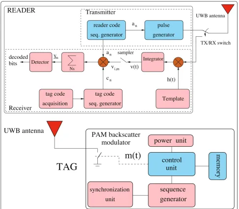
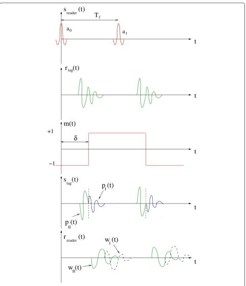
Consider a scenario where a reader interrogates Ntag
tags located in the same area. In Figure 4, the architec-tures for tag and reader are shown. The reader is com-posed of a transmitter and a receiver section both connected to the same UWB antenna through a TX/RX switch. During the interrogation phase, the reader trans-mits a sequence of UWB pulses, each having energy Et, modulated by a periodic binary sequence {an} of period
Ns, withan Î{-1, +1}, specific to that particular reader (reader’s code). Without loss of generality, an infinite interrogation sequence of pulses separated byTfseconds (frame time) is considered, that is,
sreader(t) =
∞
n=−∞
an·g(t −nTf). (8)
The frame timeTfis chosen so that all backscattered signals are received by the reader before the transmis-sion of the subsequent pulse, thus avoiding inter-frame interference. In indoor scenario, Tf = 50-100 ns is usually sufficient to this purpose [38].
During the transmission of each pulse, the antenna is connected to the transmitter section. It is then kept connected to the receiver section during the remaining time until the following pulse is transmitted. Each pulse in (8) is backscattered by all tags as well as by all the surrounding scatterers present in the environment that form the clutter component.
The main task of the receiver section of the reader is to detect the useful backscattered signal component (i.e.,
10 11 12 13 14 15 16
−5 0 5x 10
−5
t [ns]
Amplitude
plot a: Backscatter response in the anechoic chamber
15 20 25 30 35 40 45
−2 0 2x 10
−4
t [ns]
Amplitude
plot b: Impulse response inside the laboratory
15 20 25 30 35 40 45
−4 −2 0 2
x 10−6 plot c: Antenna mode bascattered component inside the laboratory
t [ns]
Amplitude
Open Load Short Load Structural mode scattering
antenna mode scattering
1st path
Echoes
Figure 3Example of backscatter responses collected inside in the anechoic chamber (plot a) at distance dref= 1.46 m, in the
the antenna mode scattering dependent on antenna load changes) from the signals backscattered by the antenna structural mode and other scatterers (clutter), which are, in general, dominant. To this purpose, a quite general backscatter modulator architecture has been proposed in [24], allowing for different signaling schemes, such as pulse amplitude modulation (PAM), pulse position mod-ulation (PPM), and ON-OFF keying. In this study, the performance of a simplified version of the tag architec-ture in [24] by considering the 2-PAM signaling is ana-lyzed. In this case, the backscatter modulator reduces to a simple switch as shown in Figure 4. The analysis can be easily extended to other signaling schemes.
The reader and the tags have their own independent clock sources and hence they have to be treated as
asynchronous. Let us denote Δ(k)= δ(k) +Tf u(k), with
u(k)integer and 0≤δ(k)< Tf, the clock offset of thekth tag with respect to the reader’s clock.
To make the uplink communication between the kth tag and the reader robust to the presence of clutter, interference, and to allow multiple access, each tag is designed to change its status (short or open circuit) at each frame time Tf according to the data to be trans-mitted and a periodic tag’s code {c(nk)}, with
c(nk)∈ {−1, +1}, of periodNs. Specifically, each tag infor-mation symbol d(k)
n ∈ {−1, +1} is associated to Ns
pulses, thus the symbol duration equals Ts =TfNs. In this way, the polarity of the reflected signal changes according to the tag’s code sequence during a symbol
Template
samplerIntegrator
h(t)
tag code
Nsdecoded
bits
n
n
Transmitter
READER
reader code
pulse
generator
seq. generator
Detector
y
mUWB antenna
TX/RX switch
Receiver
a
a
tag code
acquisition
seq. generator
c
nv
i,mv(t)
m(t)
generator
unit
PAM backscatter
UWB antenna
unit
power
control
memory
synchronization
sequence
modulator
TAG
unit
time, whereas the information symbol affects the entire sequence pulse’s polarity at each symbol. Therefore, the backscatter modulator signal, commanding the tag’s switch, can be expressed as
m(k)(t) = and zero otherwise.b
In the following analysis, the tag response due to the antenna mode is examined whereas the antenna struc-tural mode will be treated as part of the clutter, since it does not depend on data symbols. As a consequence, any clutter removal technique adopted will be also effec-tive on the antenna structural mode component.
The signal received by thekth tag is given by
rtag(k)(t) = response to g(t) which includes also the propagation delay.
According to (10) and (9), and considering perfect pulse symmetry in the two antenna load conditions, the signal scattered by the kth tag can be written as (see also the example in Figure 5)
s(tag(k)t) =rtag((k)t)·m(k)(t)
In (11), we assumed a perfect switch, i.e., a switch characterized by an instantaneous switching time as well as absence of ringing effects. These effects may not be negligible during the synchronization phase when load changes could happen in the middle of a pulse thus leading to pulse distortion. However, they do not affect the system performance once the reader has been syn-chronized to the backscattered signal. Synchronization techniques are investigated in [39] and are out of the scope of this article.
The received signal at the reader isc
rreader(t) =
where n(t) is the additive white Gaussian noise (AWGN) with two-sided power spectra density N0/2 andw(C)(t) is the backscattered version of the pulseg(t) due to the clutter component which also accounts for pulse distortion, multipath propagation, and tag’s antenna structural mode. The signalr(readerk) (t)represents the received useful component due to thekth tag, i.e.,
r(readerk) (t) = round-trip response to g(t) of the backscatter link defined in Section 2.
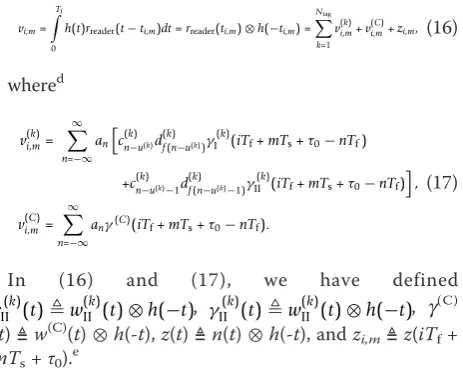
Consider the reader’s receiver scheme reported in Figure 4 where the received signal is correlated with a local waveform template h(t) with unitary energy. The output is then sampled at intervalsti,m=iTf +mTs+τ0,
In (16) and (17), we have defined
γ(k)
Without loss of generality, we consider the problem of detecting the data bit d(1)
m of tag #1 (useful tag). As shown in Figure 4, to remove the clutter component at the receiver, the sampled signal vi,mis multiplied by the composite sequence{c(1)
n ·an}, which identifies both the reader and the desired tag #1.f In particular, all the resulting Ns samples at the output of the correlator composing a data symbol are summed up to form the
s (t)
reader
(t)
a
0a
1T
fm(t)
δ
p (t)
II
w (t)
r (t)
tag+1
−1
reader
(t)
r
p (t)
II
w (t)
II
t
t
t
t
t
tag
s
thatc(i+k)mNs=ci(k), andai+mNs=ai ∀i, the decision vari-dom variable (RV) with zero mean and variance
σ2
z =NsN0/2.
The componentξm accounts for the MUI and can be expressed as follows:
whose effect on the decision variable strictly depends on the cross-correlation property between codes{c(1)i }
and{c(ik)}.
In the following, we assume that code synchronization is achieved after an initial acquisition phase, i.e.,u(1)= 0. To this purpose, powerful acquisition techniques (e.g., [40]) can be adopted. From (18), we have
ym=d(1)m
Looking at (21), it can be noted that the useful term depends on the partial autocorrelation properties of code{c(1)i }.
As a further hypothesis, we assume that a perfect TOA estimate is available. The TOA estimator robust to clutter proposed in [39] can be adopted to this purpose. Once the TOA is known, the reader can adjust its inter-nal clock so that it becomes synchronous to that of the intended tag, i.e.,δ(1)= 0, and the optimal choice for τ0
can be derived. In such a caseg
γ(1)
and (21) can be further simplified leading to
ym=d(1)m NsEw+ξm+y(mC)+zm=d(1)m ρEs+ym(C)+ξm+zm, (23)
where Es =Ns Ew, and ris the normalized cross-cor-relation between pulsesw(1)I (t)andh(t), which accounts for the mismatch due to pulse distortion. ParametersEw
andEs represent the average received energy per pulse and symbol, respectively.hFor further convenience, we define the signal-to-clutter ratio (SCR) as SCR = Es
NsEc,
Note that the accurate estimation of τ0, which is a
peculiarity of UWB signals, allows for high accuracy ranging, and hence high accuracy localization of the tag when at least three readers access the tag [12,15,41].
B. Code choice for clutter removal and multiple access Looking at (18) and (19), it can be noted that only the antenna mode-scattered signals are modulated by the combination of the tag’s and reader’s codes{c(ik)}and {ai}, whereas all the clutter signals’components (includ-ing the antenna structural mode scatter(includ-ing) are received modulated only by the reader’s code {ai}. This suggests that, as can be deduced from (19), to completely remove the clutter component, and hence the antenna structural mode component, it is sufficient that the tag’s code
{c(1)i } has zero mean, i.e., Ns−1
n=0 c (1)
n = 0, leading to
y(mC)= 0, if a quasi-stationary scenario within the symbol timeTsis assumed.
Regarding the MUI, the situation is similar to what happens in conventional code division multiple access systems where the performance is strictly related to the partial cross-correlation properties of codes{c(1)i }and
{c(ik)}[42]. Classical codes such as Gold codes or m -sequences offer good performance. Unfortunately, they are composed of an odd number of symbols, and hence there is no way to obtain a zero mean code to comple-tely remove the clutter. However, considering thatm -sequences have a quasi-balanced number of “+1” and
“-1,” i.e., their number differs no more than 1, one option to achieve clutter removal is to lengthen the code by one symbol so that the resulting code had a zero mean. As a consequence, we expect a certain degradation in terms of multiple access performance, especially when short codes are adopted. In the numeri-cal results, this aspect will be investigated.
When the scenario is quasi-synchronous, i.e., u(k)= 0
where the UWB tag is supposed to be woken up by a dedicated control signal sent in the UHF band.
C. Performance in a single-tag scenario
We now investigate the performance in a single-tag sce-nario to gain some insights about the attainable ultimate performance using the backscatter communication mechanism. The complete multi-tag scenario will be investigated in the numerical results using experimental data. In the absence of other tags in the environment, we haveξm= 0, whereas clutter contribution is comple-tely suppressed thanks to the adoption of zero mean codes.
The simplest UWB receiver is the single-path matched filter (SPMF) [44] where, in the absence of other infor-mation, h(t) can be chosen to be proportional to w(t;
dref, 0,Θmax), i.e., the received pulse at the reference
dis-tance dref in free-space propagation at the orientation Θmaxof maximum tag’s antenna radiation. This receiver
is optimal in AWGN at Θmax, but it is in general
sub-optimal in a multipath scenario. In such a case, the receiver in Figure 4 can easily be extended to obtain a Rake structure composed of a number Lp of fingers, each of them synchronized to a different path. The per-formance of the SPMF, or any other receiver solutions such as those based on Rake structures, are bounded by the ideal matched filter (IMF) receiver. The IMF recei-ver is equivalent to a Rake receirecei-ver with unlimited cor-relators (all Rake Receiver) and a perfect estimate of the received waveform to be used as local template h(t) [44,45]. This means that h(t) is proportional to the effective received waveformw(t) and, consequently, the performance of the IMF can be obtained by settingr= 1 in (23). In general, from (23), it is easy to show that the bit error probability (BEP) is given simply by
Pb=
1 2erfc
⎛ ⎝
Esρ2
N0
⎞
⎠, (24)
where erfc(·) is the complementary error function. For further convenience, we define Gref=Eref/Et, i.e., the round-trip channel power gain at the reference dis-tance dref and at the maximum direction of radiation Θmax in AWGN scenario, where Eref is the received
energy per pulse at the reference distance dref. In addi-tion, we assume a typical exponential path loss law where the power path loss exponent b usually ranges between≈1.8 and≈ 4 [38]. The BEP can be rewritten as
Pb=
1 2erfc
⎛ ⎜ ⎝
PtGrefρ2(drefd ) 2β
N0Rb
⎞ ⎟
⎠, (25)
whereRb= 1/(Ns Tf) is the data rate (symbol rate), and Pt= ETtf. It is interesting to note that the exponent
2b is present in (25) instead of b to account for the two-way link.
4. Numerical Results
In order to evaluate the performance of the proposed passive UWB RFID communication system, the follow-ing parameter values have been considered: Tf= 100 ns,
F= 4 dB (receiver noise figure), and effective radiated isotropic power (EIRP) EIRP = -6.7 dBm.
A. Range-data rate trade-off in single-tag anechoic chamber scenario
Figure 6 shows the achievable operating range as a func-tion of the data rateRbfor a fixed target BEPPb= 10-3. A SPMF receiver in anechoic chamber scenario (AWGN channel) is considered using measurement data for dif-ferent tag’s antenna orientation offsetsjwith respect to the maximum radiating angle. For each measured data-set, the normalized cross-correlation coefficientr was calculated and used in (25). For the BAV antenna,Gref
= -75 dB, which accounts also for the reader’s antenna gainGreader = 5 dB. From the figure, it can be seen that, for example, for data rateRb= 103bits/s, an operating range larger than 20 m can be achieved. However, antenna radiation pattern and pulse distortion might determine a significant performance degradation when devices are not oriented to the maximum radiating direction as can be noted in Figure 6 (see curves withj
Figure 6Tag-reader operating range in meters as a function of the data rate forPb= 10-3and different tag orientations in the
≠0). This degradation can be mitigated using, for exam-ple, multiple readers or antennas [46]. For comparison, the corresponding operating ranges in free-space condi-tions are reported for UHF-passive RFID tags operating at 868 MHz and 2.4 GHz, respectively, with a trans-mitted EIRP of 500 mW according to European regula-tions [19]. As can be noted, using the UWB technology a significantly larger operating range is achievable with respect to that of UHF-based RFID systems, especially for low data rates, with a dramatically reduced trans-mitted power level (≈0.09 vs. 500 mW). It is important to remark that the ongoing study in the European Regu-latory Framework is trying to establish that location tracking equipment, operating indoors in the reduced frequency band 6.4-8.5 GHz, could increase both the average and peak effective isotropically radiated powers by up to 10 dB (-31.3 and 10 dBm/50 MHz, respec-tively), provided their duty cycle does not exceed 2.5% [20]. This would mean 10 times increased data rate, thus making passive UWB RFID very attractive for next generation RFID systems as complementary or integrat-ing technology [27].
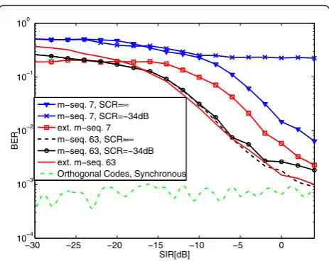
B. BER-SIR in multi-tags anechoic chamber scenario with artificial clutter
We evaluate the BER in the presence of an interfering tag as a function of the signal-to-interference ratio (SIR). The signal-to-noise ratio (SNR) has been fixed to 7 dB, corresponding to an error floor of about 10 -3in the absence of interference. Results have been obtained by Monte Carlo simulations starting from antenna back-scatter measurements in anechoic chamber. The inter-fering tag, the clutter and the thermal noise signal components have been added artificially according to the set SNR, SIR, and SCR values. The clutter waveform has been taken from measurements in the laboratory environment. The worst-case scenario with the interfer-ing signal completely overlapped to the useful one is considered.
In Figure 7, results associated to different spreading codes are compared. In the quasi-synchronous scenario, orthogonal Hadamard codes are used. As expected, the performance is not sensitive to the presence of both the interference and the clutter (because of the zero-mean code used). In the asynchronous scenario, m-sequences spreading codes of length 7 and 63 have been consid-ered. From the curve corresponding tom-seq. 7, it can be observed that when the clutter is present and it is significative (SCR = -34 dB), even for large SIR values, the performance is limited by the clutter. A remarkable improvement can be obtained by extending the length of the code by one (zero-mean code). When longer codes are used (e.g.,m-seq. 63), the impact of clutter becomes less significant and good performance can be
achieved even using quasi zero-mean codes. These con-siderations suggest that the adoption of extended m -sequences is the appropriate choice, especially when working with short codes.
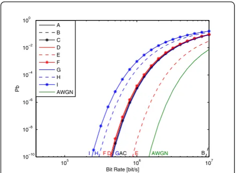
C. BEP-data rate in single-tag laboratory scenario
Results related to the SPMF and IMF receivers in every location in the grid inside the laboratory are shown in Figures 8 and 9, respectively, in terms of BEP calculated using (25) and deriving rfrom measurements. For the sake of comparison, the performance in AWGN is also reported ford= 1.46 m.
As expected, the performance of the IMF receiver is significantly better than that obtained using the simple SPMF receiver because all the useful energy coming
−30 −25 −20 −15 −10 −5 0
10−4 10−3 10−2 10−1 100
SIR[dB]
BER
m−seq. 7, SCR=∞
m−seq. 7, SCR=−34dB ext. m−seq. 7 m−seq. 63, SCR=∞
m−seq. 63, SCR=−34dB ext. m−seq. 63
Orthogonal Codes, Synchronous
Figure 7BER as a function of the SIR in the anechoic chamber scenario where clutter is summed up artificially. DFMS antenna considered.
105 106 107 10−10
10−8 10−6 10−4 10−2 100
Bit Rate [bit/s]
Pb
A B C D E F G H I AWGN
B A D E
F
C
G I H
Figure 8BEP as a function of the bit rateRbin different tag
from multipath is captured and the performance depends only on the received power. In fact, the SPMF receiver is not able to collect the energy from multipath and suffers from pulse distortion due to propagation as well as antenna effects. This problem can be mitigated by considering more complex receiver structures such as those based on Rake solutions performance of which is bounded by the one provided by the IMF receiver. The performance obtained with the tag located at loca-tionB is better than that in AWGN condition because of the shorter distance (1.10 vs. 1.46 m). Note that in some cases tags placed at larger distances provide a bet-ter performance. This depends on the higher amount of energy that can be collected in some locations because of the presence of richer multipath components in the received signal.
As a numerical example, with a target BEPPb= 10-3, data rates up to 200 kbit/s at a distance of 3.10 m with a transmitted power lower than 1 mW are feasible in a realistic environment.
D. BER-SNR in multi-tag laboratory scenario
In Figure 10, the bit error rate (BER) as a function of the SNR whenNtag= 6 tags are present is reported. The signal measured from the location D of the grid is considered as the signal backscattered by the useful tag, and then we associate the backscattered signals coming from locations A, B, C, E, and F (see the map in Figure 2) to the interfer-ing signals. Different SNR values have been obtained by adding the correspondent artificial thermal noise.
It is possible to see the performance gain obtained when the extendedm-sequence 63 is adopted. This indi-cates that the effect of the clutter is dominant with respect to the effect of the MUI. A similar conclusion
can be drawn when only one interfering tag located in F is present and an extendedm-sequence 7 is considered.
5. Conclusions
UWB technology in next generation RFID systems is a promising solution to overcome most of the limitations of current narrow bandwidth RFID technology. In this article, we have addressed UWB RFID systems adopting backscatter modulation by proposing a reader-and-tag architecture capable of working in the presence of strong clutter and interference. The achievable range and performance has been investigated using measured data collected in controlled and realistic environments. It has been shown that clutter is the main limiting fac-tor and that it can be mitigated or suppressed through the architecture proposed in this article and the adop-tion of zero mean spreading codes without compromis-ing the performance in multi-tag scenario. Numerical results show that operating ranges of several meters are feasible in realistic scenarios with a transmitted power less than 1 mW.
6. Competing interests
The authors declare that they have no competing interests.
Endnotes a
The structural mode-scattered component here is con-ventionally defined as the signal scattered when the antenna load is matched. In the literature, it is often defined with respect to the short-circuit load [28]. In
105 106 107 10−10
10−8 10−6 10−4 10−2 100
Bit Rate [bit/s]
Pb
A B C D E F G H I AWGN
B
FD GAC E
H
I AWGN
Figure 9BEP as a function of the bit rateRbin different tag
locations (Laboratory scenario). The IMF receiver is considered.
0 2 4 6 8 10
10í4 10í3 10í2 10í1 100
SNR [dB]
BER
míseq. 7, N tag=2 ext míseq.7, Ntag=2 míseq. 63, Ntag=6 ext míseq. 63, Ntag=6
any case, whatever convention is adopted, the following analysis and the results are not affected. bOperator⌈x⌉
denotes the smallest integer larger than or equal tox.
c
Coupling effects between close tags are not considered here. They deserve future investigations, even though we expect that, in most cases, their impact on system performance is negligible thanks to the different spread-ing codes adopted in each tag.d⊗denotes the convolu-tion operator. eAccording to the design criteria for Tf
illustrated before, the support ofg(t) belongs to [0, Tf], and no inter-frame interference is present. fMultiple readers may access the same tag by using different reader codes provided that they are designed with good cross-correlation properties.gNote that under perfect-timing condition, it isw(1)I (t) =w(1)(t)and w(1)
II (t) = 0.
Moreover, as already mentioned, any non ideal switch-ing effect becomes negligible because it affects parts of the received signal not interested by the useful backscat-tered pulse. hNote that the energy of the useful tag response may vary for different delays and codes when the reader is not synchronized. In such a case, (22) does not hold anymore.
Acknowledgements
The authors would like to thank Raffaele D’Errico for his assistance on measurement equipment and Nicolò Decarli for his useful suggestions. This study has been performed within the framework FP7 European Project SELECT (Grant no. 257544).
Author details 1
WiLAB, Dipartimento di Elettronica, Informatica e Sistemistica (DEIS), University of Bologna at Cesena, Via Venezia 52, Cesena (FC) 47521, Italy
2ENSTA-ParisTech 32 Boulevard Victor, Paris Cedex 15 75739, France
Received: 30 August 2010 Accepted: 28 July 2011 Published: 28 July 2011
References
1. K Finkenzeller,RFID Handbook: Fundamentals and Applications in Contactless Smart Cards and Identification, 2nd edn. (Wiley, 2004)
2. V Chawla, DS Ha, An overview of passive RFID. IEEE Appl Pract.45, 11–17 (2007)
3. European Commission DG Information Society and Media/Unit G2
“Microsystems”. To strengthen european technology: the support of RFID within FP7 (September 2007)
4. EPCGlobal, Class 1 generation 2 UHF air interface protocol standard v.1.0.9 (2005)
5. E Ngai, KK Moon, FJ Riggins, CY Yi, RFID research: an academic literature review (1995-2005) and future research directions. Int J Prod Econ.112(2), 510–520 (2008). special Section on RFID: Technology, Applications, and Impact on Business Operations. doi:10.1016/j.ijpe.2007.05.004 6. R Verdone, D Dardari, G Mazzini, A Conti,Wireless Sensor and Actuator
Networks: Technologies, Analysis and Design, (Elsevier Ltd, London, 2008) 7. D Kim, M Ingram, WJ Smith, Measurements of small-scale fading and path
loss for long range RF tags. IEEE Trans Antennas Propag51(8), 1740–1749 (2003). doi:10.1109/TAP.2003.814752
8. D Ha, P Schaumont, Replacing cryptography with ultra wideband (UWB) modulation in secure RFID, in2007 IEEE International Conference on RFID, Grapevine, TX, USA (March 2007)
9. C Mutti, C Floerkemeier, inCDMA-based RFID systems in dense scenarios: concepts and challenges, Las Vegas, USA 215–222 (April 2008)
10. T van Deursen, S Radomirović, Security of RFID protocols–a case study. Electron Notes Theor Comput Sci.244, 41–52 (2009)
11. J Griffin, G Durgin, Reduced fading for RFID tags with multiple antennas, in
Antennas and Propagation International Symposium, 2007 IEEE, pp.
1201–1204 (June 2007)
12. D Dardari, R D’Errico, C Roblin, A Sibille, MZ Win, Ultrawide bandwidth RFID: the next generation? Proc IEEE.98(9), 1570–1582 (2010) (Special Issue on RFID–A Unique Radio Innovation for the 21st Century)
13. MZ Win, RA Scholtz, Impulse radio: how it works. IEEE Commun Lett.2(2), 36–38 (1998). doi:10.1109/4234.660796
14. MZ Win, D Dardari, AF Molisch, W Wiesbeck, J Zhang, History and Applications of UWB. Proc IEEE.97(2), 198–204 (2009) (Special Issue on Ultra-Wide Bandwidth (UWB) Technology & Emerging Applications) 15. D Dardari, A Conti, U Ferner, A Giorgetti, MZ Win, Ranging with ultrawide
bandwidth signals in multipath environments. Proc IEEE.97(2), 404–426 (2009) (Special Issue on UWB Technology & Emerging Applications) 16. A Giorgetti, M Chiani, MZ Win, The effect of narrowband interference on
wideband wireless communication systems. IEEE Trans Commun.53(12), 2139–2149 (2005). doi:10.1109/TCOMM.2005.860047
17. RJ Fontana, SJ Gunderson, Ultra-wideband precision asset location system,
inProc of IEEE Conf on Ultra Wideband Systems and Technologies (UWBST).
21(1), 147–150 (May 2002)
18. D Dardari, Pseudo-random active UWB reflectors for accurate ranging. IEEE Commun Lett.8(10), 608–610 (2004). doi:10.1109/LCOMM.2004.836838 19. GD Vita, G Iannaccone, Design criteria for the RF section of UHF and
microwave passive RFID transponders. IEEE Trans Microwave Theory Tech.
59(9), 2978–2990 (2005)
20. W Hirt, The european UWB radio regulatory and standards framework: overview and implications, inIEEE International Conference on
Ultra-Wideband, ICUWB 2007, Singapore, Singapore 733–738 (2007)
21. JA Paradiso, T Starner, Energy scavenging for mobile and wireless electronics. IEEE Pervas Comput.4, 18–26 (2005)
22. Z Zou, M Baghaei-Nejad, H Tenhunen, L-R Zheng, An efficient passive RFID system for ubiquitous identification and sensing using impulse UWB radio, ine & i Elektrotechnik und Informationstechnik, Springer Wien.124(11), 397–403 (November 2007). doi:10.1007/s00502-007-0483-y
23. J Reunamaki, Ultra wideband radio frequency identification techniques. U.S. Patent 7,154,396, 26 Dec 2006
24. D Dardari, Method and apparatus for communication in ultra-wide bandwidth RFID systems. International Patent Application PCT/IB2009/000 360, (Feb. 25, 2009)
25. D Dardari, R D’Errico, Passive ultrawide bandwidth RFID. inIEEE Global
Communications Conference (GLOBECOM 2008), New Orelans, LA, USA
(November 2008)
26. F Guidi, D Dardari, C Roblin, A Sibille, inBackscatter communication using ultrawide bandwidth signals for RFID applications, ed. by Giusto D, et al The Internet of Things: 20th Tyrrhenian Workshop on Digital Communications, Pula, Sardinia, Italy (Springer-Science+BusinessMedia, 2009), pp. 251–262 27. SELECT (Smart and Efficient Location, identification, and Cooperation
Techniques) inFP7 European SELECT Projecthttp://www.selectwireless.eu 28. RC Hansen, Relationship between antennas as scatters and as radiators.
Proc IEEE.77(5), 659–662 (1989). doi:10.1109/5.32056
29. K Penttila, M Keskilammi, L Sydanheimo, M Kivikoski, Radar cross-section analysis for passive RFID systems, inIEE Proc Microwave and Antennas Propagation.153(1), 103–109 (February 2006). doi:10.1049/ip-map:20045183 30. D Kim, M Ingram, W Smith, Small-scale fading for an indoor wireless
channel with modulated backscatter, inVehicular Technology Conference, 2001. VTC 2001 Fall. IEEE VTS 54th.3, 1616–1620 (2001)
31. J Griffin, G Durgin, Link envelope correlation in the backscatter channel. Commun Lett IEEE.11(9), 735–737 (2007)
32. S Hu, CL Law, Z Shen, L Zhu, W Zhang, W Dou, Backscattering cross section of ultrawideband antennas. IEEE Anten Wirel Propagat Lett.6, 70–72 (2007) 33. S Hu, Y Zhou, CL Law, W Dou, Study of a uniplanar monopole antenna for passive chipless UWB-RFID localization system. IEEE Trans Anten Propagat.
58(2), 271–278 (2010)
34. F Guidi, A Sibille, D Dardari, C Roblin, UWB RFID backscattered energy in the presence of nearby metallic reflectors, inEuropean Conference on
Antennas and Propagation 2011, Rome, Italy (April 2011)
36. S Bories, H Ghannoum, C Roblin, Robust planar stripline monopole for UWB terminal applications, in2005 IEEE International Conference on Ultra-Wideband, pp. 80–84 (2005)
37. J Langley, P Hall, P Newham, Balanced antipodal Vivaldi antenna for wide bandwidth phased arrays, inIEE Proc on Microwave and Antennas Propagation.143(2), (April 1996)
38. A Molisch, K Balakrishnan, D Cassioli, C-C Chong, S Emami, A Fort, J Karedal, J Kunisch, H Schantz, U Schuster, K Siwiak, IEEE 802.15.4a channel model. Final report, 2005.
39. C Xu, CL Law, TOA estimator for UWB backscattering RFID system with clutter suppression capability. EURASIP J Wirel Commun Netw.2010, Article ID 753129, 1–14 (2010)
40. W Suwansantisuk, MZ Win, Multipath aided rapid acquisition: optimal search strategies. IEEE Trans Inf Theory.52(1), 174–193 (2007) 41. D Dardari, E Falletti, M Luise,Satellite and Terrestrial RadioPositioning
Techniques–A Signal Processing Perspective(Elsevier Ltd., London, 2011) 42. M Pursley, D Sarwate, W Stark, Error probability for direct-sequence
spread-spectrum multiple-access communications. Part I: upper and lower bounds. IEEE Trans Commun.30(5), 975–984 (1982). doi:10.1109/TCOM.1982.1095553 43. M Saito, H Yamamoto, Sequence assignment of Walsh-Hadamard
sequences for quasi-synchronous multi-code CDMA systems, inThe 5th International Symposium on Wireless Personal Multimedia Communications, 2002, vol. 2. (Honolulu, Hawaii, USA, October 2002), pp. 673–677 44. MZ Win, RA Scholtz, Characterization of ultra-wide bandwidth wireless
indoor communications channel: a communication theoretic view. IEEE J Sel Areas Commun.20(9), 1613–1627 (2002). doi:10.1109/JSAC.2002.805031 45. RK Mallik, MZ Win, Analysis of hybrid selection/maximal-ratio combining in correlated Nakagami fading. IEEE Trans Commun.50(8), 1372–1383 (2002). doi:10.1109/TCOMM.2002.801495
46. R D’Errico, A Sibille, A Giorgetti, M Chiani, Antenna diversity in UWB indoor channel, inIEEE International Conference on Ultra-Wideband, 2008 (ICUWB 2008).2, 13–16 (September 2008)
doi:10.1186/1687-1499-2011-47
Cite this article as:Dardariet al.:Ultra-wide bandwidth backscatter modulation: processing schemes and performance.EURASIP Journal on Wireless Communications and Networking20112011:47.
Submit your manuscript to a
journal and benefi t from:
7Convenient online submission 7Rigorous peer review
7Immediate publication on acceptance 7Open access: articles freely available online 7High visibility within the fi eld
7Retaining the copyright to your article