LETTER Earth Planets Space,61, 1111–1115, 2009
Characteristics of deformation structure around the 2007 Niigata-ken
Chuetsu-oki earthquake detected by multi-channel
seismic reflection imaging
Tetsuo No1, Narumi Takahashi1, Shuichi Kodaira1, Koichiro Obana1, and Yoshiyuki Kaneda2
1Lithosphere Structure Imaging Research Team, Institute for Research on Earth Evolution,
Japan Agency for Marine-Earth Science and Technology, 3173-25, Showa-machi, Kanazawa-ku, Yokohama-city, Kanagawa 236-0001, Japan
2Earthquake and Tsunami research project for Disaster Prevention, Japan Agency for Marine-Earth Science and Technology,
2-15 Natsushima-cho, Yokosuka-city, Kanagawa 237-0061, Japan
(Received October 9, 2008; Revised May 24, 2009; Accepted June 2, 2009; Online published November 10, 2009)
A multi-channel seismic reflection (MCS) survey was conducted to investigate the tectonic structure off Niigata, which caused the 2007 Niigata-ken Chuetsu-oki earthquake, using the research vessel (R/V) KAIREI of the Japan Agency for Marine-Earth Science and Technology. Based on the results of data processing and interpretation of available data, three areas are identified according to seismic characteristics. The most deformed area is located on the continental shelf near the source region of the 2007 Niigata-ken Chuetsu-oki earthquake, i.e., the area east of the Yoneyama-Ogi Uplifts. A remarkable growth of folds, including fault-related folds, and a strong reflector dipping east is identifiable by localized strain concentrations. The second area is located between the Yoneyama-Ogi Uplifts and the Jouetsu Knoll in the Toyama Trough. Although the deformation of deposits in the second area was smaller than in the first area, folds are identified. The third area is located toward the west of the Jouetsu Knoll in the Toyama Trough. No significant deformed structures developed in this area. Based on the interpretation of stratigraphy obtained in previous studies, seismic characteristics, and well data, the development of an anticline was initiated by a compression field after about 3.6 Ma. In particular, the deformation of sedimentary layers by the compression field occurred rapidly after about 1.3 Ma. Folds have grown larger toward the east after about 1.3 Ma. In addition, subsidence of about 0.2 s in sedimentary layers can be seen at the western margin of the Yoneyama-Ogi Uplifts, suggesting that tectonic movement related to reverse faulting has advanced there very recently. From aftershock distribution on a depth section on line S-2 near the hypocentral region, most hypocenters were determined to be below the strong reflector. This result suggests that fold growth has accompanied past large earthquakes, such as the 2007 Niigata-ken Chuetsu-oki earthquake. Key words:2007 Niigata-ken Chuetsu-oki earthquake, multi-channel seismic reflection, deformation structure.
1.
Introduction
On July 16, 2007, the 2007 Niigata-ken Chuetsu-oki earthquake with MJ (JMA magnitude) 6.8 occurred off
Niigata, Japan (The Headquarters for Earthquake Research Promotion, 2007). Earthquakes have occurred earlier along the eastern margin and caused great damage, these include the 1964 Niigata earthquake (MJ7.5, (a) in Fig. 1), 1983
Nihonkai-Chubu earthquake (MJ7.7, (b) in Fig. 1), 1993
Hokkaido-Nansei-Oki earthquake (MJ7.8, (c) in Fig. 1),
and 2004 Mid-Niigata Prefecture earthquake (MJ6.8, (d)
in Fig. 1) (The Headquarters for Earthquake Research Promotion, 2007). Furthermore, Sagiya (2004) proposed that a large strain concentration, identified along the east-ern margin of the Japan Sea coast and in the Niigata-Kobe Tectonic Zone (NKTZ) using continuous GPS observation, has produced repeated large historical earthquakes and de-veloped an active fault belt. The 2007 Niigata-ken Chuetsu-oki earthquake, which was located in the NKTZ, was one
Copyright cThe Society of Geomagnetism and Earth, Planetary and Space Sci-ences (SGEPSS); The Seismological Society of Japan; The Volcanological Society of Japan; The Geodetic Society of Japan; The Japanese Society for Planetary Sci-ences; TERRAPUB.
such earthquake.
In this paper, we describe the structural characteristics of the deformed zone around the 2007 Niigata-ken Chuetsu-oki earthquake based on seismic reflection imaging, an in-terpretation of existing information, and a comparison with the aftershock distribution.
2.
Data Acquisition and Processing
In August 2007, we conducted a multi-channel seis-mic reflection (MCS) survey around the 2007 Niigata-ken Chuetsu-oki earthquake using the R/V KAIREI of the Japan Agency for Marine-Earth Science and Technology. MCS data were acquired along three lines (Lines l, 2, and S-3) with a total length of approximately 190 km (Fig. 1). Survey lines could not directly cover the source region and made many turns to avoid the many fishing operations present in the survey area. These lines crossed the margins of the NKTZ and the contraction deformation zones around the eastern margin of the Japan Sea (Okamuraet al., 2007). We shot an airgun array with a spacing of 50 m. This array has a total capacity of 12,000 cubic inches (about 200 liters; eight airguns with a capacity of 1,500 cubic inches each).
Fig. 1. (Left) Bathymetry and location maps of the study area. Red lines are the MCS lines of this study. YU: Yoneyama-Ogi Uplifts; JK: Joetsu Knoll; SB: Sado Basin; TC: Toyama Deep Sea Channel. Yellow star indicates the main shock of the 2007 Niigata-ken Chuetsu-oki earthquake. Blue circles indicate aftershock distribution based on Ocean bottom seismograph (OBS) observation (Shinoharaet al., 2008). Gray lines are the MCS lines of Japan National Oil Corporation (Japan National Oil Corporation, 2002) used for interpretation in this study. Crosses show the positions of Ministry of International Trade and Industry (MITI) wells. (Right) Seismicity map of events withMJ≥3 obtained from JMA seismological data (1923–2007,
0–50 km (depth), Japan Meteorological Agency, 2008), (a) aftershock region of the 1964 Niigata earthquake (MJ7.5), (b) aftershock region of the
1983 Nihonkai-Chubu earthquake (MJ7.7), (c) aftershock region of the 1993 Hokkaido-Nansei-Oki earthquake (MJ7.8), (d) aftershock region of the
2004 Mid-Niigata Prefecture earthquake (MJ6.8), and (e) aftershock region of the 2007 Niigata-ken Chuetsu-oki earthquake (MJ6.8). Broken black
circle shows the Niigata-Kobe Tectonic Zone (NKTZ) (Sagiya, 2004). Dotted area shows the contraction deformation zones based on geological studies around the eastern margin of the Japan Sea (Okamuraet al., 2007). Broken blue circle is the Niigata-Shinetsu Basin (Takano, 2002).
The standard air pressure was 2,000 psi (about 14 MPa). During the shooting, we towed a 204-channel hydrophone streamer cable with a 5200-m maximum offset, and the group interval was 25 m. The towing depth of the streamer cable was maintained at 15 m below the sea surface using depth controllers. The sampling rate was 4 ms, and the recording length was 13.5 s.
For data processing, we applied format conversion, trace header edit, trace edit, common midpoint (CMP) binning with an interval of 12.5 m, a bandpass filter (3–125 Hz), datum correction, amplitude compensation by T**2 (T is two-way travel time), an F-K filter, minimum phase con-version processing, predictive deconvolution, dip moveout processing, a radon filter for multiple suppression, velocity analysis with an interval of 1.25 km (100 CMPs), normal moveout correction, mute, a CMP stack, F-X deconvolu-tion, a bandpass filter (4–50 Hz), poststack Kirchhoff time migration, automatic gain control, and depth conversion.
3.
Interpretation and Discussion
Figure 2 shows the time-migrated seismic and depth sec-tions obtained in this study. We divided the study region into three areas according to seismic characteristics identi-fied in these sections.
The first area (red arrows in Fig. 2) is located on the con-tinental shelf near the source region of the 2007
Niigata-ken Chuetsu-oki earthquake (CMP 1–1500 on Line S-l, CMP 7000–8000 on Line S-2, CMP 1800–2800 on Line S-3 in Fig. 2), which is the region toward the east of the Yoneyama-Ogi Uplifts. Deformation in deposits was the largest in this area. Asymmetrical folds and fault-related folds were formed in the deposits, and anticlines near the source region were present in CMP 7100, 7350, and 7900 (green arrows in Fig. 3). Reflectors between anticlines were broken, and parts of the synclines were lost (CMP 7250, 7700; purple arrows in Fig. 3). In contrast, a strong reflec-tor dipping east below these folds, which were located from CMP 7000 to 8000, was identified lower than about 3.5–5 s (orange arrows in Figs. 2 and 3).
Vari-T. NOet al.: DEFORMATION STRUCTURE AROUND THE 2007 NIIGATA-KEN CHUETSU-OKI EARTHQUAKE 1113
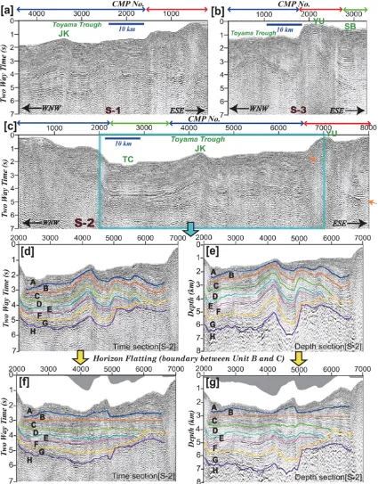
Fig. 2. (a) Time-migrated seismic sections and the interpreted section of line S-l. Red arrows show areas with the largest shortening deformation in this survey area. Blue arrows indicate areas where folds were identified, although the amount of shortening deformation in the second area was smaller than in the red-arrow areas. Green arrows show areas with no significant deformed structures, (b) time-migrated seismic sections and the interpreted section of line S-3. Orange arrows show strong reflectors dipping east below the folds, (c) time-migrated seismic sections and the interpreted section of line S-2. (d) Time section indicates interpretation of line S-2 based on previous studies of stratigraphy, seismic characteristics, and well data (Japan National Oil Corporation, 2002; Muramotoet al., 2007). (e) Depth section indicates interpretation of line S-2. (f) Interpreted time section by flattening the boundary between Units B and C along line S-2. (g) Interpreted depth section by flattening the boundary between Units B and C along line S-2.
ation in the thickness of Unit G with an unconformity is larger than those of Units C–F, which are composed of sim-ilar folds. Variation in the thickness of Units A and B is larger than that of the lower units, and that of Unit A is particularly remarkable. Approximate ages estimated by
Fig. 3. Comparison of aftershock distribution by OBS observation (Shinoharaet al., 2008) and depth section in line S-2 of the hypocentral region of the 2007 Niigata-ken Chuetsu-oki earthquake. Thick black rectangles in the lower location map show depth section area. Blue circles indicate aftershock distribution by OBS observation (Shinoharaet al., 2008). The yellow star indicates the epicenter of the main shock of the 2007 Niigata-ken Chuetsu-oki earthquake. Green arrows in the top figure show anticlines. Purple arrows show discontinuous synclines. The orange arrow shows strong reflector dipping eastward below the folds.
Formation (13–8.5 Ma); G: the Nanatani Formation (15– 13 Ma); H: the Green-tuff Formation and acoustic basement (before 15 Ma). Tectonic history regarding these ages is dis-cussed later in this section.
The third area (green arrows in Fig. 2) is located in the western part of the Toyama Trough (CMP 2400–3800 on Line S-2, CMP 1800–2800 on Line S-3 in Fig. 2). Vari-ation in the thickness of Units A–G was less than that in other areas. In addition, no significant deformed structures developed in the third area. Reflectors of erosional uncon-formity along the Toyama deep sea channel were found at travel times of approximately 0.2–1.0 s in the western part of the Toyama Trough.
The amount of deformation identified in deposits in-creased toward the east. To enable an assessment of this growth, we performed horizon flattening analysis to detect thickness variations in each layer. Figure 2 shows an exam-ple of the flattening of the boundary between Units B and C along Line S-2. The total thickness of Units A and B at the western foot of the Yoneyama-Ogi Uplifts is greater than that of the other regions within the Toyama Trough, sug-gesting that folds began to develop after the formation ages of Unit C. Similar characteristics of the fold can be seen not only at the western foot of the Yoneyama-Ogi Uplifts but also at the eastern margin of the Joetsu Knoll. In ad-dition, subsidence of sedimentary layers of approximately 0.2 s can be seen at the western foot of the Yoneyama-Ogi uplifts, suggesting that very recent tectonic movement re-lated to a reverse fault dipping eastward has advanced there. Variation in the thickness of Unit A is much greater than that of Unit B. Our results suggest that the deformation started after the formation ages of Unit C and that the de-velopment of the fold was accelerated after the formation of Unit B. Based on a comparison of the tectonic history of
the tectonostratigraphic units in the Niigata-Shinetsu basin on the land next to the basin (Takano, 2002) with the seis-mic interpretation in this study, Units B–C correspond to the tectonic inversion and incipient compression stage (6.5– 1 Ma). In this stage, tectonic subsidence, which had oc-curred up to 6.5 Ma, stopped, and the accumulation rate in-creased again. In addition, the sedimentation configuration of this stage was strongly affected by syndepositional fold-ing due to the compressional stress field. Local variation in the thickness of Units B–C suggests an effect on syn-depositional folding due to the compressional stress field. Moreover, Unit A corresponds to the intense compression stage (1 Ma–present; Takano, 2002). The more intense compressional stress gave rise to a higher supply rate of coarse elastics and more prominent syndepositional fold-ing within the basin (Takano, 2002). Extremely remarkable spatial variation in the thickness in Unit A, which is accom-panied with the growth of folds, suggests intense compres-sion after 1 Ma.
We also suggest that the remarkable growth of the folds with localized strain concentration in the first area is stronger than that in the second area. Okamura (2003) sug-gested that fault-related folds and an imbricate thrust sys-tem were formed off Naoetsu. He also argued that the thrust system has developed by the stepwise growth of new thrust faults in front of the previously active thrust, which indi-cates that active deformation and seismogenic zones have migrated to the northwest as each new thrust has formed. Moreover, similar deformed structures, such as fault-related folds, have been identified near the source region.
T. NOet al.: DEFORMATION STRUCTURE AROUND THE 2007 NIIGATA-KEN CHUETSU-OKI EARTHQUAKE 1115
the 2007 Niigata-ken Chuetsu-oki earthquake revealed that most hypocenters were below the strong reflectors (orange arrows in Fig. 3). Furthermore, aftershocks dipping east were distributed eastward to the asymmetrical anticline in CMP 7900 (green arrows in Fig. 3). As a result, we suggest that past large earthquakes brought about tectonic stress in the deposits and that such stress caused the development of structures such as fault-related folds in the study area. To conduct a detailed study of the source fault of this earth-quake, we need to acquire seismic reflection data across the source region. In addition, compared with the tectonic map around the eastern margin of the Japan Sea (dotted area in Fig. 1) of Okamuraet al.(2007), deformed structures of the first area (red arrows in Fig. 2) and the second area (blue ar-rows in Fig. 2) identified in this study indicate contraction deformation zones.
4.
Conclusion
We examined the deformation structure in deposits and basements near the source region of the 2007 Niigata-ken Chuetsu-oki earthquake by seismic reflection imaging and interpretations based on available studies of stratigraphy, seismic characteristics, and well data. The growth of the folds was initiated by a compression field after the forma-tion age of Unit C (after about 3.6 Ma). In particular, the deformation of sedimentary layers by the compression field has accelerated since the formation age of Unit B (after about 1.3 Ma). The growth of folds after about 1.3 Ma has been stronger in the eastern Toyama Trough area east of the Yoneyama-Ogi Uplifts than, in particular, at the western foot of the western Toyama Trough. Based on a comparison of the tectonic history of the tectonostratigraphic units in the Niigata-Shinetsu by Takano (2002) with the seismic inter-pretation in this study, Units B–C correspond to the tectonic inversion and incipient compression stage (6.5–1 Ma), and Unit A was formed during the intense compression stage (1 Ma–present). The very remarkable spatial variation in the thickness of Unit A, accompanied with the growth of folds, is thought to have been caused by intense compres-sion after 1 Ma. A comparison of aftershock distribution by OBS observation (Shinoharaet al., 2008) and a depth sec-tion of Line S-2 of the hypocentral region shows that most hypocenters were distributed below strong reflectors dip-ping east, suggesting that such past large earthquakes have brought about deformation in the deposits, such as fault-related folds.
Acknowledgments. This survey is supported by the Special Co-ordination Funds (MEXT, Japan), “Urgent study on the 2007 Niigata-ken Chuetsu-oki earthquake.” We are grateful to the ma-rine technician team and crews of Nippon Mama-rine Enterprises Ltd. for their efforts in obtaining MCS data. We thank editor Takashi Iidaka and anonymous reviewers for giving us valuable advice and suggestions for improving the manuscript. We also thank Kaoru Takizawa, Toshihiro Ike, Takeshi Nakamura, Seiichi Muira, Takeshi Sato, and Mikiya Yamashita for their support and sug-gestions. Aftershock hypocenter data for the 2007 Niigata-ken Chuetsu-oki earthquake were provided by Shinoharaet al.(2008). We used “The Generic Mapping Tools” (Wessel and Smith, 1991) and “JTOPO30” bathymetry data from Japan Hydrographic Asso-ciation to produce the illustrations.
References
Japan Meteorological Agency,The Annual Seismological Bulletin of Japan for 2007 (DVD-ROM), Japan Meteorological Agency, Tokyo, 2008. Japan National Oil Corporation,Report on basic exploration in
Sadoki-nansei, 48 pp, Japan National Oil Corporation, Tokyo, 2002 (in Japanese).
Muramoto, K., M. Osawa, M. Kida, and H. Arisaka, A petroleum system in the deep water of the Sado Nanseioki area in the Japan Sea based on the results of the MITI “Sadooki Nanai” Seismic Survey and the METI “Sado Nanseioki” Wells,J. Jpn. Assoc. Petroleum Technol.,72, 618– 627, 2007 (in Japanese with English abstract).
Okamura, Y., Fault-related folds and an imbricate thrust system on the northwestern margin of the northern Fossa Magna region, central Japan, The Island Arc,12, 61–73, 2003.
Okamura, Y., T. Ishiyama, and Y. Yanagisawa, Fault-related folds above the source fault of the 2004 mid-Niigata Prefecture earthquake, in a fold-and-thrust belt caused by basin inversion along the eastern margin of the Japan Sea,J. Geophys. Res.,112, doi:10.1029/2006JB004320, 2007. Sagiya, T., A decade of GEONET: 1994–2003—The continuous GPS
ob-servation in Japan and its impact on earthquake studies—,Earth Planets Space,56, xxix–xli, 2004.
Shinohara, M., T. Kanazawa, T. Yamada, K. Nahigashi, S. Sakai, R. Hino, Y. Murai, A. Yamazaki, K. Obana, Y. Ito, K. Iwakiri, R. Miura, Y. Machida, K. Mochizuki, K. Uehira, M. Tahara, A. Kuwano, S. Amamiya, S. Kodaira, T. Takanami, Y. Kaneda, and T. Iwasaki, Precise aftershock distribution of the 2007 Chuetsu-oki Earthquake obtained by using an ocean bottom seismometer network,Earth Planets Space,60, 1121–1126, 2008.
Takano, O., Changes in depositional systems and sequences in response to basin evolution in a rifted and inverted basin: an example from the Neogene Niigata-Shinfetsu basin, Northern Fossa Magna, central Japan, Sediment. Geol.,152, 79–92, 2002.
The Headquarters for Earthquake Research Promotion, The Niigataken Chuetsu-oki Earthquake in 2007, Online. 11 Janury 2008, http://www. jishin.go.jp/main/chousa/08jan chuetsu oki/index-e.htm.
Wessel, P. and W. H. F. Smith, Free software helps map and display data, Eos Trans. AGU,72, 441, 1991.