Division III
NUMERICAL SIMULATIONS OF ELASTO-PLASTIC PIPE WHIP
PHENOMENA WITH FULLY COUPLED FLUID-STRUCTURE
INTERACTION MODELS
Damijan Markovic1, Hadhemi Guefrej2
1
Structural Engineer, Basic Design Department, EDF SEPTEN, France 2 Internship Student, Basic Design Department, EDF SEPTEN, France
ABSTRACT
The High Energy Line Breaks (HELB) analyses are part of the internal hazard safety assessment of a nuclear installation. They are initiated by a sudden rupture of a piping containing liquids or gazes under high pressure or at high temperature. Various types of consequences of a pipe break need to be considered such as: flooding, pressurization, jet impingement, missile generation, pipe internal load effects and pipe whip. This communication focuses on the analysis of a pipe whip, which could, by mechanical impact, cause damage to the systems, structures and components (SSC) in the same compartment, eventually leading to a failure of additional safety functions and therefore significantly penalizing an accident scenario.
In the common safety engineering practice, the consequences of a pipe whip are assessed with a series of analytical models in order to determine the hydraulic loading, the plastic hinge location and the kinetic energy of a whipping pipe. With these conventional methods the physical phenomena have to be simplified considerably, so that they introduce a very high level of conservatisms.
The main objective of the communication is to estimate the conservatism of the conventional methods by comparison to the simulations using the state-of-the-art numerical tools, based on the non-linear fast transient finite element method with the fully coupled fluid-structure interaction between the compressible (one or two phase) fluid and the piping structure submitted to large deformations.
INTRODUCTION
A pipe whip is a possible consequence of a postulated High Energy Line Break (HELB), which can occur after a sudden rupture of a pipeline under certain thermodynamic, structural and geometrical conditions. In the common practice of HELB analyses, a pipe rupture is considered as almost instantaneous and most often circumferential. This hypotheses are improbable, but are convenient because they are very conservative and do not require a detailed understanding of all the complex physical phenomena involved.
For a given jet reaction force, a large deformation pipe whip can be modelled following the method proposed in Roemer and East (1980), based on a conservative and completely analytical approach. Their work addresses two aspects: the initiation of the pipe whip through the formation of a plastic hinge and the crushing of the whipped pipe at an obstacle.
In Micheli and Zanaboni (2003), the simplified approach of Roemer and East (1980) is compared to a time-history structural dynamic simulations using beam finite elements. From the comparison, based on several realistic HELB configurations, the authors conclude that the simplified approach is strictly conservative and that it exhibits significant margins with respect to a direct numerical time-history simulations. It is important to note that in Micheli and Zanaboni (2003), the numerical approach is applied only to the structural response, whereas the hydraulic description is simplified following the formulas from the ANSI/ANS 58-2 standard. In particular, it is assumed that the hydraulic loading grows instantaneously to its maximum steady value, a hypothesis which maximizes the dynamic load factor (DLF) of the structural response.
Going a step further with the respect to the existing work, the objective of the present communication is to present a fully coupled fluid-structure interaction (FSI) approach to simulate a pipe whip initiated by a HELB. Regarding the modelling of the structural behaviour, our approach is equivalent to the one used in Micheli and Zanaboni (2003), the main difference is being in the description of the hydraulic loading.
Whereas in the previous work, the authors use a simplified analytical model, we propose here to model directly the coupling between the fluid flow and the structural response following the method used in Potapov and Galon (2005). So, in our model, the dynamic amplification of the structural response will be captured directly by modelling explicitly the increase of the fluid flow at the break and its upstream loading along the pipeline.
HYDRAULIC LOADING
Instantaneously after a pipe break, there will be a rarefaction wave propagating upstream with respect to the break. This wave will reflect either at a pressure reservoir or at dead end if the pipeline is isolated. If it reflects at a pressure reservoir, the fluid flow velocity progressively increases and can attain its maximum value at a steady state, if the volume reservoir is sufficiently big. The steady state corresponds to the highest fluid velocity and also to the highest value of the jet reaction force.
On the other hand, if the broken pipeline is isolated or if the pressure reservoir contains a limited amount of fluid, then the above mentioned transient would not attain a steady state because of the lack of fluid reservoir and the maximum jet reaction force would be smaller than the steady state value.
In any case, the increase of the jet reaction force with time depends strongly on the pipeline layout. The farther is located the pressure reservoir the slower would be the force increase. If the exact pipeline configuration is not taken into account, a conservative assumption of an almost instantaneous force increase to its maximum steady state value has to be assumed. This conservative assumption, applying a loading profile which maximizes the dynamic amplification of the structural response is made, for instance, by the ANSI/ANS 58-2 standard and also in Micheli and Zanaboni (2003).
STRUCTURAL RESPONSE
Like for hydraulic loading, the structural response of a whipping pipe can also be assessed in two ways, by analytical formulas (e.g. see Roemer and East (1980)) or by a numerical finite element beam model (e.g. Micheli and Zanaboni (2003)). Note that in the analytical pseudo-static approach an amplification factor DLF needs to be applied to the assumed jet reaction force value. If the increase of the jet force is rapid, then the conservative amplification value, DIF = 2, has to be used. On the other hand, in the finite element time-history calculation, no DLF needs to be applied because the dynamic amplification is obtained naturally from the force-time function.
The same software EUROPLEXUS as for the fluid loading calculations is used here also for the structural response simulation, which enables also fully coupled FSI computations.
FLUID-STRUCTURE INTERACTION
Using a fully coupled approach instead of assessing the hydraulic loading separately from a structural response analysis has two advantages. Firstly, taking into account the FSI gives more realistic models, since the whipping pipe velocity can become significant and has a none negligible effect on the transient fluid flow.
Secondly, the FSI modelling enables a direct application of the hydraulic loading, different for each beam element and for each time step. If chose to uncouple the fluid and structural analyses, it would be necessary to develop a complex mapping procedure between the fluid calculation results and the structural loading definition.
However, it is important to note however that the FSI does not affect the steady state.
NUMERICAL EXAMPLE
Case description
Figure 1. Pipe whip induced by a break at the upper end of simple pipeline. The plastic hinge appears at the connection to a pressure reservoir.
The distance between the elbow and the reservoir is 500mm. The pipe internal diameter has a diameter of 200mm and a thickness of 9.5mm. The radius of the elbow is equal to 100mm. The constitutive law used for the pipe elasto-plastic behaviour is the isotropic Von Mises model with the tension stress-strain relation presented in Figure 2. The yield stress equals
σ
E =173MPa and the maximum allowable stressσ
U =483MPa.Figure 2. Stress-strain relation of the pipe material under tension.
Pressure reservoir
& fixed point
Plastic hinge
According to Roemer and East (1980), the expression for the ultimate bending moment is the following:
(
) (
)
ext ext E U ext E p D D D D D M ⋅ − ⋅ ⋅ − + − ⋅ = 32 6 4 int 4 3 int 3π
σ
σ
σ
,where
σ
E andσ
U are the yield and maximum stress values, respectively. Dext and Dint are external and internal diameters, respectively.The initial pressure of the cold water is assumed such that the analytical pseudo-static approach would lead exactly to the minimal pipe whip condition, i.e.
L M Fstat = p ,
where L is the distance between the elbow and the reservoir, L=500mm, and Fstat the pseudo-static force. In the simplified approach the pseudo-static force is amplified by the DLF as follows,
steady stat DLF F
F = ⋅ ,
where a conservative assumption of DLF = 2 is made here. Fsteady denotes the jet reaction force at the asymptotic steady state, defined as
(
C P P)
SFsteady = T⋅ 0 − atm ⋅ ,
Fluid calculations
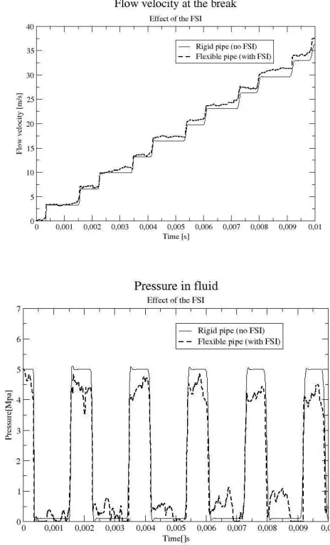
Figure 3 shows the fluid computation results with two modelling hypotheses, by ignoring or taking into account the FSI. The initial pressure value is 50bar.
Figure 3. Fluid computation solutions in terms of the flow velocity (above) and the fluid pressure (below). The solid lines correspond to the results without FSI and the dashed lines for the results with the FSI
activated.
Figure 4. Fluid velocity time evolution at the line break. The steady state is attained at about 150ms.
Structural analysis
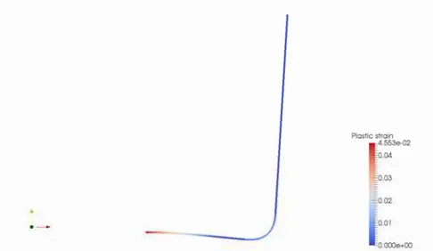
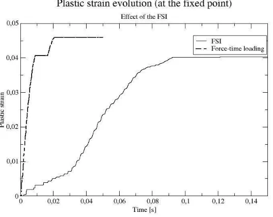
First, the dynamic response is computed with a simplified force-time function, assuming that the fluid velocity increases instantaneously to its steady state value obtained by the fluid calculation (see Figure 4). The plastic strain distribution is shown in Figure 5. Even if the simplified analytical approach predicts a pipe whip for an initial pressure of 28bar, the numerical structural analysis leads only to a maximum plastic strain value of less than 5%, not sufficient to create a plastic hinge, and for a much bigger initial pressure of 50bar. When the FSI is taken into account, the maximum plastic strain value is of about 4%, but its increase is much smaller than for the force-time loading case, as shown in Figure 6.
Figure 6. Maximum plastic strain time evolution, by using a force-time loading function or a direct coupled FSI analysis. When the FSI is taken into account, the plastic strain increase is slower, but attains
a similar maximum value as for the force-time loading.
CONCLUSION
Three modelling approaches are considered to address the analysis of the pipe whip risk due to a HELB: simplified analytical approach, force-time loading numerical structural analysis and fully coupled FSI analysis. They are compared on a simple but representative numerical example. The numerical results show that the simplified analytical approach tends to underestimate significantly the pipeline capacity of resisting to a pipe whip. This trend has already been observed by previous work, but without considering the FSI effects. It is shown here that taking into account the FSI, the pipe whip resistance capacity estimation can be further increased.
REFERENCES
ANSI/ANS 58-2 (1988). “Design Basis for Protection of Light Water Nuclear Power Plant Against the Effect of Postulated Pipe Ruptures”, American Nuclear Society / American Nuclear Standard.
Roemer, R. E. and East, G. H. (1980). “Prediction of Large Deformation Pipe Whip and Barrier Impact: A Simplified Approach”, Pressure Vessels & Piping Conference, ASME pubication.
Micheli, I. and Zanaboni, P. (2003). “An analytical validation of simplified methods for the assessment of pipe whip characteristics”, SMIRT Conference.
Potapov, S. and Galon, P. (2005). “Modelling of Aquitaine II pipe whipping test with the EUROPLEXUS fast dynamics code,” Nuclear Engineering and Design, 235, 2045-2054.