Implementation of Load Frequency Controller
for Multi Area Power System: GA Approach
Roshni Patel 1, Pratik Patel 2, Dr. Ami Patel 3
P.G. Student, Department of Electrical Engineering, MGITER, Navsari, Gujarat, India1 Assistant Professor, Department of Electrical Engineering, MGITER, Navsari, Gujarat, India2
Assistant Professor, Department of Electrical Engineering, GEC, Bharuch, Gujarat, India3
ABSTRACT: In an interconnected power system, as a power load demand varies randomly, in the case of any small sudden load change in any of the areas,both area frequency and tie-line power flow interchange also vary. The main goal of Load Frequency Control (LFC) are, to hold the frequency and the desired power output in the interconnected power system at the scheduled values and to control the change in the tie-line power flow between control areas.In this paper, the Load Frequency Control achieved by implementation of following conventional controller strategies: Proportional-Integral (PI) controller and Proportional-Integral-Derivative (PID) controller technique. A three area load frequency model is constructed in Matlab/Simulink by implementing the GA tuning PI controller and GA tuning PID controller to control the frequency deviations. GA tuning PID controller technique rapidly track the reference frequency of system and better result in respect of rise time, settling time, peak time etc.
KEYWORDS: Load Frequency Control (LFC), Automatic Generation Control (AGC) Proportional-Integral (PI) controller, Proportional-Integral-Derivative (PID) controller, Genetic Algorithm(GA).
I. INTRODUCTION
Nowadays most of power systems are interconnected with their neighboring areas. In a multi area power system, every area has various types of uncertainties and disturbance arising from complexity of the system, system modelling errors and change in power system topology due to fault and switching. In interconnected multi area power system as a power load demand varies randomly, in the case of any small sudden systems are divided into various areas.In an interconnected multi-area power system, as a power load demand varies randomly, in the case of any small sudden load change in any of the areas, both area frequency and tie-line power flow interchange also vary. The main goals of load
frequency control are hold the frequency constant (Δf=0) against any load change [3]. Each area must contribute to
absorb any load change such that frequency does not deviate. And each area must maintain the tie-line power flow to its pre-specified value [6].
Unbalance between supply and load causes the fluctuation of the system frequency, which can degrade the power system performance and makes his control more difficult. LFC has been one of the important control challenges in electric power system stability and control. Automatic generation control plays the major role to maintain system frequency at or very close to a specified nominal value and to sustain the scheduled exchange of power. Load Frequency Control is important to hold the system frequency and the inter-area tie-line power flow as near with neighbouring control areas at the scheduled values. In order to satisfy the LFC objectives, a control error signal named the area control error (ACE) is measured. This signal is a linear combination of net interchange and frequency deviation and represents the real power unbalance between supply and load of power [5]. The area control error (ACE) is given by:
ACE= ΔPtieij +βiΔfi
steam/water which is given to the turbine. Because ultimately electromagnetic torque which produced by turbine is regulated then the generator speed and output power become regulate to its normal value [7]. The main aim of load frequency control is to minimize the transient variations in these variables and also to make sure that their steady state error is zero. Many modern control techniques are used to implement reliable controller. The objective of these control techniques is to produce and deliver power reliably by maintaining both voltage and frequency within permissible range.
II. THREE AREA POWER SYSTEM
Three interconnected area considered in this paper are:
Area-1 is reheat thermal plant Area-2 is Hydro plant and Area-3 is also reheat thermal plant. All these three area are interconnected with tie line.
1) Thermal Unit : A steam turbine converts the energy that is stored in the form of high pressure and high temperature steam into rotating energy, that energy again converted into electrical energy by moving the generator [14].
2) Hydro unit : A hydro turbine converts potential energy of the water into kinetic energy than into rotating energy, than it converted into electrical energy by generators.
Fig.1 Three Area Interconnection
III. DIFFERENT CONTROL METHODOLOGY
A. PI Controller : A PI controller is a special case of the PID controller in which the derivative of the error is not used. The lack of derivative action may make the system more steady in the case of noisy data. This is because derivative action is more sensitive to higher frequency terms in the inputs [5]. Without derivative action, a PI-controlled system is less responsive to real (non-noise) and relatively fast alterations in state and so the system will be slower to reach set-point and slower to respond to perturbations than a well-tuned PID system may be. The proportional-Integral (PI) algorithm computes and transmits a controller output signal at every sample time,T, to the final control element(e.g., valve, variable speed pump).The combination of proportional and integral result the Pi controller, the advantages of PI controller are, increase the speed of the response and also to eliminate the steady state error [8]. B. PID Controller: Proportional integral derivative controllers play a major role in industrial process control because
more than 90 percent of processes in different electrical industries are controlled by PID controllers these days. The PID controllers are arguably the most commonly applied feedback control system [9].
IV.PARAMETER TUNING BY USING GENETIC ALGORITHM
A. Genetic Algorithms are optimization technique, which is inspired by natural selection and natural genetics. It differs from other technique by providing number of candidate solution rather than one candidate solution. Each candidate solution of problem is represented by individual. Population is defined as group of individuals. The process of GA is initialized with a population of random guesses [13]. GA includes operators such as reproduction, crossover, mutation, inversion. The different Genetic Algorithm parameters are listed below.
Table 1. Genetic Algorithm Parameters
Here, multiple objective function are used which are minimized. The objective function used for the system is given below:
Integral square error is given by,
= |∆ |
The objective of optimal GA design is provision of maximum damping, that means to minimize the control parameters like rise time, peak time and settling time in system oscillations. ISE is used in optimal analysis and design.
B. Procedure for GAPSS implementation:
Step 1: Represent the problem variable domain as a chromosome of fixed length, choose the size of a chromosome of population popsize (number of individuals) , the crossover probability pcross, the mutation probability pm, and the termination critrria maxgen.
Step 2: Randomly generate an initial population of chromosomes within the specified upper & lower limit values of the parameters. In this work 6 control gains (parameters), [KP1,KI1,KP2,KI2,KP3,KI3] are being tuned for PI control and also for PID 9 control gains [KP1,KI1,KD1,KP2,KI2,KD2,KP3,KI3,KD3] with the help of GA. And here popsize =10
is defined. So, the initial populations of phenotypes are represented in the form of [10 ×6] and [10 ×9] matrix.
Step 3: Evaluation and selection work on phenotype space, while Genetic operators work on genotype (binary string) space. So, conversion of phenotype to binary string is done by decoding every individual created of popsize.
Step 4: Define fitness function to measure the performance, or fitness of an individual cheomosome in problem domain. The fitness function establishes the basis for selecting chromosome that will be mated during reproduction. The fitness function is defined as Ffit = (Ts+Tr+overshoot+ise).
Step 5: Evaluate the fitness function of each individual of population using fitness function. The objective of GA is to minimize the fitness function.
Step 6: Reproduce population of networks (chromosomes) generated according to their fitness.
Step 7: Select a pair of chromosome for mating from the current population. Parent chromosome are selected with a probability related to their fitness.
Step 8: Create a pair of offspring chromosome by applying the genetic operators, crossover and mutation.
Step 9: Insert the created offspring chromosome in the new population.
Step 10: Repeat the step 7 untill the size of the new chromosome population becomes equal to the size of the initial population.
Step 11: Replace the initial (parent) chromosome population with the new (offspring) population.
Population Size 10 Maximum number of
Generation
Step 12: Go to step 5, to evaluate new created offspring and repeat the process until the termination criterion is satisfied, maximum number of generation is met (maxgen)
V. SIMULATION RESULTS
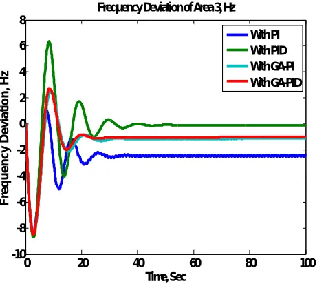
In this present work, three area interconnected thermal-hydro-thermal system has been studied with proposed controller using PI and PID in which the parameter tuning by using Genetic Algorithm and simulated in MATLAB/SIMULINK toolbox. The capacities of areas are Area 1: 2000 MW (Thermal), Area 2: 12000 MW (Hydro), Area 3: 6000 MW (Thermal). Thermal areas are provided with a single reheat turbine. Hydro area have electric governor and hydro turbine. A vast power system network can be partitiond into various smaller load frequency control areas interconnected by means of tie lines. The control objectives to be fulfilled are as follows: (i) each control area as much as possible ought to provide its own load demand and transfer the power through tie line must be done only in the case of the demand of that area being lower than the generation of the units in the specified area. (ii) all control areas should respond to the changes in load frequency control. Analyse the LFC in multi area power system the comparison between GA tuning PI controller and GA tuning PID controller.
Fig.3 Frequency Deviation Of Area 1 Thermal System Fig 4 Frequency Deviation Of Area 2 Hydro System
Fig.5 Frequency Deviation Of Area 3 Thermal System Fig.6 Tie Line Power Deviation Of Area 1-2
Fig. Tie line power deviation of area 1-3
0 20 40 60 80 100
-10 -8 -6 -4 -2 0 2 4 6 8
Time, Sec
F
re
q
u
e
n
c
y
D
e
v
ia
ti
o
n
,
H
z
Frequency Deviation of Area 3, Hz
With PI With PID With GA-PI With GA-PID
0 20 40 60 80 100
-2 -1.5 -1 -0.5 0 0.5
Time, Sec
P
o
w
e
r
D
e
v
ia
ti
o
n
,
M
W
Tie Line Power Deviation Between Area 1-2 , MW
Fig.8 Tie Line Power Deviation Of Area 2-3 Fig.8 Tie Line Power Deviation Of Area 1-3
VI.CONCLUSION
The outcomes from study and after performing MATLAB/SIMULINK ,the automatic generation control is used for regulate the frequency at nominal. And AC tie line is use parallel with DC tie line. Because it improved the system parameter. And disadvantage of AC tie line is overcome by using DC tie line. PI and PID controller is considered to three area generation controls for frequency deviation of each area. The transient behaviour of frequency for the load perturbation in area is studied. In practice, power system generally have more than three areas and each area is different than other. For better improvement of settling time is achieved by online tuning of PI and PID controller by using Genetic Algorithm. Online tuning of PID controller gives better in respect of rise time, settling time, peak time etc. And future work will consider for use of fuzzy logic controller which improves the system accuracy and speed up responses.
REFERENCES
[1] G. R. Hareekaanth, S. Balamurugan, “Analysis and Implementation of Load Frequency Controller for Deregulated Power System”, Biennial International Conference on Power and Energy Systems: Towards Sustainable Energy (PESTS E), IEEE, 2016.
[2] Zhangxin Zhou, Garng M. Huang, Shankar P. Bhattacharyya, “Modern PID Controller Design for Load Frequency Control”, IEEE, 2016. [3] Satish Kumar Meena, Saurabh Chanana, “Load Frequency Control of Multi Area System Incorporating SMES Technology”, IEEE, 2015.
[4] Hassan A. Yousef, Khalfan AL –Kharusi, Mohammed H. Albadi, “Load Frequency Control of a Multi –Area Power System: An Adaptive Fuzzy Logic Approach”, IEEE TRANSACTIONS ON POWER SYSTEMS, 2014.
[5] Satish Kumar Meena , Saurabh chanana, “Comparative study of load frequency control using PID and FGPI controller”, IEEE Transaction, 2014. [6] M. M. M. H. a. M. B. Nour EL Yakinekouba, “Load Frequency Control in Multi Area Power System Based On Fuzzy Logic-PID Controller”, in IEEE,2015. [7] A. U. a. B. Divakar, “Simulation study of Load Frequency Control of Single and Two Area Systems”, pp. 214-219,2012.
[8] L. D. Yao Zhang2, “Load Frequency Control For Multiple-Area Power Systems,” pp. 2773- 2778, 2009.
[9] B. N. D. S. A. C. B. V. E. B. K. Jagathesan, “Automatic Generation Control Of An Interconnected Multi –Area Rheat Thermal Power Systems with Conventional Proportional Integral Controller Considering various performance Indices,” pp. 289-294, 2016.
[10] D. A. S. A. V. E. B. K. Jagatheesan, “Conventional Controller Based AGC of multi-area Hydro- Thermal Power Systems,” pp. 1-6, 2016. [11] L. C. S. S. K. D. Puja Dash1, “AGC of a Multi-Area Hydro- Thermal System with BES and Firefly Optimized PID Controller,”pp.1-6, 2016.
[12] M. G. R. N. K. a. O. S. M. Suman1, “Load Frequency Control Of Three Unit Interconnected Multi Machine Power System With PI andFuzzy Controllers,” pp. 1-5, 2012.
[13] P. S. Biswas , “GA Application to Optimization of AGC in Two Area Power System Using Bettery Energy Storage”, pp. 314-344,2012. [14] Satish Kumar Meena, Saurabh Chnana, “ Load Frequency Contro of Multi Area System Incorporating SMES Technology”, IEEE,2015.
0 20 40 60 80 100
-2 -1.5 -1 -0.5 0 0.5 1 Time, Sec P o w e r D e v ia ti o n , M W
Tie Line Power Deviation Between Area 2-3, MW
With PI With PID With GA-PI With GA-PID
0 20 40 60 80 100
-1.5 -1 -0.5 0 0.5 1 1.5 Time, Sec P o w e r D e v ia ti o n , M W
Tie Line Power Deviation Between Area 1-3, MW