PARAMETRIC STUDY OF FLEXIBILITY FACTOR FOR CURVED PIPE
AND WELDING ELBOWS
Oleg Kireev1, Dmitry Kireev2 and Alexey Berkovsky3
1
Principal, CKTI-Vibroseism, Saint Petersburg, Russia ([email protected])
2
Engineer, CKTI-Vibroseism, Saint Petersburg, Russia
3
Principal, CKTI-Vibroseism, Saint Petersburg, Russia
ABSTRACT
It is known that thin-walled curved pipes or welded elbows under bending exhibit significantly higher flexibility than straight pipe of the same cross-section. To address this phenomena different piping Codes and Standards based on the elementary beam theory introduce in analysis a so called “flexibility factor” for correction of the bending stiffness of the bend elements. The accuracy of these coefficients used in analyses to a large extent determines the precision of the calculated stresses in piping components and loads on the supporting structures and connected equipment (turbines, pumps, etc.).
Despite the fact that behavior of piping bends in operational conditions are well studied, almost all existing piping Codes and Standards establishing flexibility factors for bends do not consider the influence of "end effects" (constraints of the bend ends by the adjacent straight pipes). Chapter NB-3680 of ASME BPVC has for many years contained a note that "The flexibility of a curved pipe or welding elbow is reduced by end effects, provided either by the adjacent straight pipe or by the proximity of other relatively stiff members which inhibit ovalization of the cross section". But nowadays, the only normative document where this effect explicitly is taken into account is the ASME Code Case N-319-3, but its scope is limited by butt welding elbows per ANSI B16.9 and ANSI B16.28 with ratio R/r=2 and 3.
This paper presents results of a finite element study performed to determine the flexibility factors for curved pipes under internal pressure and subjected to in-plane and out-of-plane bending. The influence of end effects are considered as well. The study covers the whole range of geometrical parameters of bends used in design for industry, conventional and nuclear power plants (2<R/r<12, 2<r/t<50, and 15°<<180°). Obtained results can be used to improve the existing regulatory documents related to the stress analysis of nuclear and industrial piping.
INTRODUCTION
Practically all contemporary piping Codes and Standards contain a formula for the bend's flexibility factor that is based on the analytical solution developed by Rodabaugh and George (1957). This coefficient takes into account effect of the internal pressure, but does not consider influence of the end effects. According to this solution flexibility factor is calculated by the following formula:
1
1 / (1 1.5 ) p
k d (1)
where d1 can be obtained by fifth-order approximation from the following recursive dependencies:
2 2
5 4 5
2 2
3 4 2 3
2
1 2 1 1
101 163350 19800 65 42336 8064 1482,25/ 37 7350 2520 506,25/ 17 600 480 110,25/
5 6 24 6,25/ 3 /
a a a
a a a a
a a d a
(2)
where tR r/ 2 12 and PR2/Ert
.
1.65 1 1 ( / )
p
k
k
h Pr tE X
(3)
where 6( / )43( / )13
k
X r t R r .
Influence of the end effects was studied in the work
Rodabaugh
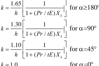
et al. (1978). This research was based on the Finite-Element Method (FEM) analyses performed for 24 models of piping bends with variation of its geometrical parameters: R/r=2 and 3; h=0.05÷1.5; =45°, 90°, 180°. Calculations were undertaken in the linear formulation and did not take into account an internal pressure. These results formed the basis of the Code Case N-319-3 (2010) for Class 1 piping. According to the Code Case in-plane bending flexibility factor for elbows welded on both ends to straight pipes with length not less than two times the nominal outside diameter of the elbow can be calculated as follows:1.65 1
1 ( / ) k
k
h Pr tE X
for 180
1.30 1
1 ( / ) k
k
h Pr tE X
for =90 (4)
1.10 1
1 ( / ) k
k
h Pr tE X
for =45
1.0
k for =0
Linear interpolation with shall be used for between 180° and 0°; k shall not be less than 1.0. Since the background FE calculations were performed for elbows with R/r=2 and 3, the implementation of the Code Case is limited: it could be used for evaluation of stresses in butt welding elbows per ANSI B16.9 MSS-SP87 or ANSI B16.28.
PROBLEM FORMULATION
Figure 1 shows a general arrangement of the model used for the calculation of the flexibility factor.
Figure 1. General arrangement of the model
while the left flange is fixed. Angular deflections x, y and z at the point where loads are applied could
be found from the classical beam theory taking into account corrected by flexibility factor stiffness EI/ki
for the in-plane bending and EI/ko for out-of-plane. From the other hand an actual angles could be
derived from the FE analysis. Then, flexibility factors may be calculated by the following formulas:
in-plane bending: i( z) z 2 z
EI L
k M
M R R
(5)
out-of-plane bending:
2
sin 2 sin
( ) (1 ) 1 cos
2 2 2
o x x
x
EI L
k M
M R R
(6)
2
sin 2 sin
( ) (1 ) 1 sin
2 2 2
o y y
y
EI L
k M
M R R
(7)
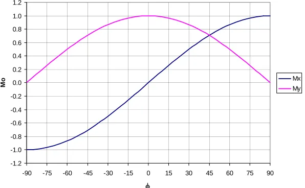
As it follows from the formulas presented above out-of plane flexibility factor may be calculated either from (6) or (7). Figure 2 presents distribution of the bending moment Mo along bend's length for the
out-of-plane loading by Mx and My. It could be seen that Mx affects mainly parts of the elbow adjacent to
the straight pipe, while My influences mostly a central part of the bend. Since the effect of adjacent pipes
is more sound near the end parts of the elbow and is not significant in the central part, one can expect that flexibility factor due to Mx will be lower than due to My. It leads to the observation that for out-of-plane
bending a flexibility factor will further depend on the direction of the combined applied moment
M= Mx + My.
-1.2 -1.0 -0.8 -0.6 -0.4 -0.2 0.0 0.2 0.4 0.6 0.8 1.0 1.2
-90 -75 -60 -45 -30 -15 0 15 30 45 60 75 90
Mo
Mx My
Figure 2. Distribution of the bending moment along the elbow
Taking into account that piping Codes utilize only one flexibility factor for the in-plane as well as for out-of-plane bending this study is limited by consideration of the maximal value derived from the equation (7).
To perform a qualitative and quantitative evaluation of the flexibility factor the following range of geometrical parameters was considered: : 15°, 30°, 45°, 60°, 90°, 180°; R/r: 2, 3, 6, 9, 12; r/t: from 2 to 50 (20 values in geometric sequence).
The maximal values of the internal pressure and bending moment were determined taking into account provisions of ASME B31.1 (2010). Following to the Code allowables and assuming Smax = 200
MPa, the maximal internal pressure and bending moment are:
max max
S t P
r
; max max
1.5S Z
M
i
Analyses were performed for variation of the pressure and moment in the following diapason: P
= p*Pmax; p = 0, 0.25, 0.5, 0.75, 1.0. M = m*Mmax; m = 0, 0.25, 0.5, 0.75, 1.0.Young Modulus was taken
as E = 200000 MPa, Poisson ratio ν = 0.3.
FINITE ELEMENT MODEL
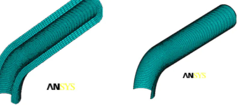
All calculations were undertaken with use of ANSYS version 13. Taking into account that presented study consider thin-walled elbows (r/t=50) as well as thick-walled (r/t=2) ones, a sensitivity analysis was performed for different types of finite elements: SOLID 186, SHELL 181 and SHELL 281. Based on the obtained results, it was decided to use SOLID 186 for the further analyses.
The boundary conditions imposed on the finite element models took into account a symmetry of the elbow under certain loading: for in-plane bending a quarter of the bend was used, while for out-of-plane loading one half of the elbow was considered. Elbow cross-section was divided into 72 elements. Size of elements in the longitudinal direction was taken 1.8 times higher than in transverse. Depending on the elbow wall thickness one to four elements were used in radial direction. Figure 3 shows samples of ANSYS FE models.
Thick-walled elbow under in-plane bending Thin-walled elbow under in-plane bending Figure 3. FE mesh
Rigid flange was modeled with use of following elements: CONTA174 with option "Rigid Surface Constraint" and TARGE170 element with option "Pilot Node". Pilot node was used to apply bending moment and to define resulting angle for consequent calculation of the flexibility factor. Due to non-linear interaction of the internal pressure and bending moment for the curved pipe bending all analyses have been undertaken in geometrical non-linear formulation (ANSYS option NLGEOM, ON).
Internal pressure was applied as distributed load to the inner surface of the FE model, together with an axial tension equivalent to the internal pressure applied at the end of pipe to simulate the closing end.
SENSITIVITY ANALYSIS AND PRELIMINARY CALCULATIONS
with variation of the adjacent pipes length L from 0.1*r to 20*r. Some results illustrating the influence of length L on the flexibility factor are shown in Figure 4. To be more evident calculated flexibility factors
k(L) are normalized to the case when mentioned edge effects are obviously insignificant (for L = 20r). From the presented pictures it's clear that influence of the "rigid flange" on the flexibility factor becomes negligible when L 5r.
0.00 0.20 0.40 0.60 0.80 1.00 1.20
0.1 1.0 10.0 100.0
k / k( L/ r= 2 0 ) L/r
Min(r/t=20; R/r=3; p=0; m=0.1)
0.00 0.20 0.40 0.60 0.80 1.00 1.20
0.1 1.0 10.0 100.0
k / k( L /r = 20 ) L/r
Min(=90; R/t=20; p=0; m=0.1)
R/r=2 R/r=3 R/r=6 R/r=9 R/r=12
variation of the bend's angle variation of R/r Figure 4. Influence of the adjacent straight pipes length on the flexibility factor
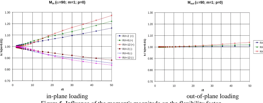
FE analysis in geometrically nonlinear formulation brings an additional influencing factor: an absolute value of the bending moment. This factor appears when the problem is solved by finite-displacement analysis and was not considered in the theoretical work by Rodabaugh &
George
(1957). To study this effect some additional analyses were carried out: the value of the bending moment was varied in the range (0.01 ÷ 1)*Mmax, where Mmax was defined by equation (8). Results of this study (Figure5) allow to conclude that the magnitude of the bending moment has practical influence on the flexibility factor for in-plane loading and under the moment with magnitude close to the maximal value difference can reach as high as 25%. At the same time flexibility of the elbow increases with closed moment and decreases with opened moment. Under the out-of-plane loading the flexibility factor practically does not depend on the magnitude of the moment.
Taking into account results presented above, all consequent analyses were carried out with L = 5r and M = 0.1*Mmax.
0.70 0.80 0.90 1.00 1.10 1.20 1.30
0 10 20 30 40 50
k / k( m = 0. 0 1) r/t
Min(=90; m=1; p=0)
R/r=2 (+) R/r=6 (+) R/r=12 (+) R/r=2 (-) R/r=6 (-) R/r=12 (-) 0.70 0.80 0.90 1.00 1.10 1.20 1.30
0 10 20 30 40 50
k / k (m = 0. 01) r/t
Mout(=90; m=1; p=0)
R/r=2 R/r=6 R/r=12
in-plane loading out-of-plane loading
RESULTS OF PERFORMED ANALYSES
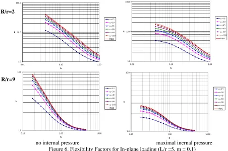
The complete set of performed FE calculations for in-plane bending includes variation of the different parameters influenced on the flexibility factor. Variation was made for the following bend angles: = 15, 30, 45, 65, 95, 180. Internal pressure parameter p was varied from 0 to 1 with step 0.25. R/r parameter was varied as R/r=2, 3, 6, 9, 12 and relative wall thickness was considered in the range of 2 r/t 50 (20 values were taken in the geometric sequence). Figure 6 shows selected results from this stage.
1.0 10.0 100.0
0.01 0.10 1.00
h k R&G 1.0 10.0 100.0
0.01 0.10 1.00
h k R&G 1.0 10.0
0.10 1.00 10.00
h k R&G 1.0 10.0
0.10 1.00 10.00
h k R&G
no internal pressure maximal inernal pressure Figure 6. Flexibility Factors for In-plane loading (L/r =5, m = 0.1)
A theoretical solution for the flexibility factor does not differ between in-plane and out-of-plane bending. However an actual FE study considered both variants of the loads. From this perspective for out-of-plane loading a comparison with in-plane bending was performed. Figure 7 shows the differences in the flexibility factors calculated for in-plane and out-of-plane bending moments. As it follows from the obtained results the maximal difference does not exceed 5%.
-10.0% -8.0% -6.0% -4.0% -2.0% 0.0% 2.0% 4.0% 6.0% 8.0% 10.0%
0.01 0.10 1.00
h (k o u t-k in )/ k in -10.0% -8.0% -6.0% -4.0% -2.0% 0.0% 2.0% 4.0% 6.0% 8.0% 10.0%
0.10 1.00 10.00
h (k o u t-k in )/k in
Figure 7. Comparison of Flexibility Factors for In-plane vs. out-of-plane loading (L/r =10, m = 0.1) R/r=2
R/r=9
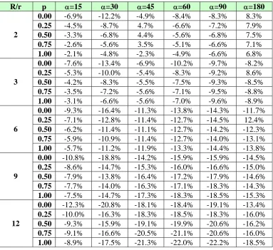
Comparison of the obtained FE results with the Code Case N-319-3 has a practical value. Code Case is applicable only for elbows with adjacent straight pipes L > 2Do. Carrying out such comparative
analysis one should take into account that error of 25% in the calculation of the flexibility factor at k=1.5 would affect the overall piping stiffness considerably less than at the value k=20. That is why it was decided to use for analysis an elbow with adjacent straight pipes. The following equation was utilized to quantify results:
2( / ) ( / )
1 100%
2( / ) ( / )
CODE
FEA
L r k R r
Diff
L r k R r
(9)
where kcode- flexibility factor calculated according the Code Case; kFEA - results from FE analysis. Table 1
summarizes this comparison.
Table 1. Flexibility Factor Code Case vs. FEA comparison
R/r p =15 =30 =45 =60 =90 =180
0.00 -6.9% -12.2% -4.9% -8.4% -8.3% 8.3%
0.25 -4.5% -8.7% 4.7% -6.6% -7.2% 7.9%
0.50 -3.3% -6.8% 4.4% -5.6% -6.8% 7.5%
0.75 -2.6% -5.6% 3.5% -5.1% -6.6% 7.1%
2
1.00 -2.1% -4.8% -2.3% -4.9% -6.6% 6.8%
0.00 -7.6% -13.4% -6.9% -10.2% -9.7% -8.2%
0.25 -5.3% -10.0% -5.4% -8.3% -9.2% 8.6%
0.50 -4.2% -8.3% -5.5% -7.5% -9.3% -8.5%
0.75 -3.5% -7.2% -5.6% -7.1% -9.5% -8.8%
3
1.00 -3.1% -6.6% -5.6% -7.0% -9.6% -8.9%
0.00 -9.3% -16.4% -11.3% -13.8% -14.3% -11.7%
0.25 -7.1% -12.8% -11.4% -12.7% -14.5% 12.4%
0.50 -6.2% -11.4% -11.1% -12.7% -14.2% -12.3%
0.75 -5.9% -10.9% -11.4% -12.7% -14.0% -13.1%
6
1.00 -5.7% -11.2% -11.9% -13.3% -14.4% -13.8%
0.00 -10.8% -18.8% -14.2% -15.9% -15.9% -14.5%
0.25 -8.6% -14.7% -15.3% -16.0% -16.6% -15.0%
0.50 -7.9% -13.8% -16.4% -17.2% -17.9% -14.6%
0.75 -7.7% -14.0% -16.3% -17.1% -18.3% -14.3%
9
1.00 -7.5% -14.7% -17.3% -18.3% -18.5% -15.3%
0.00 -12.3% -20.8% -18.1% -18.4% -19.1% -13.4%
0.25 -10.0% -16.3% -18.3% -18.5% -18.3% -16.0%
0.50 -9.3% -15.9% -19.1% -19.9% -20.6% -16.2%
0.75 -9.1% -16.6% -20.5% -21.1% -20.6% -16.0%
12
1.00 -8.9% -17.5% -21.3% -22.0% -22.2% -18.5%
It could be seen from the above table, that error ~10% is observed for the elbows with R/r=2÷3 and its value increases up to 20% for the bends with R/r = 12.
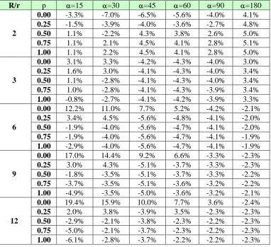
Flexibility factor for the case of in-plane bending can be calculated by the more precise equation:
p
k
k
(10)
where kp is a flexibility factor defined from the theoretical solution (1), is "end effects" correction:
min(A R r h( / )b c;1)
(11)
Table 2. Coefficients used for the "end effects" correction
=15 =30 =45 =60 =90 =180 A 0.414 0.492 0.570 0.665 0.786 0.97
b 0.264 0.238 0.188 0.144 0.081 0
c 0.2 0.05 0 0 0 0
For the intermediate values of the bend angle a flexibility factor k can be determined by linear interpolation. For = 0 k = 1. This formula is applicable for 2≤R/r≤12. For a large values of R/r results for R/r = 12 may be used.
The Table 3 shows a summary of comparison of the flexibility factor calculated by FE analysis vs. values from Equation (10).
Table 3. Flexibility Factor Eq.(10) vs. FEA comparison
R/r p =15 =30 =45 =60 =90 =180
0.00 -3.3% -7.0% -6.5% -5.6% -4.0% 4.1%
0.25 -1.5% -3.9% -4.0% -3.6% -2.7% 4.8%
0.50 1.1% -2.2% 4.3% 3.8% 2.6% 5.0%
0.75 1.1% 2.1% 4.5% 4.1% 2.8% 5.1%
2
1.00 1.1% 2.2% 4.5% 4.1% 2.8% 5.0%
0.00 3.1% 3.3% -4.2% -4.3% -4.0% 3.0%
0.25 1.6% 3.0% -4.1% -4.3% -4.0% 3.4%
0.50 1.1% -2.8% -4.1% -4.3% -4.0% 3.4%
0.75 1.0% -2.8% -4.1% -4.3% -3.9% 3.4%
3
1.00 -0.8% -2.7% -4.1% -4.2% -3.9% 3.3%
0.00 12.2% 11.0% 7.7% 5.2% -4.2% -2.1%
0.25 3.4% 4.5% -5.6% -4.8% -4.1% -2.0%
0.50 -1.9% -4.0% -5.6% -4.7% -4.1% -2.0%
0.75 -1.9% -4.0% -5.6% -4.7% -4.1% -1.9%
6
1.00 -2.9% -4.0% -5.6% -4.7% -4.1% -1.9%
0.00 17.0% 14.4% 9.2% 6.6% -3.3% -2.3%
0.25 3.0% 4.3% -5.1% -3.7% -3.3% -2.3%
0.50 -1.8% -3.5% -5.1% -3.7% -3.3% -2.2%
0.75 -3.7% -3.5% -5.1% -3.6% -3.2% -2.2%
9
1.00 -4.9% -3.5% -5.0% -3.6% -3.2% -2.1%
0.00 19.4% 15.9% 10.0% 7.7% 3.6% -2.4%
0.25 2.0% 3.8% -3.9% 3.5% -2.3% -2.3%
0.50 -2.9% -2.1% -3.8% -2.3% -2.2% -2.3%
0.75 -5.0% -2.1% -3.7% -2.3% -2.2% -2.3%
12
NOMENCLATURE
Do - pipe or elbow outside diameter, mm t - pipe or elbow wall thickness, mm
r - pipe or elbow mean radius, mm
R - bend radius, mm
- arc angle of elbow, rad
E - modulus of elasticity, MPa
- Poisson’s ratio
I - plane moment of inertia, mm4
Z - section modulus, mm3
L - length of straight pipe, mm
P - internal pressure, MPa
S - allowable stress, MPa
M - applied moment, N-mm (Mi- in-plane; Mo- out-of-plane; Mt- torsional) h - flexibility characteristic (h=tR/r2)
k - flexibility factors
kp - flexibility factors (no end effects) i - stress-intensification factor (i=0.9/h2/3)
CONCLUSIONS
1. The effect of the elbow's ends constraining by the adjacent straight pipes ("end effect") was studied for the wide range of the geometrical parameters and loading conditions
2. The influence of the adjacent straight pipes on the elbow's flexibility factor was considered. It was shown that this influence is insignificant when L>5r. At the same time it was recognized that for the thin-walled bends with the small angles and large R/r ratio this length L should be higher than 10r.
3. It was shown that an additional influencing factor, an absolute value of the bending moment, appears when solution is found by finite-displacement analysis in the geometrically nonlinear formulation. Practically, for the in-plane bending this factor could bring scattering in results up to ±25% depending on the direction of moment (closed or opened). It was also shown that for the elbows under the out-of-plane bending the flexibility factor practically does not depend on the magnitude of the applied moment.
4. It was shown that a flexibility factor for the elbow loaded by out-of-plane moment My is
practically the same as for in-plane loading. From the other hand, Mx loading leads to the smaller
values of flexibility factor. Taking into account that actual Codes and Standards use only one flexibility factor for Mx and My, it would be useful to investigate this effect in further studies.
5. As result of this study an accurate formula for the flexibility factor is suggested. This expression takes into account the "end effects" and demonstrates a good compliance with FE analyses for the complete range of the elbow/bend geometrical parameters encountered in practice for nuclear and industry piping.
REFERENCES
ASME Code Case N-319-3, (2010) "Alternate Procedure for Evaluation of Stresses in Butt Welding Elbows in Class 1 Piping, Section III, Division 1", Cases of ASME Boiler and Pressure Vessel Code, ASME, New York, 2010
ANSI/ASME B31.1-2010, (2010) Power Piping, American Society of Mechanical Engineers, 2010 Rodabaugh E.C.., George H.H. (1957), "Effect of internal pressure on flexibility and stress-intensification
factors of curved pipe or welding elbows ", Trans. ASME, vol. 79, No.4