Inter Carrier Interference Cancellation in
OFDM Systems under Different Channeling
Environments
N.Mounika1, P.Ratna Bhaskar2
P.G. Student, Department of Electronics and Communication Engineering, SRKIT, Enikepadu, Vijayawada, India1 Assistant Professor, Department of Electronics and Communication Engineering, SRKIT, Enikepadu, Vijayawada,
India2
ABSTRACT: Inter carrier Interference (ICI) is the most prevalent effect that is observed in orthogonal frequency
division multiplexing (OFDM) systems. This may be due to the Doppler shift or phase noise. In this paper, a parallel cancellation algorithm is proposed in space frequency domain to mitigate the ICI. The performance of this approach is evaluated under different channeling environments. Experimental results show that the proposed space frequency parallel cancellation proves better in different SUI channeling environments when compared against the conventional parallel cancellationscheme.
KEYWORDS: Inter Carrier Interference, OFDM, Space Frequency Parallel Cancellation, SUI
I. INTRODUCTION
Orthogonal frequency division multiplexing (OFDM) communication system has number of advantages over conventional communication techniques namely FDMA, TDMA and CDMA. Orthogonal frequency division multiplexing (OFDM) communication system has better spectral efficiency, high data rate, low inter carrier interference and moreover it is termed as future generation communication system because of its flexible and reliable high speed data rates, high spectral efficiency, high quality service and robustness against narrow band interference and frequency selective Fading.
In orthogonal frequency division multiplexing (OFDM) all subcarriers are orthogonal to each other which results in correlation between the subcarriers. Although orthogonal frequency division multiplexing (OFDM) supports wide range of advance applications with high data rate .In the MCM (multi carrier modulation), OFDM yields good results over Frequency division multiplexing (FDM). Generally OFDM is considered as optimal version of the MCM schemes and respective representations are as follows.
Fig. 1(a) Conventional FDM in MCM
Fig. 1(b) OFDM Multicarrier modulation technique
Frequency
II. RELATED WORK
In OFDM (Orthogonal frequency division multiplexing), the multiple frequency channels (sub-carriers) are orthogonal to each other. But the major problem of OFDM is frequency offset sensitivity between the transmitted and received signals, may be due to Doppler shift of the channel, or the difference between the transmitter and receiver local oscillator frequencies. This carrier frequency offset causes loss of orthogonality among sub-carriers and then signals carried by sub-carriers become dependent on each other, which leads to inter-carrier interference. Researchers have proposed various techniques to combat the ICI in OFDM systems [1].
Various ICI mitigation schemes such as self-cancellation (SC) and the parallel cancellation (PC) scheme have been proposed [2-5]. The SC method in [2] applies the repetitive transmission in a per-subcarrier basis, while the parallel cancellation (PC) [3-5] applies the repetitive transmission in a per-OFDM symbol basis.
In this paper, the parallel cancellation scheme is extended to be implemented in space frequency domain thus forming space frequency parallel cancellation OFDM system. The parallel cancellation scheme lowers error floor for OFDM systems in frequency selective fading channels with Doppler frequency. This characteristic is inherently extended to the SFPC-OFDM system and improves the BER significantly.
This paper is organized as follows. The OFDM system model is discussed in section III. Section IV presents the Parallel Cancellation Scheme and corresponding architecture of the Transceiver. Section V describes the SF-OFDM system. Section VI presents the SFPC scheme. Simulation results are discussed in section VII. Conclusions are presented in section VIII.
III. OFDM SYSTEM MODEL
The main disadvantage of the OFDM system is its susceptibility to the small differences in frequency at the transmitter and the receiver which is referred as frequency offset. This offset may be occurred due to the Doppler shift that is due to the relative motion between the transmitter and the receiver. A clear mathematical analysis is formulated below. The baseband transmitted signal after IFFT is
2 1
0
N j kn N
k n
n
x
d e
(3.1)
Where k=0, 1…N-1, dn is the data symbol. After adding a cyclic prefix with a length ‘G’ to the signal and a parallel to
serial conversion, the signal is transmitted. The received signal is the convolution of channel impulse response and the transmitted symbols plus the additive white Gaussian noise. After the removal of the cyclic prefix, the recovered base band signal is represented as
(3.2)
1 0 0 0, N
m n n n m
n n m
H d u
H d u
m=0… Where
1 mod sin .sin . N j n mN n m
N
n m N
e n m
u
N n m
2 ( ) 2
1 1
0 0
1
N N j n k j mkN N
n n n k
H d e
e
N
2 1 01
N j mk Nm k
k
d
r e
The weighting function of the data symbols in regular OFDM system is shown in Fig 2.
Fig. 2 weighting function of the data symbols
To mitigate ICI, the parallel cancellation algorithm is developed with the basic idea of having second path that provides the curve of weighting factors with a right shift when Ɛ>0. Next sections will discuss briefly about this method.
IV. PARALLEL CANCELLATION APPROACH
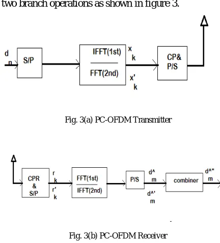
The PC- OFDM approach has two branch operations as shown in figure 3.
Fig. 3(a) PC-OFDM Transmitter
Fig. 3(b) PC-OFDM Receiver
The upper branch is a regular OFDM system which has an IFFT processing at the transmitter and FFT processing at the receiver as shown in Fig 3. The lower branch requires FFT operation at the transmitter as follows.
2 1 '
0
N j kn N
k n
n
x d e
k=0, 1…N-1
(4.1)
The lower branch requires an IFFT operation as follows at the receiver
0 1 2 3 4 5 6 7 8
-0.8 -0.6 -0.4 -0.2 0 0.2 0.4 0.6 0.8 1
(n-m)modN
W
e
ig
h
ti
n
g
F
u
n
c
ti
o
n
fig1. Weighting function of data symbols in the regular OFDM
2 1
' '
0
1
N j m k Nm k
k
d
r e
N
2 ( ) 2
1 1
'
0 0
1
N N j n k j mkN N
n n n k
d H e
e
N
`
1 ' ' 0 0 , Nm m n n n m
n n m
H d v
H d v
(4.2)
Where
(4.3)
Fig. 4 The magnitude of weighting function for the PC-OFDM system
Note that is similar to but the sign of (n-m) is swapped. Let us assume that, by using time division multiplexing (TDM) or frequency division multiplexing (FDM), both 1st and 2nd branches are combined coherently without interfering with each other. The final detected symbol is the sum of the detected symbols as follows.
1
" ' '
0 0
0 ,
N
m m m m n n m n n m n
n n m
d H u H v d H u H v d
(4.4)
The first component is the desired signal component and the rest of the term represents the ICI term. Fig 4 depicts the combined weights with N=16.
V. SPACE FREQUENCY OFDM SYSTEMS
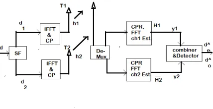
The diversity in SF transmitter and receiver is shown in fig 5. At the transmitter the input vector is = [ … … … ] . In this system, two length N blocks are formed via SF coding for upper and lower branches as two parallel input data vectors as follows
* *
1 0 1
...
2 1T
N N
d
d
d
d
d
, (5.1)
0 2 4 6 8 10 12 14 16 0 0.1 0.2 0.3 0.4 0.5 0.6 0.7 0.8 0.9 1 (n-m)modN W e ig h ti n g F u n c ti o n
fig3. The magnitude of weighting factors of the PC system
PC
1 m od sin. sin .
N j m n
N n m
N
n m N
e m n
v
N m n
* *
2 1 0
...
1 2T
N N
Fig. 5 Block diagram of SF-OFDM transceiver
At time‘t’, d1 and d2 are sent to two parallel IFFT’s and transmitted with CP via transmit antennas T1 and T2
respectively. After Cyclic prefix removal, the two received signal vectors y1 and y2 at time‘t’ after FFT are combined as
2
1 1 1 2 2
y
y
y
H d
H d
(5.2)Where H1 and H2 are two diagonal matrices. The diagonal elements of H1 and H2 are FFTs of respective channel
impulse responses h1 and h2 for the T1 and T2 transmit antennas respectively. Similarly the even and odd matrices of
H1and H2 can be expressed respectively as and and and .
Assuming that channel responses are known or can be estimated at the receiver and also assume that fading is constant across two adjacent subcarriers or
H
1e
H
1o andH
2e
H
2o. The decision variables are obtained as follows:
2 2
* *
1 2 1 2
e e e o o e O e
d
H
y
H y
H
H
d
(5.3)
2 2
* *
2 1 2 1
o e e o o e O o
d H y H y H H d
(5.4)
By combining and , we get the estimate vector .
VI. PROPOSED APPROACH
The PC and SF-OFDM techniques are integrated naturally as both the techniques are per OFDM symbol basis. As depicted in fig 6,two length N vectors are formed as input data vectors at the transmitter as defined in (4.1) and (4.2).Then the d1 and d2 are sent to two parallel branches for upper IFFT and lower FFT at time ‘t’. Demultiplexng
Fig. 6 Proposed approach block diagram (SFPC)
After CPR, for demodulating the received signal from T1, the upper branch employs FFT. Similarly for demodulating the received signal from T2, the lower branch employs an IFFT operator. The two received signal vectors are combined as
2
1 2 1 1 2
y
y
y
H d
H d
(6.1)Equivalently the even and odd vectors of ‘y’ are
and
=
+
=
−
+
The decision variables are obtained as follows:
(6.3)
(6.4)
By combining and , we get the estimate vector .
SUI CHANNEL MODEL:
The Stanford University Interim (SUI)channel response depends upon the key components like path loss, shadowing, multi path fading, Doppler spread, Co channel and adjacent channel interference. The model parameters are varied according to the atmospheric conditions and these depends upon terrain, tree density, antenna height and beam width and also these parameters are random in nature and only statistical averages are used to characterize them, i.e. in terms of the mean and variance value. Based on all above constraints SUI channels were proposed.
These channel models can be used for simulations, design, and development and testing of technologies suitable for fixed, broadband wireless applications. The parameters of SUI channel models are given below.
SUI channel model parameters:
Cell Size: 7Km
BTS antenna height: 30 m
1 1 2 2
e e e e e
y
H d
H d
H d
1e e
H d
2e o* *
1 2
e e e o o
d
H
y
H y
2 2
1e 2O e
H
H
d
* *
2 1
o e e o o
d
H
y
H y
2 2
2e 1O o
H
H
d
Receive antenna height: 6m
BTS antenna beam width: 120
Receive antenna beam width: Omni directional
Polarization: Vertical only
90% cell coverage with 99.9% reliability at each location covered
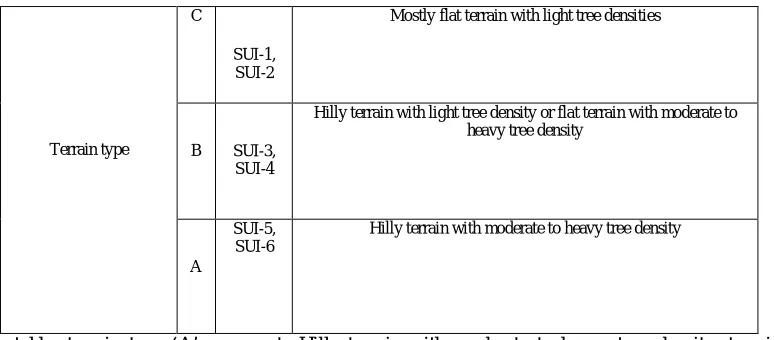
The following table represents the classification of SUI channel models based on terrain and tree densities. It consider three Terrain types A,B and C and 6 SUI channels.
SUI-1 and SUI-2 channels belong to terrain type ‘A’,SUI-2 and SUI-4 belong to terrain type ‘B’ and SUI-5 and SUI-6 belong to terrain type ‘C’.
TABLE 1: CLASSIFICATION OF SUI CHANNELS BASED ON TERRAIN, TREE DENSITY
Terrain type
C
SUI-1, SUI-2
Mostly flat terrain with light tree densities
B SUI-3, SUI-4
Hilly terrain with light tree density or flat terrain with moderate to heavy tree density
A
SUI-5, SUI-6
Hilly terrain with moderate to heavy tree density
In the above table, terrain type ‘A’ represents Hilly terrain with moderate to heavy tree density, terrain type ‘B’ represents Hilly terrain with light tree density or flat terrain with moderate to heavy tree density, terrain type ‘C’ represents Mostly flat terrain with light tree densities
The Stanford University Interim (SUI) channel models are selected for the wireless channel in proposed method for the simulation to yield the better result in equipped way.
VII. EXPERIMENTAL RESULTS
Fig. 7 BER performance for the proposed and SFBC schemes under different sub carriers
The proposed SFPC scheme is compared with the SF scheme in Fig 7 with different block sizes. It shows the BER performance for the proposed and SF schemes under different subcarriers with maximum Doppler frequency of 100Hz and SFPC scheme outperforms the SF scheme in all cases.
Fig. 8 BER performance for the proposed and SF schemes under different Doppler frequencies
Fig 8 shows the BER comparison of PC-,SF-,SFPC-OFDM systems with different Doppler frequencies with a fixed block size of N=512.The SFPC scheme outperforms the SF scheme which is better than that of PC scheme. The BER performance is better in all the three cases.
5 10 15 20 25 30 35 40
10-5 10-4 10-3 10-2 10-1 100
--EBNo (dB)
---B
E
R
SFBC N=256 SFPC N=256 SFBC N=512 SFPC N=512 SFBC N=1024 SFPC N=1024 SFBC(N=1024)
SFPC(N=1024)
SFBC(N=512)
SFPC(N=512)
SFBC(N=256) SFPC(N=256)
5 10 15 20 25 30 35 40
10-3 10-2 10-1 100
--EBNo (dB)
---B
E
R
SF-50 SFPC -50 PC-50 SFPC-100 PC -100 SF -100 PC Doppler=100Hz
PC Doppler=50Hz
SF Dopppler=100Hz SFPC Doppler=100Hz
Fig. 9 BER performance for the proposed and SF schemes under different sampling frequency and Doppler shifts
The above Fig shows the BER performance of SF and SFPC-OFDM schemes with maximum Doppler frequency of 100Hz under different block sizes. The SFPC scheme outperforms the SF scheme regardless of the OFDM block size in terms of BER performance.
Fig. 10 BER performance for the proposed and SFBC under SUI channel with different sub carriers
Simulation results are tested for the proposed approach under different SUI channels. The result shows that for 256 subcarriers the proposed approach is showing better results however at 1024 subcarriers it outperforms than the conventional parallel conventional ICI cancellation algorithm.Simulation results in
S
tanford University Interim (SUI) channel model confirm the superb performance in SFPC-OFDM scheme.VIII. CONCLUSION
A hybrid approach of parallel cancellation in space frequency domain is proposed in this approach. This approach is tested under different constraints of Doppler shits, sub carriers and channeling environments. It is shown that the
5 10 15 20 25 30 35 40
10-4 10-3 10-2 10-1 100
--EBNo (dB)
---B
E
R
SF N=128 SFPC N=128 SF N=512 SFPC N=512 SF(N=512)
SFPC(N=512)
SF(N=128)
proposed approach is performing well under different SUI channeling environments when compared against than the conventional parallel cancellation approaches.
REFERENCES
[1] Armstrong, Jean. "Analysis of new and existing methods of reducing inter-carrier interference due to carrier frequency offset in OFDM." Communications, IEEE Transactions on 47.3 (1999): 365-369.
[2]Y. Zhao and S-G. Haggman, “Inter carrier interference self-cancellation scheme for OFDM mobile communication systems,” IEEE Trans. Commun., vol. 49, no. 7, pp. 1185-1191, 2001
[3] H. G. Yeh and C. C. Wang, “New parallel algorithm for mitigating the frequency offset of OFDM systems,” Proc. IEEE VTC Fall 2004, Sept. L.A., pp. 2087-2091.
[4] A. S. and G. S., “General ICI Self-Cancellation scheme for OFDM systems,” IEEE Trans. on Veh. Technol., vol. 54, no. 1, pp.198 – 210, Jan. 2005
[5] H. G. Yeh and K. Yao, “A Parallel ICI Cancellation Technique for OFDM Systems,” in Proc. of 2012 IEEE GlobeCom, pp. 3703-3708, Anaheim, CA, Dec. 2012.
[6] S. M. Alamouti, “A simple transmit diversity technique for wireless communications,” IEEE Journal on Select Areas in Commun., vol. 16, no. 8,, pp. 1451-1458., Oct. 1998
[7] K. F. Lee and D. B. Williams, “A space-frequency transmitter diversity technique for OFDM systems,” in Proc. IEEE GLOBECOM, San Francisco, CA, USA, pp. 1473-1477, Dec. 2000.
[8] Z. Li and X.-G. Xia, “An Alamouti Coded OFDM Transmission for Cooperative Systems Robust to Both Timing Errors and Frequency offsets,” IEEE Trans. on Wireless Commun, vol. 7, no. 5,pp. 1839 – 1844, May 2008.
[9] S. K. S. Yusof and A. I. A. Zamani, “Intercarrier Interference Self-Cancellation for Space-Time-Frequency MIMO-OFDM System,” in Proc. IEEE Intern. RF and Microwave Conf., Dec., 2008, Kuala Lumpur, Malasia, pp. 520-523.
[10] J. Armstrong, “Analysis of new and existing methods of reducing inter carrier interference due to carrier frequency offset in OFDM,” IEEETransactions on Communications, vol. 47, no. 3, pp.365- 369, 1999.
[11] Tiejun (Ronald) Wang, John G. Proakis, and James R. Zeidler “Techniques for suppression of intercarrier interference in ofdm systems”. Wireless Communications and Networking Conference, 2005 IEEE Volume 1, Issue, 13-17 pp: 39 - 44 Vol. 1, March 2005.
[12] K. F. Lee and D. B. Williams, “A space-frequency transmitter diversity technique for OFDM systems,” in Proc. of IEEE Global Telecomm. Conf. vol. 3, pp. 1473–1477, San Francisco, CA, Nov., 2000.
BIOGRAPHY
N. Mounika received her B.Tech degree in Electronics and communication Engineering from Vikas College of Engineering and Technology, Nunna in 2014 and pursuing M.Tech in SRK Institute of Technology, Vijayawada, Andhra Pradesh, India. Her research interests are Cellular and Mobile Communications, Wireless Communications