Plugging Operation and Constant Switching
Frequency Approach to Direct Torque
Controlled Induction Motor Drives for
Performance Improvement
Pradeep Kumar Yadav1, Dr. S.K. Sinha2
P.G. Scholar, Department of Electrical Engineering, Kamla Nehru Institute of Technology, Sultanpur, U.P., India1
Professor, Department of Electrical Engineering, Kamla Nehru Institute of Technology, Sultanpur, U.P., India2
ABSTRACT: This paper presents plugging operation of induction motor drives for stopping and speed reversal. Classical direct torque control (CDTC) is known to produce quick and robust response in induction motor drives. However, during steady state, notable torque, flux, and current pulsations occur. They are reflected in torque estimation, speed response, and also in increased acoustical noise. A new direct torque and flux control based on space-vector modulation (DTC-SVM) is proposed for induction motor drives, in comparison with the classical DTC method the inverter switching frequency is constant and is dramatically increased, requiring neither any increase of the sampling frequency, nor any high frequency dither signal. The constant switching frequency approach to direct torque controlled induction motor drive results the reduced torque, current and flux ripple.
KEYWORDS: Plugging, Induction Motor, Direct Torque Control, Torque Ripple, Constant Switching Frequency.
I. INTRODUCTION
II. LITERATURESURVEY
Ion Boldea, Cristian Lascu and Frede Blaabjerg published a research paper on “A Modified Direct Torque Control for Induction Motor Sensorless Drive in which he realized that DTC-SVM strategy realizes almost ripple-free operation for the entire speed range. Consequently, the flux, torque, and speed estimation is improved. The switching frequency is constant and controllable. In fact, the better results are due to the increasing of the switching frequency. While for DTC a single voltage vector is applied during one sampling time, for DTC-SVM a sequence of six vectors is applied during the same time.
Giovanni Serra, Domenico Casadei, Angelo Tani, Luca Zarri and Francesco Profumo introduced the “Performance Analysis of a Speed-Sensorless Induction Motor Drive Based on a Constant-Switching-Frequency DTC Scheme” and said that in steady-state conditions, the current waveforms are sinusoidal for any value of the speed, and the torque is free of ripple matching the reference value. Some current distortion has been observed in the locked-rotor test with a low torque command, which is a critical situation for sensorless drives. The dynamic behaviour has been investigated during starting and speed reversal transients.
Yen-Shin Lai and Jian-Ho Chen presented a research on “A New Approach to Direct Torque Control of Induction Motor Drives for Constant Inverter Switching Frequency and Torque Ripple Reduction” and concluded by experimented result that SVM-DTC provides constant inverter switching frequency and reduced the torque and speed ripple.
G. Escobar, A. M. Stankovic´, E. Galvan, J. M. Carrasco, and R. Ortegapresented “A Family of Switching Control Strategies for the Reduction of Torque Ripple in DTC” and observed that standard DTC strategy, the proposed strategies focus on a direct regulation two outputs, namely torque and flux amplitude. These strategies are based on the minimization of a weighted function of quadratic or absolute value functions of the output errors. As a result, the control vector, i.e., the switching position, is directly selected without the need of an auxiliary modulation technique (e.g., space vector). We show that classical DTC belongs to the class of strategies based on a quadratic criterion. Starting from this observation, we propose a slight modification to the classical DTC to reduce the torque ripple.
III. PLUGGINGOPERATIONOFINDUCTIONMOTORDRIVES
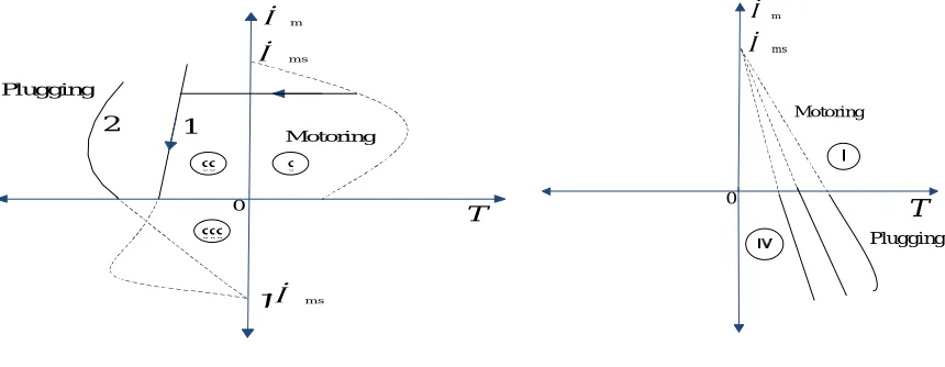
When phase sequence of supply of the motor running at a speed is reversed by interchanging connections of any two phases of the stator with respect to supply terminals and thus operation shifts from motoring to plugging as shown in
Fig. 1Plugging characteristics are actually extension of motoring characteristics for negative phase sequence reverse the direction of rotating field [6]. If the slip for plugging is denoted by then:
0 T Motoring m s m Plugging
Fig. 1 1 : Natural Characteristics Fig. 2 Plugging in IV quadrant with large
2: With external resistance in rotor resistance in rotor
Motor performance can be calculated from the equations given below:
=
+
(2)
=
( )
(3)
Using equations (1) and (2) we get the below relation:
=
+
(4)
Where and are the stator and rotor currents respectively in motoring mode of induction motor.
Stator current for braking mode is obtained by replacing the slip( )by (2− ). Hence plugging mode current is given by:
.
=
+
( )(5)
Reference to equations (4) and (5) the following relation is obtained:
.
>
(6) In case of the wound rotor motors a resistance equal to the starter resistance is inserted in the rotor to limit the braking current to the starting value. This also increases the braking torque as shown by the curve 2 of the Fig. 1 and torque is not zero at the zero speed. When used for stopping motor it is necessary that the motor should be disconnected from the supply at or near zero speed [7]. This makes it necessary to use an additional device for detecting the zero speed and disconnecting the motor from the supply. This type of braking is suitable for reversing the motor. As the motor is already connected for operation in the reverse direction and torque is not zero at zero speed, motor smoothly decelerates and then accelerates in the reverse direction [8].A special case of plugging occurs when an induction motor connected to positive sequence voltage is driven by an active load in the reverse direction (quadrant IV). Crane hoist is one such application. A large rotor resistance is employed so that the characteristics have a negative slope and thus drive is state stable as shown in above Fig. 2.In this method mechanical energy supplied to rotor either by active load or from kinetic energy stored in motor and load inertia is converted into electrical energy and wasted in rotor resistance. Additional energy is taken from the source and wasted in rotor resistance [9]. When braked under no load from synchronous speed total amount of energy
dissipated in rotor resistance is given by 3 2 ,which is three times of the energy stored in inertia [10]. Thus an additional energy equal to is taken from the source.
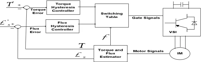
IV. CLASSICAL DIRECT TORQUE CONTROL STRATEGY
The basic concept of direct torque control is to directly select stator voltage vectors according to the torque and flux errors which are the differences between the references of torque and stator flux linkage and their actual values. The governing equation for torque for this scheme is due to the interaction of stator and rotor fields [11].
*
S
*
T
T S
Fig. 3 Block diagram of classical direct torque control
Torque and stator flux linkage are computed from measured motor terminal quantities i.e. stator voltages and current [12]. An optimal voltage vector for the switching of VSI is selected among the six nonzero voltage vectors and two zero voltage vectors by the hysteresis control of stator flux and torque.
A. FLUX AND TORQUE CALCULATION
This is the simplest method of stator flux estimation, where the machine terminal voltages and currents are sensed and from the stationary frame equivalent circuit the fluxes are estimated as below relations.
= (7) = −
√ ( + 2 ) (8)
= (9) = −
√ ( + 2 ) (10)
= ∫( − ) (11) = ∫ − (12)
The magnitude of stator flux is calculated by:
= ( + ( (13)
Torque is calculated as per below relation:
= − (14)
B. TORQUE AND FLUX CONTROLLER
Outputs of flux controllers are as per below conditions
= 1 for > + (15)
=−1 <−
Where 2 is hysteresis bandwidth of the flux controllers.
Outputs of torque controllers are as per below conditions
= 1 > +
=−1 <−
= 0 − < < +
C. SWITCHING SELECTION
Switching selection is based on values of , and S(K)and voltage vectors are selection for inverter switching is done as per below table 1.
Table.1 Applied selected voltage vector to inverter
S(1) S(2) S(3) S(4) S(5) S(6)
1 1 0
-1
-1 1
0 -1
V. PROPOSED CONSTANT SWITCHING FREQUENCY STRATEGYTODTCIMDRIVES
*
S
*
T
T
S
e
-jθ * V s* Vqs
* Vds
* V s
Fig. 4 Block diagram of proposed DTC strategy to induction motor drive
The torque ripple generates noise and vibrations, causes errors in sensor less motor drives. The reason of the high current and torque ripple in classical direct torque control is the presence of hysteresis comparators together the limited number of available voltage vectors and variable switching frequency. To minimize the torque ripple of induction motor drives a constant switching frequency approach based on space vector modulation technique is used [18]-[21]. Space vector modulation technique is accomplished by rotating a reference vector around the state diagram which is composed of six basic non-zero vectors forming a hexagon. A circle can be inscribed inside the state map and corresponds to sinusoidal operation. The area inside the inscribed circle is called the linear modulation region or under-modulation region. In the above figure the basic space vector under-modulation strategy is shown for induction motor drive. It consists the PI speed, PI torque and PI flux controller. Here PI controllers are used for steady state error reduction [22]. Reference to Fig.4 ∗ and ∗
are used as command or desired speed and flux respectively. Electromagnetic torque, and flux are calculated in the same way as in classical direct torque control strategy [23].
A. IMPLEMENTATION PROCEDURE OF A TWO-LEVEL SPACE VECTOR MODULATION STRATEGY FOR INDUCTION MOTOR DRIVES
The procedure for implementing a two-level space vector PWM can be summarized as follows: 1. Transform three phase quantities to two phase quantities: ABC to dq.
2.
Calculate the phase angle and reference voltage vector=
(
+
)
(20)
The phase angle is calculated as below:
=
(21)
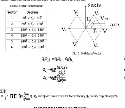
3. Find the sector in which lies, and the adjacent space vectors of V k and V k+1 based on the sector angle.(Where K = 1,2,……….5)
Sector varies with variation of the angle ( )as per Table 2 given below:
a x is
a x is
1
V
2V
3V
4
V
5
V
V
61
T
2T
V
refFig. 5 Switching Vector
=
+
(22)
=
( )( )
(23)
=
( )(24)
ℎ
=
=
1, 2 and are dwell times for the vectors , and respectively [24].VI. SIMULINKMODELSANDRESULTS
A. SIMULINK MODELS OF CLASSICAL AND PROPOSED DTC STRATEGY
Simulink models are created as per following induction motor parameters:
Nominal Power = 150 KW, Rated Torque = 955 N-m, Stator voltage = 460 V, Frequency = 50 HZ
Stator Resistance = 14.85 mΩ,Stator Self Inductance = 0.3027 mH,Rotor Resistance = 9.295 mΩ
Rotor Self Inductance = 0.3027 mH, Mutual Inductance = 10.46 mH
The below figures shows the simulink model of classical and space vector modulation direct torque control strategies. Table 2 Sector Identification
Sector
Degrees
1 0 < ≤60
2 60 < ≤120
3 120 < ≤180
4 180 < ≤240
5 240 < ≤300
Fig. 6 Simulink model of Classical DTC Fig. 7 Simulink model of Proposed DTC
The simulation of the classical and proposed DTC is done in the discrete methodology. In classical DTC inverter switching pluses are obtained from switching table and the hysteresis controllers logics. Flux and torque both are estimated using the motor parameters i.e. stator voltages and currents.
A. SIMULATION RESULTS
Classical DTC Proposed DTC
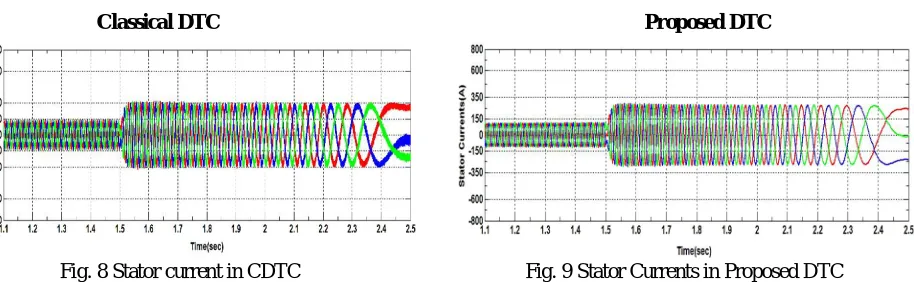
Fig. 8 Stator current in CDTC Fig. 9 Stator Currents in Proposed DTC
Reference to Fig.8 and Fig.9 plugging mode(1.5 to 2.5 second) current is more than the motoring mode(from 1.1 to 1.5 second) current, It occurs due to increased slip in the plugging mode. Currents in the proposed DTC is much smooth as compared to classical DTC.
When the motor is needed to be stopped, it should be disconnected from the supply at near zero speed axis. The motor is connected to rotate in the reverse direction, speed reversal occurs after crossing the zero speed axis.
Fig. 12Torque in CDTC Fig. 13 Torque in Proposed DTC
As shown above in Fig.12 torque settling time is 0.04 sec. and Torque upper deviation is -530 N-m and lower deviation is -640 N-m and average torque is -585 N-m.
Peak to peak Torque ripple =|(−530)−(−640)| = 110 N-m (25)
As shown above in Fig.13 torque settling time is 0.05 sec. and Torque upper deviation is -580 N-m and lower deviation is -610 N-m and average torque is -590 N-m.
Peak to peak Torque ripple =|(−580)−(−610)|= 30 N-m (26)
Reference to Fig. 10, Fig. 11, Fig. 12 and Fig. 13 the below discussions are done:
Between time t = 1.1 to 1.5 sec.
Speed> 0 PowerFlow= Torque×Speed
(27)
Torque> 0 PowerFlow > 0
Hence in this region power flow is positive and flowing from source to load, which is required condition for first quadrant operation. So drive is operating in first quadrant and in as forward motoring mode.
In time range t = 1.5 to 2.5 sec.
Speed> 0 PowerFlow= Torque×Speed
(28)
Torque< 0 PowerFlow < 0
Fig. 14 Stator flux trjectory of classical DTC Fig. 15 Stator flux trjectory of Proposed DTC
In the Fig. 14 and Fig. 15 stator flux trajectories of classical and proposed DTC strategies are shown respectively. Here we can observed that flux ripple is reduced in space vector modulation DTC is reduced as compared to classical DTC.
VII. CONCLUSIONS
In this paper drive plugging mode operation of induction motor for stopping and speed reversal is presented. The simulink results verifies the statements for plugging operation. Classical DTC control strategy is modified in order to improve the performance of an induction motor drive in terms of torque, flux and current ripple. Induction motor drive operation under the proposed direct torque control strategy gives reduced torque and flux ripple as compared to classical DTC for the entire load and speed operation. The reason of reduced torque ripple in proposed DTC is constant switching frequency of inverter. The fast dynamic response and robustness merits of the classical direct torque control strategy are entirely preserved. This is due to less settling time of classical direct torque control strategy as compared to proposed DTC strategy. Settling time depends on the total computations required for any strategy. Computations required in classical DTC is less as compared to proposed DTC.
REFERENCES
[1] G.K Dubey “Fundamentals of electrical drives” Narosa Publishing House Second Edition 2001 Fifty Eight Reprint 2014. [2] B.K.Bose, “Modern Power Electronicsand AC Drives” Prentice-Hall, 2005.
[3] Ion Boldea, Cristian Lascu and Frede Blaabjerg“A modified direct torque control for induction motor sensorless drive”IEEE Transactions On Industry Applications, vol. 36, no. 1, January/February 2000.
[4] G. Escobar, A. M. Stankovic´, E. Galvan, J. M. Carrasco, and R. Ortega “A family of switching control strategies for the reduction of torque ripple in dtc”IEEE Transactions On Control Systems Technology, vol. 11, no. 6, November 2003.
[5] JoonHyoung Ryu, Kwang Won Lee, and Ja Sung Lee “A unified flux and torque control method”IEEE Transactions on Power Electronics, vol. 21, no. 1, January 2006.
[6] Zhifeng Zhang, Renyuan Tang, Baodong Bai and DexinXie “Novel direct torque control based on space vector modulation with adaptive stator flux observer for induction motors.IEEE Transactions On Magnetics, vol. 46, no. 8, August 2010.
[7] Giovanni Serra, Domenico Casadei, Angelo Tani, Luca Zarri, and Francesco Profumo “Performance analysis of a speed-sensorless induction motor drive based on a constant-switching-frequency dtcscheme”IEEE Transactions On Industry Applications, vol. 39, no. 2, March/April 2003.
[8] Yen-Shin Lai,Jian-Ho Chen “A new approach to direct torque control ofinduction motor drives for constant inverter switching frequency and torque ripple reduction”IEEE Transactions On Energy Conversion,vol.16,no.3,September 2001.
[9] Kyo-Beum Lee, Joong-Ho Song, and Ji-Yoon Yoo “Torque ripple reduction in dtc of induction motor driven by three-level inverter with low switching frequency”IEEE Transactions On Power Electronics, vol. 17, no. 2, March 2002.
[10] R.Krishnan.’Electricmotor drives modeling, analysis and control’,Prentice- Hall,2001.
[11] Keliang Zhou and Danwei Wang“Relationship between space-vector modulation and three-phase carrier-based pwm: a comprehensive analysis”IEEE Transactions On Industrial Electronics, vol. 49, no. 1, February 2002.
[12] M. A. Jabbar, Ashwin M. Khambadkoneand Zhang Yanfeng “Space-vector modulation in a two-phase inductionmotor drive for constant-power operation”IEEE Transactions On Industrial Electronics, vol. 51, no. 5, October 2004.
[14] Sung-Hoe Huh,Kyo-Beum Lee,Ji-Yoon Yoo and Frede Blaabjerg“Performance improvement of dtc for inductionmotor-fed by three-level inverter with anuncertainty observer using rbfn”IEEE Transactions On Energy Conversion,vol.20, no.2,June 2005.
[15] Giuseppe S. Bujaand Marian P. Kazmierkowski“Direct torque control of pwm inverter-fed ac motors—a survey”IEEETransactions On Industrial Electronics, vol. 51, no. 4,August 2004.
[16] Tole Sutikno “An optimized switching strategy for quick dynamic torque control in dtc-hysteresis based induction machines” IEEE Transactions On Industrial Electronics,vol. 58, no. 8, August 2011.
[17] G. Narayanan and V.T. Ranganathan “Aalyticalevoluation of harmonic distortion in pwm ac drives using the notion of stator flux ripple” IEEE Transation On Power Electronicsvol. 20(2), pp. 466-474, Mar. 2005.
[18] Paul C. Krause, Oleg Wasynczuk and Scott D. Sudhoff “Analysis of Electrical machinery and drive systems second edition IEEE. [19] Austin Hughes “Electric motors and drives” Fundamentals, types and applications Third Edition 2006 Elsevier Ltd.
[20] Peter Vas “Sensorless vector and direct torque control” Oxford Science Publication.
[21] VanjaAmbrozic, ManueleBertoluzzo, Giuseppe S. Buja, and Roberto Menis,”An assessment of the inverter switching characteristics in dtc induction motor drives”IEEE Transactions On Power Electronics, vol. 20, no. 2, March 2005.
[22] Francesco Profumo“FOC and DTC: Two viable schemes for inductionnmotors torque control”IEEE Transactions On Power Electronics, vol. 17, no. 5, September 2002.
[23] Arash Kiyoumarsi, Mohammad Hossein Vafaie, Behzad Mirzaeian Dehkordi and PaymanMoallem, “Minimizing torque and flux ripples andimproving dynamic response of pmsm usinga voltage vector with optimal parameters”IEEE Transactions On Industrial Electronics, vol. 63, no. 6, June 2006.
[24] Thomas G. Habetler, Francesco Profumo, Michele Pastorelli, and Leon M. Tolbert, “Direct torque control of induction machines using space vector modulation”IEEE Transactions OnIndustry Applications, vol. 28, no. 5, September / October 1992.
BIOGRAPHY
Pradeep Kumar Yadav was born in Faizabad, India in 1991. He completed his B.Tech. degree in electrical and electronics engineering from BBDNIIT Lucknow, M.Tech. degree in electrical engineering with specialization in power electronics and drives from Kamla Nehru Institute of Technology Sultanpur, affiliated to Dr. A. P. J. Abdul Kalam Technical University, Lucknow, Uttar Pradesh India.