Localization of on Road System in VANET
using Grid Patterns
Sreedevi1, Dr. Sumalatha2
P.G. Student, Dept. of ECE, JNTUA Engineering College, Andhra Pradesh, India1
Head of the Department, Dept. of ECE, JNTUA Engineering College, Andhra Pradesh, India2
ABSTRACT:Our main objective is to finda way out to the inexact positioning in GPS handsets due to signal losing
GPS locators. Currently GPS navigators are in widespread use by drivers for navigation. People are depending more and more on GPS progressively, and many of them has just stopped checking and printing maps before they depart from home with full confidence and trusting GPS. However, as GPS signals are sensible to terrain, vehicles cannot get their accurate locations. To address this issue, we put forward an ovel On-road localization in VANET with G3 pattern, in which vehicles can self- organize themselves into a VANET and they can exchange location and distance information and coordinates with each other to find out an appropriate position for all the vehicles inside the network even without GPS .
KEYWORDS:GPS, RSU, VANET, Localization, G3.
I. INTRODUCTION
Vehicular ad-hoc network (VANET) is a form of mobile ad hoc network which provides communication amongst nearby vehicles and deliver interesting roadside services which includes vehicular safety, averting traffic congestion, providing alternate routes, calculating approximate time to reach destination. Every vehicle in VANET is furnished with a wireless on-board unit (OBU) which allows a vehicle to communicate with other vehicles or with road side units (RSUs) through short-range wireless communication.
VANET is having two modes of communication 1. Vehicle-to-Vehicle (V2V) among vehicles
2. Vehicle-to-Infrastructure (V2I), between vehicles and Road-Side Units (RSUs).
Vehicle to vehicle communication is good for short range vehicular systems. It is speedy and provides great reliability and hence ensures road safety. It does not bother about the road side infrastructure. V2V does not suffer from the issue of vehicle shadowing which means a vehicle in small size is shadowed by a vehicle in large size and hence eliminates its need to communicate with the infrastructure on road side.
Vehicle to infrastructure gives solution for long range vehicular systems. It utilizes prior network frameworks which includes wireless access points such as road side units.
Localization in a VANET is necessary for the cooperative interchange of information. The main feature of road safety in a VANET is to estimate the location of every individual vehicle within the network and ensuring that their location is not causing any hazard to other vehicles in the network. Accurate localization helps to find out dangerous road situations in prior and can ensure road safety .But because of the sensibility of GPS signals to terrain, we are not able to get correct location. To address this issue, we propose novel On-road localization in vanet with G3 pattern, in which vehicles can self- organize them into a VANET and they can exchange location and distance information and coordinates with each other to find out an appropriate position for all the vehicles inside the network even without GPS.
II. RELATEDWORK
Localization schemes are widely divided into two type’s namely non collaborative localization and collaborative localization. In non-collaborative localization, the position of the node is calculated from its own information using specifically furnished hardware such as camera and laser which is not in our assumption. In collaborative localization the position of the node is calculated with the help of other nodes. Collaborative localization is again categorized into two types namely range based approach and range free approach. In range based approach, different techniques named as time of arrival, signal attenuation and time difference of arrival are used to calculate distance between some of the nodes. Then position of other nodes is calculated using the geometric relationship obtained from position aware nodes by using a system of equations. This technique introduces huge error propagation because this technique need interchange of messages frequently which introduces large overheads and in some cases it needs extra resources. In this paper we are not assuming the availability of any such resources like road side stations.Range free approach is most widely used in sensor networks and in this approach measuring of distance is not required. Alternatively, in this method a node uses the position of many beacon nodes to find a small region of its possible residence. In this approach, accuracy of calculated location improves greatly by taking into account, the topology of the network. The common need of the range free approach is to have a huge number of position aware nodes and hence it cannot be used in VANET.
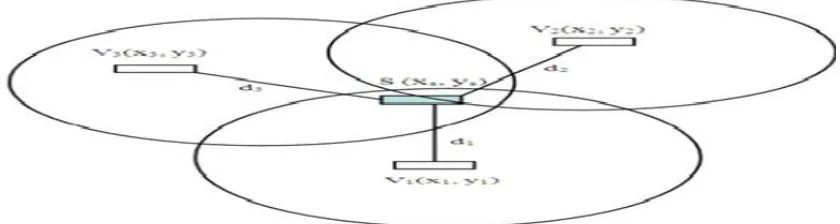
III.GENERAL IDEA OF G3PATTERN
A vehicle calculates its position and its distance with other vehicles in its surroundings through periodic interchange of beacon messages. A threshold for acceptable distance is set and only distances which are less than this threshold are taken into account and hence location is estimated accurately. If the calculated distance is greater than the estimated communication threshold then that distance information is not taken into account. In order to calculate the unknown position of a node just by having the known positions of its neighbouring nodes and the distances to them we must have a minimum of three location aware neighbouring nodes. This geometric relation between a vehicle with unknown location and its three neighbourhood vehicles with known positions is known as G3 pattern. More and more complicated mathematic equations based on the position information about the neighbour’sneighbour can be divided into patterns like G2-2, G2-1, and G3 and hence unknown position of a node is calculated in an iterative manner. By using the iterative calculations errors grow exponentially and hence we propose a grid based technique that uses only addition operations and thereby errors are forwarded only linearly. Moreover using grid based technique to calculate the location has an advantage of light overhead and it is also best suitable for real time on road location calculation. This grid method also gives a unique location for a node in a selected geometric region. When the vehicles in a road network are less, it is difficult for a position unaware vehicle to find 3 neighbours and hence this position unaware vehicle incorporates multihop way method to calculate the location. By this multihop way more than one possible position for a node is calculated by some fuzzy patterns. By establishing pre-determined parameters and checking whether the conditions are met, a unique position for a node is calculated.
IV.SYSTEM OVERVIEW
The vehicular networking topology has a unique characteristic that the vehicles in the network stay in lines because vehicles move in a straight line on roads. This makes it impossible to calculate the location of a vehicle in G3 pattern. In such cases we pick two nodes from the three location aware nodes. Then we calculate the distances to determine the location. However this introduces error.
In on road localization with grid system, vehicles in the network have two modes namely the tunnel mode and the city mode. In the tunnel mode, most of the vehicles on the road network are unaware of their location and the communication protocol used by them would be announcement centric. For instance, when the vehicles inside a tunnel are unaware of their locations, they patiently wait for the position and the distance information to be forwarded hop by hop from location aware vehicles which are outside the tunnel. In the city mode, most of the vehicles in the network are aware of their locations and hence request centric protocol is used i.e., when a vehicle in city mode is unaware of its location it sends a request to the other location aware vehicles.
Generally a vehicle in a network will choose among the two modes based on the preloaded map. For instance, when a vehicle is moving close to a tunnel following the map directions guided by the GPS, then the vehicle will choose tunnel mode automatically. But in some situations, the best mode cannot be selected by the vehicles specifically when the GPS is just switched on and there is no sufficient location information from the GPS satellites.
The reactive routing protocol establishes a route to a defined destination if and only if it is needed on demand. AODV is the most commonly used reactive routing protocol .AODV stands for adhoc on demand distance vector. It is a routing protocol developed by enhancing the properties of DSDV. In order to discover a route in AODV two packets are involved namely route request (RREQ) and route reply (RREP) packets. A route request packet is generated by the source node and is sent to all the neighbours till it encounters the destination node. When an intermediate node receives RREQ packet it produces a RREP containing the number of hops it needed to reach to the destination node. Every intermediate node which is participating in giving reply to the source node produces a forward route to the destination node. As the routes are established only on demand, the AODV routing protocol uses minimum number of packets in order to discover the route.
V. SIMULATION
a vehicle. Second reason is measuring the sensitivity of grid based system to the error in distance measurement. Third reason is finding out the impact of various system parameters on the performance of our proposed model. Error in calculating the location and localization delay are two important factors to estimate the performance of our system. Localization delay is the delay between the time a node sends a request to its neighbors and the time it calculates its location.
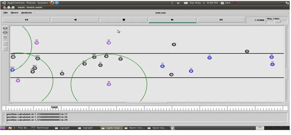
Figure 3: Network Animator Window
In fig3 we have shown the output traced on NAM. NAM stands for Network Animator .This NAM upon receiving the input file having the packet transmission events, draws the network events graphically. In this window we will show the animation of packet transfer, packet drops and mobility.
In fig4, we have shown the Xgraph of time versus overhead packets. With the help of Xgraph, results like packet delivery function, packet loss and delay can be shown as graphs. Our proposed model which is green curve has less overhead on an average when compared to previous model which is shown with red curve in fig4. In fig 5, we can see that our proposed model which is green curve has improved packet delivery function when compared to previous model.
VI.CONCLUSION
We have implemented on road localization in VANET with linear error propagation by using the grid3 pattern there by propagating the errors linearly instead of exponentially. By using geometric relations among vehicles and grid based patterns we are able to calculate the location of a vehicle accurately even in the absence of GPS.
REFERENCES
[1] S. Sesay, Z Yang and Jianhua He, "A survey on Mobile Ad Hoc Network", InformationTechnology Journal 3 (2), pp. 168-175, 2004 [2] Moustafa, H., Zhang.Y.” Vehicular networks: Techniques, Standards, and Applications”. CRCPress, (2009).
[3] Yaseer Toor et al., “Vehicle Ad Hoc Networks: Applications and Related Technical issues”, IEEECommunications surveys & Tutorials, 3rd quarter 2008, vol 10, No 3,pp. 74-88.
[4] Y.- C. Hu and K. Laberteaux, “Strong Security on a Budget,” Wksp. Embedded Security for Cars, Nov. 2006;
[5] Maxim Raya e al., “The Security of Vehicular Ad Hoc Networks”, SASN’05, Nov 7 2005, Alexandria, Virginia, USA, pp. 11-21 [6] Hannes Hartenstein et al., “A tutorial survey on vehicular Ad Hoc Networks” , IEEECommunication Magazine, June 2008, pp. 164-171 [7] Jose Maria de Fuentes, Ana Isabel Gonzalez-Tablas, and Arturo Ribagorda, "Overview of SecurityIssues in Vehicular Ad Hoc Networks",
Handbook of Research on Mobility and Computing, 2010.
[8] Murthy, C. S. R.,Manoj, B. S. Ad Hoc Wireless Networks: Architectures and Protocols.PEARSON,ISBN 81-317-0688-5, (2011).
[9] Dahill, B. N. Levine, E. Royer and Clay Shields, "A Secure Routing Protocol for Ad HocNetworks", Proceeding of IEEE ICNP 2002, pp 78-87, Nov 2002.
[10] Y. C. Hu, D. B. Johnson and A. Perrig, "SEAD: Secure efficient distance vector routing for mobileWireless ad hoc networks", Elsevier B. V. , pp 175-192, 2003.
[11] K.Golestan, S.Seifzadeh,M.Kamel,F.Karray,andF. Sattar,“Vehiclelocalization inVANETs usingdatafusion
andv2vcommunication,”in2012ACMDIVANet.
BIOGRPHY
Dr. Sumalatha is working as the professor and hod of ECE department in JNTU Anantapur. She has been in teaching industry for 16 years and active in research field from 12 years. Her research area includes wireless communications and networks.