DSTATCOM Performance for Voltage Sag,
Swell Mitigation
Rupali D. Burungale1, C. R. Lakade2
Student, G. H. Raisoni Institute of Engineering & Technology, Wagholi, Savitribai Phule Pune University, Pune,
India.1
Professor, G. H. Raisoni Institute of Engineering & Technology, Wagholi, Savitribai Phule Pune University, Pune,
India2
ABSTRACT: The main aim of this paper is to improve the power quality of grid. Modern industrial processes are mainly based on electronic devices and their controls are sensitive to the power quality problems such as voltage sag, voltage swell and harmonics. There are chances of failure or a miss-operation of end user equipments. Voltage sag is most important power quality problem that exit in power system. Distribution static compensator (DSTATCOM) is a promising device to provide not only for voltage sag mitigation but also solution for the voltage stabilization, harmonics, and flickers. DSTATCOM consist of capacitor, inverter models, PWM control strategy, transformer to match the inverter output to the line voltage. In this paper 6-pulse DSTATCOM configuration with IGBT is designed and simulation model is developed using MATLAB SIMULINK. A new PWM based control method has been used to allow the control of the power supplied to electrical devices.
KEYWORDS: DSTATCOM, voltage sag, VSI, controller.
I. INTRODUCTION
power factor and maximum voltage dip to be compensated. The maximum load on the grid is an important task for DSTATCOM operation and desired voltage sag compensation. This paper proposes DSTATCOM system designed to maintain a constant RMS voltage value across a sensitive load. It can mitigate voltage sag caused by three phase fault and single line to ground fault. There are various methods which have applied to mitigate voltage sags. The conventional methods are to mitigate voltage sags are use uninterruptible power supplies and capacitor bank. Due to high cost of these conventional devices, the power quality problems are not completely solved. The DSTATCOM has emerged as promising device to mitigate the power quality problems such as voltage sag, voltage swell, harmonics and flicker. DSTATCOM is a shunt connected device which has ability to control the magnitude and phase angle of voltage or current. Generally, the DSTATCOM configuration consists of a DC voltage source, inverter circuit, coupling transformer and control strategy. The VSC converts the dc voltage into the set of three phase ac output voltages. These voltages are in phase and coupled with transmission lines through the reactance of the coupling transformer [2]. The PWM based control method is used which requires RMS voltage measurements and no reactive power measurements are required.
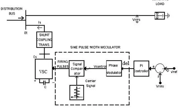
II. DSTATCOM CONFIGURATION
The DSTATCOM consist of dc voltage source, inverter circuit, coupling transformer and associated control strategy. The DSTATCOM is based on the voltage source converter (VSC) principle. The STATCOM is often used in the transmission system but when it is used in distribution system, it is called DSTATCOM. The DSTATCOM has quicker response time and compact structure as compare to the SVC. DSTATCOM is a shunt connected device which includes a voltage source converter (VSC) and dc capacitor, capable of generating and/or absorbing reactive power. The main block of the DSTATCOM is the voltage source inverter that converts dc voltage into the set of three phase output voltage at fundamental frequency.
Fig.1. Basic structure of DSTATCOM
The output terminals of the VSC are connected to the Point of Common Coupling (PCC) through an inductance, which could be a filter inductance of the coupling transformer, as shown in figure 1. DC capacitor is the input of voltage source converter (VSC), which carries the input ripple current of the converter and is the main reactive energy storage element. This capacitor could be charged by a battery source or by the converter itself. No reactive power is delivered to the system, if the output voltage of VSC is equal to the AC terminal voltage. If the output voltage of VSC is greater than the AC terminal voltage then DSTATCOM is in the capacitive mode of operation and vice versa. The D-STACOM employs an inverter to convert the DC voltage on the capacitor to a voltage source of adjustable magnitude and phase. The reactive power output of the D-STATCOM can be inductive or capacitive depending upon operation mode of the DSTATCOM [1]. The controller of the D-STATCOM is used to operate the inverter in such a way that the phase angle between the transmission line voltage and inverter voltage is dynamically adjusted so that the D-STATCOM absorbs or generates the desired VAR at the point of connection according to the requirement.
angle δ is used in the PWM generator as the phase angle of the sinusoidal control signal. The modulating angle δ is applied to the PWM generators in phase A and the angles of phases B and C are shifted 120 and 240 degrees, respectively.
Fig. 2. Control scheme designed for the DSTATCOM
III. VOLTAGE SOURCE CONVERTER(VSC)
Voltage source inverter (VSC) is a power electronic device which is connected in shunt or parallel to the system. VSC can generate a sinusoidal voltage of any required magnitude, frequency and phase angle. Voltage source converters are widely used in adjustable-speed drives, but it can also be used to mitigate voltage sags. The VSC is used to either completely replace the voltage or to inject the missing voltage. The missing voltage is the difference between the nominal voltage and the actual voltage. It also converts the DC voltage across storage devices into a set of three phase output voltages. The voltage source converter is normally based on some kind of energy storage, which will supply the converter with a DC voltage. The suitable adjustment of the magnitude and phase of the DSTATCOM output voltages allows effectives control of active and reactive power exchanges between DSTATCOM and AC transmission line. The semi conducting devises in the converter is then switched to get the desired output voltage.
IV. CONTROLLER
Fig.3 PI controller
Fig.4 Phase-Modulation of the control angle δ
Fig.5 Simulink Diagram of Controller
V. METHODOLOGY
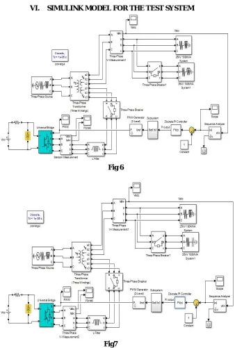
VI. SIMULINK MODEL FOR THE TEST SYSTEM
Fig 6
Fig7
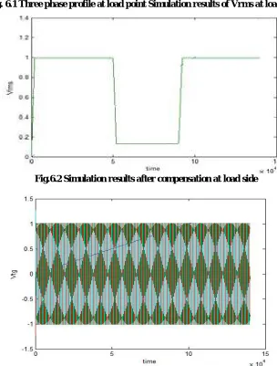
VII. SIMULATION RESULTS
Fig. 6.1 Three phase profile at load point Simulation results of Vrms at load point
Fig.6.2 Simulation results after compensation at load side
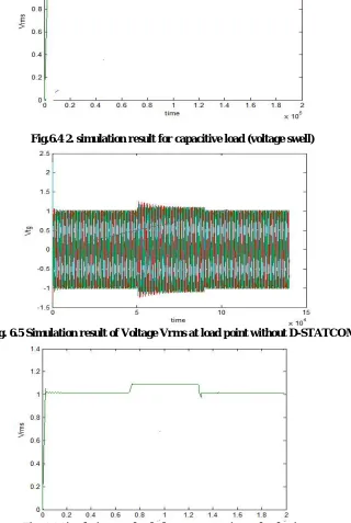
Fig.6.4 2. simulation result for capacitive load (voltage swell)
Fig. 6.5 Simulation result of Voltage Vrms at load point without D-STATCOM
Fig. 6.7 Simulation result of Voltage Vrms at load point with DSTATCOM
Fig. 6.8
VIII. CONCLUSION
This paper presents analysis and improvement of power quality (voltage sag, swell) performance of smart grid connected inverter used in distributed generation. From the above simulation results we can conclude that D-STATCOM is promising device and only the Vrms value is required to measure, so that complexity is reduced. DSTATCOM is used to mitigate the voltage sag, voltage swell at distribution side. It was observed that load voltage is very close to the reference value that is 1 pu and voltage sag and voltage swell are completely minimized.
IX. ACKNOWLEDGMENT
REFERENCES
[1] D.R.Patil & Komal K Madhale, “Design And Simulation Studies of Voltage Sag, Swell Mitigation” IRNet Transaction on Electrical and Electronics Engineering..
[2] Amin Nazarloo, Student Member, IEEE, Seyed Hossein Hosseini, Member, IEEE, Ebrahim Babaei, Member,IEEE, “Flexible DSTATCOM Performance as a Flexible Distributed Generation in Mitigating Faults” 2011 2nd Power Electronics, Drive Systems and Technologies Conference.
[3] N.Srinivasa Rao & H.J.Jayatheertha, “Modeling and Simulation of DSTATCOM for Power Quality Enhancement in Distribution System” International Journal of Engineering Research & Technology, ISSN:2278-0181, Vol.1 Issue 5, July- 2012.
[4] Simulation of DSTATCOM and DVR in power systems by S.V.Kumar and SIVA NAGARAJU J.N.T.U College of Engineering, Kakinada, A.P, India.