Negative Sequence Component:for Detection
of Inter-Turn Fault of Transformer
Rupali Chavhan1, DR. V. A. Kulkarni2
M. E Student, Department of Electrical, Government College of Engineering Aurangabad, Maharashtra, India1 Associate Professor, Department of Electrical, Government College of Engineering Aurangabad, Maharashtra, India2 ABSTRACT: In this paper, Negative Sequence Component scheme for analysis of inter-turn winding fault detection at initial level has been discussed. Inter-turn faults are the most difficult types of faults to detect within the power transformer. When small percent of turns are shorted, the sensitivity of current differential protection is limited so it does not cause false tripping due to normal imbalances in current.Digital relays are capable of computing the negative sequence current on both primary and secondary sides of the transformer along with the phase difference between these two negative sequence currents. Algorithm discussed is faster and more sensitive than conventional differential protection and capable of detecting inter-turn faults occurring during transformer energization. The mathematical analysis is illustrated and compared with simulation studies performed with MATLAB/ SIMULINK.
KEYWORDS: Inter-turn fault, negative sequence component, transformer protection.
NOMENCLATURE
c
r
- Core resistancen
r
- Number of resistanceT
r
-Total resistance of primary winding of transformerF
r
-Resistance of faulty turnsm
x
-Magnetizing reactancen
x
-Number of reactanceT
x
-Total reactance of primary winding of transformerinH
Z
-Input impedance of healthy transformerinF
Z
-Input impedance of faulty transformerF
x
-Leakage reactance of faulty turns'
F
x
-Leakage reactance of faulty turns referred to primary sidea – ratio of primary to faulty turns of transformer
1
N
- Primary turns of transformerf
N
Faulty turns of transformer ITF – Inter-turn faultI.INTRODUCTION
Transformer is a very vital part of the power system. It is a static device which works on the principle of mutual induction. In transformer whenever a fault occurs, electrical failure of transformer can be prevented by providing on-line condition monitoring. Generally, before occurrence of Turn-to-Turn (TTF) or inter-turn fault (ITF) in winding there is a development of aging-arcing. This process is known as incipient fault [1].
On histories of modern transformer breakdowns a brief analysis shows that near about 70-80% of failures are caused by inter-turn faults. There are various methods to spot turn-to-turn winding fault in transformer on the basis of terminal voltage and current. Such as V-I locus diagram, Dissolve Gas Analysis (DGA), Doernenburg Ratio Method (DRM), Frequency response Analysis (FRA), Reverse Voltage Measurement Technique (RVMT) ,on-load exciting current extended Park’s Vector, Leakage flux, Zero Sequence Component and Negative Sequence Component etc.[2].
The Negative Sequence Component is more sensitive to sense minor ITF and its action is based on evaluating the magnitude and phase of Negative Sequence Component like current, voltage and phase angle [3].
In detection of ITF in transformer with help of NSC of Current, the calculation of system has been prepared for different operating conditions, different number of shorted turns and different connection of power transformer. It observed that even when 2% of turns are shorted, the arrangement will work properly [4]. In fuzzy logic based protective relays an application to the power transformer protection indicates the sensitivity and selectivity of self-organized relay equating with traditional methodologies [5]. Under different functioning circumstances the identification of different types of current flowing in the power transformer by using simulation results offers fast, accurate and reliable experiences of WPT algorithm [6].
The behaviour of power transformer under occurrence of inrush current and ITF of transformer winding provides reliable protection, enhanced sensitivity for 3-phase fault detection [7]. Using new approach in [8] novel flux base protection is used for the protection of transformers to find turn to turn fault by inserting several Surge Coils on core legs in order to measure flux linkage at various stage. A Novel offline to online approach for TTF detection of the transformer indicates an increase in fundamental component of current due to fault which in turn, reduces a percentage contribution of individual harmonics [9].
II.PROTECTIVE RELAYING SCHEME FOR DETECTING TURN-TO-TURN FAULTS
Basically, a transformer ITF is functioned by conventional protection scheme. But the conventional protection scheme is bias and is not suitable for protection against ITF at incipient level. This drawback is excluded using upgraded protective relaying scheme by providing a way to confirm the presence of fault. Different method of negative sequence based relay operated area against CT saturation, magnetizing inrush etc. is implemented and all this is probable without addition of any cost as it is based on CT signals which are freely existing [10].
Fig.1. Turn-to-turn fault in primary side
A. Protection of transformer using negative sequence current
This relay makes use of negative sequence percentage differential current element which is calculated by vector sum of all current incoming the protection region. The condition for fault detection is that the magnitudes of phase comparison and the magnitude of primary and secondary negative sequence current must be larger than minimum rated current (Imin rated) [11].
B.Negative sequence component system
they require a different approach. Negative sequence network are basically equal to positive sequence network except for the absence of source and different phase shifts in some connection of the power transformer [12].
According to IEEE Standards at no load the transformer winding voltages be within 0.5% of the rated voltage. If a 0.5% imbalance is occurs in healthy system, it produces a negative-sequence voltage well below rated.
s V V
VRST negp negs
2
and
V
DIFF
V
negp
V
negs
s
(1)Where, S is transformation ratio
From equation (3) and (4) it is noticed that the primary and secondary negative sequence voltage gives restraining and differential voltage respectively. And both the primary and secondary side of NSC like current and voltage, transposed to the primary side of the transformer, which must be greater than 1% prescribed primary voltage. This prevents false tripping due to small imbalance occurs in healthy transformer. If differential current exceeds the restraining current equation a trip is assured. When transformer negative sequence current indicate that the transformer is being energized, negative sequence voltage are used to determine if transformer is experiencing a ITF or TTF [11], [13]. The following table I. gives technical specification of transformer which is require for simulation modeling.
TABLE I. TECHNICAL SPECIFICATIONS OF TRANSFORMER
Parameters Quantity
Capacity 100 MVA
Frequency 50 Hz
Voltage 132/66 kV
Connection
type Star - Star
Resistance R1=0.34848 Ω,R2=0.08712 Ω
Inductance L1 = 0.04437 H,L2 = 0.011092 H
Turns N1=100, N2= 50
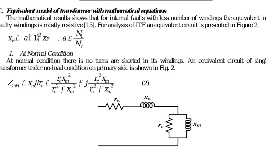
C. Equivalent model of transformer with mathematical equations
The mathematical results shows that for internal faults with less number of windings the equivalent impedance of faulty windings is mostly resistive [15]. For analysis of ITF an equivalent circuit is presented in Figure 2.
2 '1
FF
a
x
x
,f
N
N
a
1
1. At Normal Condition
At normal condition there is no turns are shorted in its windings. An equivalent circuit of single phase of transformer under no-load condition on primary side is shown in Fig. 2.
2 2
2
2 2
2
m c
m c m
c m c c m inH
x
r
x
r
j
x
r
x
r
llr
x
Z
(2)n n inH
r
jx
Z
Where,
n
r
2 22 m c m c
x
r
x
r
2 2m c m c m
x
r
x
r
x
, and
2 2 2 22 m c m c c m c m c n
x
r
x
r
r
x
r
x
r
x
(3)m c n n
x
r
r
x
(4)The angle of impedance can be calculated as follows:
m c n n inHx
r
r
x
Z
tan
1 (5)2. At Fault Condition
As shown in Fig.3 the input impedance can be calculated from the equivalent circuit. The actual value of resistance and leakage inductance of shorted turns is very low, especially for less number of faulty turns. Therefore, specifications referred to primary side determines the major part of input impedance of ITF of winding,
n n
f f
inF
r
jx
ll
r
jx
Z
Fig.3. Equivalent circuit of transformer when turn-to-turn fault to primary side
2 2
2 2 2 2 2 2 2 2 2 2 nF nF n F F n n F F n nF nF F n n F n F F n x r x x x x x r x r j x r r x r x r r r r s(6) F n nF
r
r
r
Andx
nF
x
n
x
F(7)
F F inFr
x
Z
tan
1 (8)The impedance angle depends on
r
Fandx
F. It is possible to find a method to detect ITF in transformer only when this dependency follows equation (11). As the number of faulted turns differs, the angle of input impedance also varies considerably.
Z
inFmust be smaller than
Z
inH. And this condition is satisfied by solving equation 8th
and 11th which is written in equation (12).
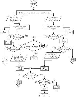
D. Turn-to-turn fault detection algorithm
Current and voltage existing on primary and secondary side of transformer is consider first in this system. As on the both sides of transformer detection of the magnitude of negative sequence current is above rated value, a phase comparison is warranted.
m c n n F Fx
r
r
x
r
x
(9)negative sequence current indicate that the transformer is being energized, negative sequence current or voltages are used to determine if the transformer is experiencing a ITF.
Inter-turn fault of a transformer by using sensitive technique, for one period the speed of algorithm is very fast and shall not be delayed for fault which coincides with inrush condition, but the operation is substantially delayed in case of second harmonic at period of second time [14].
negp
I
Vap,Vbp,Vcp
) , (Vas,Vbs Vcs
negp
V Vnegs
negp
I Inegs
negs
I
I
negpI
negs180
Fig.4 Flowchart of protective relaying scheme for detection of ITF
III.SIMULATION RESULTS
In this paper, the protective relaying scheme for ITF in winding of transformer using negative sequence component system is simulated in MATLAB/SIMULINK. Results are given for unprotected system and for protection using negative sequence component system due to occurrence of 2 %, 3%, 5%, and 10% of inter-turn fault respectively.
A. Unprotected system
B. Negative Sequence Protection
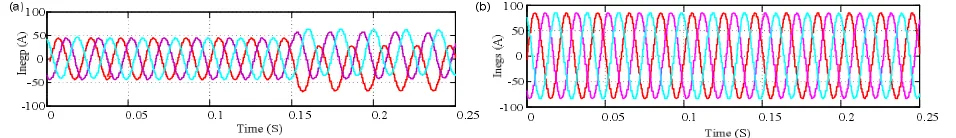
Fault is created and security of algorithm is tested. In fig.7 (a) significant change in primary negative sequence current takes place at 0.15 sec due 2 % of ITF inside the protected zone and fig. 7 (b) shows secondary Negative sequence current.
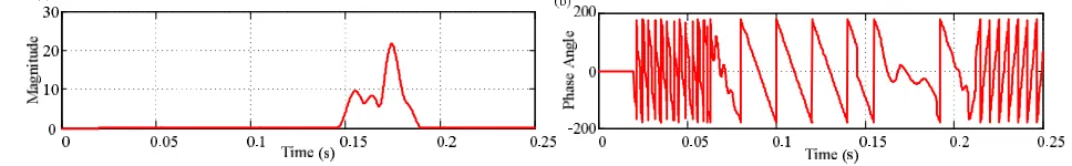
Fig. 8 (a) shows magnitude of comparison of primary and secondary negative sequence current and fig. (b)shows phase angle for difference between primary and secondary negative sequence current which is less than 1800.
Fig. 9 (a) and (b) gives simulation result for negative sequence current of primary and secondary winding for inter-turn fault of 3% at 0.145 sec.
Fig. 5 Waveforms of effect of ITF on inrush current with unprotected system for (a) phase A, (b) phase B, and (c) phase respectively
Fig.6Trip signal with unprotected system
Fig.7 Simulation result for 2 % Inter-turn fault, shows (a) Negative Sequence current of primary winding (b) Negative Sequence current of secondary winding
Fig. 8 Simulation results of 2% Inter-turn fault for Difference between primary and secondary negative sequence current of (a) Magnitude (b) phase angle
Fig 10 (a), and (b) shows magnitude and phase angle between primary and secondary negative sequence currentfor 3 % of ITF respectively.
Fig.11 (a) and (b) gives simulation result for negative sequence current of primary and secondary winding respectively at 0.125 sec. for 5 % of IFT.
Fig. 12 (a) and (b) showsmagnitude and phase angle between primary and secondary negative sequence current for 5 % of ITF respectively.
Fig.13 (a) and (b) gives simulation result for negative sequence current of primary and secondary winding respectively, for 10 % of IFT at 0.10 sec.
Fig.10 Simulation results of 3% Inter-turn fault for Difference between primary and secondary negative sequence current of (a) magnitude (b)phase angle
Fig.11 For 5 % Inter-turn fault, simulated result shows (a) Negative Sequence current of primary winding (b) Negative Sequence current of secondary winding
Fig. 12 Simulation results of 5% Inter-turn fault for Difference between primary and secondary negative sequence current of (a) Magnitude (b) phase angle
Fig 14 (a) shows magnitude and phase angle between primary and secondary negative sequence current for 10% of ITF.
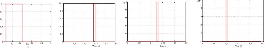
For 2% of IFT Fig. 15 (a) shows that a trip signal is received at 0.15 sec and the fault is analyzed up to 0.2. For 3% of IFT, fault is analyzed from 0.145 sec to 0.156 sec in Fig.15 (b). For 5% of IFT Fig. 15(c) a trip signal received at 0.125 sec and fault is analyzed up to 0.130 sec. For 10% of IFT fault is sensed at 0.1 sec and analyzed up to 0.132 sec as shown in fig. 15 (d).
TABLE II. COMPARISION OF MATHEMATICAL ANALYSIS AND SIMULATION RESULTS
IV. CONCLUSION
Simulation results for different percentages of Inter-turn Fault are discussed in this paper. It is observed that, IFT fault for various percentages as 2 % IFT, 3 % ITF, 5 % IFT, and 10 % IFT are represented and discussed in detail. The results are satisfactory for all cases. Using Negative Sequence Component, the value of current and phase angle is obtained to identify ITF on related winding. The algorithm is given in which comparison of primary and secondary current with NSC trip signal is carried out. This relaying scheme i.e. NSC is stable and very sensitive to offer better fault detection capability and that too without any addition sensor requirement.
REFERENCES
[1] A. Ashrafian, M. Rostami, G. B. Gharephpetian, and S.S. Shafiee Bahnamiri, “Improving Transformer Protection by Detecting internal
Incipients Faults”, International Journal of Computer and Electrical Engineering, Vol. 4, No. 2, April 2012, pp. 196-201.
[2] N.C.Joshi, Y.R. Sood, R. K. Jarial, and Rakesh Thapliyal, “ Transformer Internal Winding Faults Dignosis Method : A Review”, MIT
International Journal of Electrical and Instrumentstion Engineering Vol. 2, No.2 Aug.2012,pp. (77-81)
[3] M. Mostafaei, and F Haghjoo, “Flux-based turn-to-tuurn protection for power transformer”,Teharan, Iran, IET Gener. Transm. Distrib.,2016, pp
1-10.
[4] M. Babiy, R. Gokaraju, and J. Garcia, “Turn-to-turn fault detection in transformers using negative sequence currents,” in Proc. IEEE Elect. Power Energy Conf., 2011, pp. 158–16.
% Turns Faulted
Mathematical Analysis Simulation Results
negs negp I
I
(A)
negs negp I
I
InegpInegs
(A)
negs negp I
I
2 % 6.25 179.8° 6.70 179.10°
3% 21.22 179.11° 21.6 179.82°
5% 25.54 176.83° 26.02 179.93°
10% 42.96 179.81° 45.25 179.30°
Fig. 14 Simulation results of 10% Inter-turn fault for Difference between primary and secondary negative sequence current of (a) Magnitude
[5] B. Kasztenny, E. Rosolowski, M. Saha, and B. Hillstrom, “A self-organizing fuzzy logic based protective relay-an application to power transformer protection,” IEEE Trans. Power Del., vol. 12, no. 3, pp. 1119–1127, Jul. 1997.
[6] S. A. Saleh and M. A. Rahman, “Modeling And Protection of A Three-Phase Power Transformer Using Wavelet Packet Transform,” IEEE
Trans. Power Del., vol. 20, no. 2, pp. 1273–1281, April. 2005
[7] X. Lin, J. Huang, L. Zeng, and Z. Bo, “Analysis of Elec Tromagnetic Transient and Adaptability Of Second–Harmonic Restraint Based Differential Protection of UHV Power Transformer,” IEEE Trans. Power Del., vol. 25, no. 4, pp. 2299–2307, OCT 2010.
[8] F. Hagjjoo, M. Mostafaei and M. Mohammadzadeh, “A Novel Flux Based Protection Scheme for Power Transformers,”Proceedings in 9th
Annual Conference of the IEEE, Amirkabir University of Technology, Tehran,Iran, January 14-15,2015.
[9] P. A. Venikar, M. S. Ballal, B. S. Umre, and H. Murlidhar Suryavanshi, “A Novel offline to online approach to Detect Transformer Inter-turn
Fault”, IEEE Trans. Power Del., vol. 31, no. 2, pp. 482–492, April 2016.
[10] P. Venikar, M. Ballal and B. Umre, “ Negative Sequence based Relay - Operated Area to Detect Transformer Inter-turn Fault,” in Industrial
Electronics Society, IECON 2014 - 40th Annual Conference of the IEEE, Oct 2014, pp. 749–754.
[11] D. Zacharias and R. Gokaraju, “Prototype of a Negative-Sequence Turn-to-Turn Fault Detection Scheme for Transformer,”IEEE Trans. Power
Del., vol. 31, no. 1, pp. 122–129, February 2016.
[12] WALTER A. ELMORE, “Protective Relaying Theory and Applications”, Second Edition, Revised and Expanded.
[13] P. Venikar, M. Ballal and B. Umre and H. Suryavanshi, “Symmetrical Component based Advanced Scheme for Detection of Incipient
Inter-turn Fault in Transformer,”Proceedings in International Conference on condition Assessment Techniques in Electrical System(CATCON),2015, pp. 127-132
[14] A. Wiszniewski, W. Rebizant, and L. Schiel, “Sensitive protection of power transformers for internal interturn faults,”in Proc. IEEE Power
Tech, Bucharest,Romania,Jul.28–2,2009,pp.1–6.
[15] N. Asadi and H. M. Kelk, “ Modeling, Analysis, and Detection of Internal Winding Faults in Power Transformers,”IEEE Trans. Power Del.,