ABSTRACT
BALASUBRAMANIAN, RAMRAJPRABU. A Scalable Architecture for SIP using
Content Addressable Networks. (Under the direction of Dr. Injong Rhee)
Session initiation protocol (SIP) provides call establishment functions for
VoIP including location resolution, authentication, signaling compression, and
billing. These functions, when combined with the text-based nature of the
protocol, are highly CPU-intensive under a peak load. Practical limitation on
the available CPU power of a single SIP server mandates that the SIP
infrastructure supporting these functions be distributed over multiple servers.
Existing approaches to this problem using multiple nodes for SIP processing
with a shared location database or a replicated location database to distribute
the load are unfortunately not scalable or fault-tolerant, incurring high
maintenance and update overheads or introducing a single point of failure.
This thesis presents a proof-of-concept design and analysis of a scalable,
robust architecture for SIP infrastructures using a content addressable network
(CAN) model, called CASIP (CAN-based SIP). The combination of CAN and
SIP is highly complementary. The performance study of CASIP using an
implementation using a real SIP stack and NS-2 simulations shows that the
lookup) load of the network over multiple nodes very effectively without
incurring much routing and maintenance overhead; with use of simple cache
schemes, CASIP can linearly add the number of servers in proportion to the
increase in the subscriber base. The study also indicates that CASIP keeps the
reconfiguration overhead minimal. Furthermore, the CASIP architecture
exhibits high availability: a CASIP network of 50 nodes recovers from a
server crash within 5 minutes, during which only 2% of call setup requests are
dropped. These features enable cost-effective, incremental deployment of SIP
A SCALABLE ARCHITECTURE FOR SIP USING
CONTENT ADDRESSABLE NETWORKS
BY
RAMRAJPRABU BALASUBRAMANIAN
A THESIS SUBMITTED IN PARTIAL FULFILLMENT OF THE REQUIREMENTS FOR THE DEGREE OF
MASTER OF SCIENCE
DEPARTMENT OF COMPUTER SCIENCE
NORTH CAROLINA STATE UNIVERSITY
MAY 2004
APPROVED BY
___________________________________ DR. INJONG RHEE
CHAIRPERSON OF THESIS COMMITTEE
___________________________________ DR. JAEWOO KANG
___________________________________ DR. KHALED HARFOUSH
BIOGRAPHY
Ramrajprabu Balasubramanian was born on May 17, 1979 in Madurai, India.
He received his Bachelor’s degree in Computer Science and Engineering from
the College of Engineering Guindy, Anna University, Chennai, India in the
summer of 2000. He works for Togabi Technologies Inc, San Diego,
California. He has also been a Masters student at the North Carolina State
ACKNOWLEDGMENT
The author wishes to express sincere appreciation to Dr. Injong Rhee for his
assistance in the preparation of this manuscript. In addition, special thanks to
Dr. Jaewoo Kang and Dr. Khaled Harfoush for their valuable suggestions and
helpful ideas during the course of this research. Thanks to my colleagues at
Togabi Technologies Inc. for providing the motivation and knowledge into
TABLE OF CONTENTS
Table of Figures………v
1. Introduction... 1
1.1 Motivation... 1
1.2 Organization of thesis ... 5
2. The Session Initiation Protocol... 7
2.1 Introduction ... 7
2.2 Capabilities of SIP ... 7
2.3 Components in SIP ... 7
2.4 SIP Server and Clients... 8
2.5 SIP Proxy servers... 8
2.6 SIP Registration... 9
2.7 Call Setup... 10
3. The SIP scalability problem and existing approaches ... 14
3.1 The Problem ... 14
3.2 Shared database approach... 15
3.3 Replicated database approach... 16
3.4 Static partitioning approach... 17
4. CASIP Design ... 19
4.1 Design goals ... 19
4.2 CASIP architecture and basic operations... 20
4.3 Routing SIP Requests... 21
4.4 Locating a CASIP Node... 23
4.5 Join and leave ... 24
4.6 Bootstrapping ... 29
4.7 Failover handling ... 29
4.8 Optimization... 31
5. Performance results ... 35
5.1 Experimental Setup... 35
5.2 Effect of CASIP on CPU load at each node... 37
5.3 Path length and call setup delays in CASIP ... 42
5.4 Reconfiguration overheads ... 45
5.5 Effects of a failed Node... 46
6. Conclusion and Future Enhancements ... 47
6.1 Conclusion... 47
6.2 Future Enhancements ... 48
TABLE OF FIGURES
Figure 1 SIP REGISTER request ...9
Figure 2 Response to a SIP REGISTER request...10
Figure 3 SIP Call Setup using Proxy...11
Figure 4 SIP call setup request (INVITE) ...12
Figure 5 Response to a SIP INVITE request ...13
Figure 6 Acknowledgement of receipt of response ...13
Figure 7 Shared database approach ...16
Figure 8 Replicated database approach ...17
Figure 9 CASIP architecture ...21
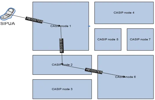
Figure 10 Routing REGISTER requests in CASIP...22
Figure 11 Routing call setup requests in CASIP ...23
Figure 12 New CASIP node sends JOIN request...25
Figure 13 CASIP network after addition of node 8 ...25
Figure 14 SIP JOIN Request...28
Figure 15 Response to SIP JOIN request...28
Figure 16 CASIP behavior during node failures...31
Figure 17 Topology used for simulation using NS-2 ...36
Figure 18 Load caused by SIP processing on each node...38
Figure 19 Load caused by local database operations ...39
Figure 20 Load caused by database operations performed over the network .40 Figure 21 Total load on the CPU at each node...41
Figure 22 Subscriber growth vs. number of nodes ...42
Figure 23 Average Path Length ...43
Figure 24 Call Setup delays in CASIP...44
Figure 25 Reconfiguration overheads in CASIP ...44
Figure 26 Node failure handling in CASIP...45
1. Introduction
1.1
Motivation
Session Initiation Protocol (SIP) [1] is a popular protocol for session establishment in
many Internet applications (e.g., push-to-talk [2], Internet telephony, presence [11] and
instant messaging [11]). SIP endpoints are known as SIP User Agents or SIP UAs. Each
UA acts as a User Agent Server (UAS) when it listens for incoming SIP requests and
also as a User Agent Client (UAC) when it originates SIP requests to another UA. SIP
client loosely denotes SIP end points where SIP UAs run, such as SIP phones and soft
phones. SIP (proxy) servers are intermediate network elements between the end points
and engage in the routing of SIP messages from one SIP UA to another UA based on a
logical SIP address. SIP servers also performs functions of authentication, authorization,
media trans-coding, signaling compression, and billing, and also acts as a gateway to
other types of telephony networks such as SS7. The SIP servers and SIP UAs in a
domain constitute a SIP Network. A logical SIP address (or SIP URI) consists of a
username and a domain that uniquely identifies a SIP UA. SIP UAs belonging to a
particular domain register their locations with the SIP Registrar of that domain by means
of a REGISTER request. The Registrar saves the location information of that particular UA in a location database associated with that domain. SIP servers of that domain refer
to that location database for address resolution between logical SIP URI destinations and
physical locations (or IP address and port pairs). A single domain ranges from several
thousands of subscribers to several hundreds of millions of subscribers. For example,
many wireless carriers are considering push-to-talk applications in their network. A
typical wireless carrier network has huge subscriber bases: currently, several US wireless
carriers have tens of millions of subscribers while several Chinese wireless carriers serve
A simple back-of-envelop calculation of loads can shed light on the scalability issues of
SIP based VoIP networks. Telephony networks are designed to sustain its performance
under the peak loads, typically with an arrival rate of 1-2 calls per hour per subscriber on
a busy occasion like Mother’s day. Each call consists of a call setup transaction and a call
tear down transaction, accounting for a total of 5 messages per call. Both setup and
teardown messages need to pass through the SIP infrastructure to enable generation of
accurate billing information Also SIP UAs register their location with the SIP Registrar
as frequently as once every 5 minutes. The IP addresses of clients are typically
dynamically assigned and abrupt IP address changes are common in the wireless Internet.
So this registration interval must be kept small so that the location information
maintained by the SIP network is consistent. This short re-registration period also
ensures that the presence and availability of that user be reflected among its friends very
quickly.
Based on the above figures, it can be estimated that the peak load caused by the SIP
registrations and call setups amounts to about 100,000 SIP messages per second (or
approximately 50,000 SIP transactions per second) for a 10 million subscriber base. Such
high call origination rates exact high load on SIP servers due to the inherent text based
nature of SIP. Commercially available SIP stacks can only process a maximum of a few
100 transactions per second on a single server node, thus requiring the SIP processing
load to be distributed over multiple nodes. Furthermore, the location updates cause about
30,000 updates per second to the location database for a 10 million subscriber base. This
update rate cannot be handled even with a completely memory resident database
(commercially available memory resident database can support up to only several
thousands of updates per second [3]). The capacity of the location database is often
restricted by the capacity of CPU and memory available in the location database server.
SIP vendors have attempted to increase the scalability of the SIP network by distributing
the SIP processing loads over multiple servers. However, as each server needs the
location service, the service is handled with either a shared location database [14, 15]
where a central location database server(s) handle all the location queries and updates, or
a replicated location database [16] where each database is replicated to multiple locations
to speed up the access. These approaches fail to address the problem adequately – the
replicated database approach does not solve the high update problem, as updates have to
be made to all servers for consistency, and the shared database approach introduces a
single point of failure. Even a hybrid version of these two approaches where database is
statically partitioned over multiple nodes is not easy to scale incrementally to the
growing population of subscribers.
This document presents a design and evaluation of a scalable, robust architecture for SIP
infrastructure using a Content Addressable Network (CAN) model [5]. In this
architecture, an overlay network of SIP servers forms a CAN network where SIP
messages are routed via distributed hash tables based on SIP addresses. Each SIP proxy
server is responsible for a unique sub-region of the hash space and maintains a separate
location database corresponding to its assigned region. Updates and lookups to the
location information of a user are handled by the SIP proxy server mapped to the region
that contains the hash value of the SIP address of the user. Each proxy server maintains a
small list of neighbors in the overlay network where a SIP message can be routed to
reach the final destination. Since each server maintains local state information about its
neighbors, a failure of a server does not affect the entire network. In addition, when a
server fails, its neighbors dynamically take over the hash space assigned to that failed
server and handle future requests to that space. Being based on content-addressable
networks this architecture is called CASIP (CAN-based SIP).
Scalability: The load balancing feature of CAN offers effective partitioning of the
location database over the multiple servers by allowing the SIP network to scale to very
large subscriber base. Thus, both lookup and update costs are distributed over the overlay
network of SIP servers.
High Availability: A carrier grade VoIP network requires extremely high reliability (i.e.,
five nine availability – 99.999%). CASIP provides a low cost solution for system
reliability by dynamically reconfiguring the overlay network at the face of server
failures, and a very high partial availability even during the time the failed node takes to
recover.
Low reconfiguration overheads: CASIP effectively localizes state updates caused by
node join, failure, and leave only to a small set of servers responsible for the hash space
where such changes are affected. This enables reconfiguring the network very easy and
cost effective to the operator.
These features allow incremental deployment of SIP servers. Network carriers require
cost effective solutions where the network infrastructures can be incrementally added in
response to the growing subscriber populations. They typically avoid too much up-front
investment only for anticipation of future growth.
The goal of this work is to demonstrate the feasibility of using CAN for solving the
scalability problem of SIP infrastructure. To accomplish this, a NS-2 simulation was
designed to quantify the performance of CASIP: load distribution, routing overheads, call
setup delays, failure recovery overhead, and node join and leave overhead.
The results of this research can be summarized as follows:
The routing overhead of CASIP linearly increases with the number of servers in the
simply caching techniques, the overhead is kept constant to two hops irrespective of the
number of servers. This is due to of the low churn rates in VoIP networks.
The number of CASIP servers required to handle a subscriber base of size one million is
around 13 (depending on the performance limit of memory-resident servers of today).
The minimal routing overhead allows this number to scale approximately linearly in
proportion to the number of subscribers. Thus, for example a 10 million user network
would require 130-150 server nodes.
The overhead of adding new servers is minimal: 15-20 messages per new node. This
indicates that CASIP can be incrementally deployed without much disruption in
on-going services.
The impact of server failure on the availability of the network is minimal: In a CASIP
network of 50 nodes, a single node failure drops only 2% of call setup requests for the
duration of five minutes before the network completely recovers from the failure. Given
the industry standard of the five nine availability which is equivalent to five minute
downtime (for each server) per year, CASIP still handles 98% of all the calls originated
during that five minute downtime of a server.
1.2
Organization of thesis
The balance of this thesis is organized as:
• Chapter 2 describes briefly the Session Initiation Protocol and the different
elements in a SIP infrastructure, and their interaction.
• Chapter 4 describes the CASIP architecture and the performance optimization strategies that can be used with it.
• Chapter 5 presents the results of a performance study of CASIP, and throws light
on the effectiveness of the proposed architecture over the other architectures
trying to solve the SIP scalability problem through analysis and data obtained
from simulations and experiments.
• Chapter 6 concludes with the effectiveness of the Content Addressable Network approach and its trade-offs, and the future enhancements and other potential
2. The Session Initiation Protocol
2.1
Introduction
SIP is a text based application-layer control protocol that can be used to establish,
maintain, and terminate calls between two or more endpoints, convey presence and
availability, do event notifications and instant messaging . SIP was developed within the
IETF MMUSIC (Multiparty Multimedia Session Control) working group, with work
proceeding since September 1999 in the IETF SIP working group. SIP is specified in
RFC 3261.
2.2
Capabilities of SIP
SIP provides the capability to determine the location of an endpoint using name to
address resolution. After resolving the SIP endpoint’s location SIP helps determine the
media capabilities of the endpoint to determine what media service to use in the call,
using the Session Description Protocol (SDP). SIP also helps provide meaningful
messages regarding the availability of an endpoint to answer calls. SIP establishes a
session once the call setup completes allowing further messages within the call to be
referenced using that session. SIP also provides a mechanism to handle termination of
calls and sessions created between the end points. Recently SIP also has been extended to
carry instant messaging traffic, and presence and availability notification using an
extension called SIMPLE [19].
2.3
Components in SIP
SIP is a peer-peer protocol. The end points of the call that act as peers are called as SIP
User Agents (UA). The UA can function as one of the following: UAC (User Agent
that acts as a server and listens for requests. The user agent is capable of functioning as
both an UAC as well as an UAS. The UA assumes one role based on the type of the
transaction (incoming request or outgoing request). If the UA initiated the request it acts
as an UAC and the terminating UA acts as an UAS.
2.4
SIP Server and Clients
From an architecture perspective the components of SIP can be grouped into two
categories: clients – the actual endpoints of the calls and servers that form the part of the
network side of SIP which aid the end points in call setup, through location resolution,
presence services, billing, network level authentication and authorization.
SIP clients include SIP phones, soft phones, gateways between SIP and other voice over
IP or conventional telephony networks. The SIP portion of the gateway behaves like a
SIP client with respect to the SIP network.
SIP servers include SIP proxies, SIP location Server (SIP Registrar), SIP redirect servers,
and SIP presence servers. SIP location servers store username to location mappings for
the user agents. SIP proxies are intermediate elements in a SIP network that receive
requests from a client and then forward it on the behalf of the client on to the server in
the work. Redirect servers supply the location information of a UA to anybody who
wishes to send requests to it, through SIP redirect messages. Presence servers act as
presence and availability accumulation functions, with which the UAs can subscribe for
presence and availability notifications of its contact list.
2.5
SIP Proxy servers
A proxy server receives messages from a client and forwards it to the server in the SIP
and provide the functionality such as authentication, authorization, Firewall & NAT
traversal, routing, network access control, and security. SIP proxies can be classified into
two categories, state-less SIP proxies and stateful SIP proxies. State less SIP proxies
forward messages based solely on the information available in that message, whereas
stateful SIP proxy creates a parallel transaction on the outgoing side for every incoming
transaction.
2.6
SIP Registration
A SIP user agent registers with a SIP Registrar server usually through a SIP proxy server,
by sending a REGISTER message. The REGISTER message contains the URI of the SIP UA and its location in the Contact field. The Registrar after authentication (optional)
adds an Address of record (AOR) for that SIP UA in its location database. Figure 1
shows a REGISTER request sent by a SIPUA to a SIP Registrar.
REGISTER sip: domain SIP/2.0 To: <sip:ua1@domain>
From: <sip:ua1@domain>; tag = zh234fasdfkjjlkj Via: SIP/2.0/UDP 10.1.1.200:5060
Contact: <sip:[email protected]:5060> Content-Length: 0
Figure 1 SIP REGISTER request
The Registrar inspects the ReqURI field and verifies that the REGISTER request is destined to the domain that it is responsible for storing location information. Then the
location information in the Contact header is used to create an AOR corresponding to the
logical SIPURI instead of an IP address and port pair, in which case that logical URI is
stored in the AOR created by the Registrar. Figure 2 shows the response generated by a
SIP Registrar server indicating a successful registration, to the SIP UA.
SIP/2.0 200 Ok
To: <sip:ua1@domain>
From: <sip:ua1@domain>; tag = zh234fasdfkjjlkj Via: SIP/2.0/UDP 10.1.1.200:5060
Contact: <sip:[email protected]:5060> Content-Length: 0
Figure 2 Response to a SIP REGISTER request
2.7
Call Setup
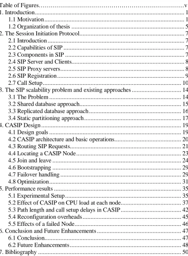
When a user agent UA1 wishes to establish a call with another UA2, UA1 creates a SIP
INVITE message destined to UA2 and sends it to its SIP Proxy; the SIP proxy then contacts the location server or SIP registrar in order to resolve the location of UA2. The
location service replies to the resolution request with the location of UA2. The proxy
then forwards the INVITE message to the location of UA2 as resolved by the location service. The INVITE request’s body usually contains an SDP message that contains the media capabilities of UA1. UA2 then responds to the INVITE with its media capabilities in the body. The call is then established when UA1 sends an ACK message back to UA2
indicating that it accepts the media capabilities supported by UA1. Then the media flows
Figure 3 SIP Call Setup using Proxy
Figure 3 shows the message flow during a SIP call setup using a SIP proxy from UA 1 to
UA 2. Figure 4 shows the SIP call setup request sent by UA 1 to the SIP proxy.
INVITE sip:ua2@domain SIP/2.0 To: <sip:ua2@domain>
From: <sip:ua1@domain>; tag = zh234fasdfkjjlkj Via: SIP/2.0/UDP 10.1.1.200:5060
Contact: <sip:[email protected]:5060> CSeq: 1234 INVITE
Call-ID: 100001 Content-Length: 239
Content-Type: application/sdp
v=0
o=user1 1234 1234 IN IP4 10.1.1.200 s=subject here
t=0 0
"$#!%&#'(
$%
*) +
,.-/$0!1 2)
)3+4 5687:9&;=<&>?@>A
B+C4 56D7E9&F;=<&3?@3AGIHJAK;LJH
M3+ N POQ68 RHRS,G-/0!1
T
c=IN IP4 10.1.1.200
m = audio 4322 RTP/AVP 0 1 3
Figure 4 SIP call setup request (INVITE)
The sip proxy queries the location database usually co-located with the Registrar for the
location of the SIP UA 2. The Registrar is also sometimes co-located with SIP proxies in
the case of small deployments. The location service responds with the location of SIPUA
2. The proxy then forwards the original INVITE to the UA 2, its address determined from the response from the location service. UA 2 responds to it with a 200 Ok response
express its willing to accept the call from UA1. A sample response generated by an UA
to an INVITE request is shown in Figure 5.
SIP/2.0 200 Ok
To: <sip:ua2@domain>;tag = zh912134244 From: <sip:ua1@domain>;tag = zh9234fasdfkjjlkj Via: SIP/2.0/UDP 10.1.1.200:5060
Via: SIP/2.0/UDP proxy.domain ; branch = zhg3423424 Contact: <sip:[email protected]:5060>
CSeq: 1234 INVITE Call-ID: 100001 Content-Length: 70 Max-Hops: 35
Server: vendor name/1.1 Content-Type: application/sdp
v=0
t=0 0
c=IN IP4 10.1.1.201
m=audio 4322 RTP/AVP 0 1 3
Figure 5 Response to a SIP INVITE request
SIP employs a three way handshake to negotiate call establishment, so the call originator
SIP UA1 acknowledges the response from UA2 using an ACK message as shown in Figure 6.
ACK sip:ua2@domain SIP/2.0
To: <sip:ua2@domain>; tag = zh12134244 From: <sip:ua1@domain>; tag = zh234fasdfkjjlkj Via: SIP/2.0/UDP 10.1.1.200:5060
Contact: <sip:[email protected]:5060> CSeq: 1234 ACK
Call-ID: 100001 Content-Length: 0
Figure 6 Acknowledgement of receipt of response
3. The SIP scalability problem and existing
approaches
3.1
The Problem
A SIP network designed to be able to handle a peak time load needs to be able to handle
about 10,000 SIP messages per second, for a subscriber base of about a million
subscribers. About one fourth of this SIP messages arise from SIP calls being made using
the logical URI as the destination. The SIP infrastructure helps resolve the destinations,
and forward the original SIP request to the resolved location. The SIP message which is
basically text based has to be parsed and formatted during call setup. The infrastructure
may also perform authenticate the caller, authorize the call, create billing records for the
call. In some networks such as wireless data networks where bandwidth is limited the
SIP message itself is compressed to save bandwidth (SIP messages are typically 500-800
bytes long, stateful compression can reduce this size to as low as 40-50bytes. With the
bandwidth of current wireless networks such as CDMA and GPRS being only in 10s of
kbps this reduction in message size translates to significant cut in the call setup time).
This causes additional computational requirement at the SIP infrastructure to compress
and decompress the SIP message used in communicating with the SIP UAs. Also when
looking up the destination SIP UAs location and while updating a SIPUA’s location in
the location database, resources at the SIP proxy are utilized. All these together make SIP
processing very hungry for CPU resources and exceed the limitations of the processing
power of a single SIP proxy element. Thus the only way for a SIP infrastructure to be
able to handle the load of several million subscribers is to distribute the SIP processing
In order to distribute the SIP message processing load on the SIP infrastructure the most
obvious idea would be to make the location server itself distributed. But still any SIP UA
should be reachable from any of these distributed SIP servers. That requires the
registration database to be available at all SIP server. That brings a huge impact on the
cost and design of the database because of the huge number of updates required every
time a UA updates its location information. There also exist problems of cache
consistency in the case of using a cache to speedup location lookups. One other concern
is about handling failures and failover mechanisms involved in these databases. All these
make the database design very complicated and make its cost become huge.
Several approaches have been taken by SIP infrastructure vendors to distribute SIP
scalability problems.
3.2
Shared database approach
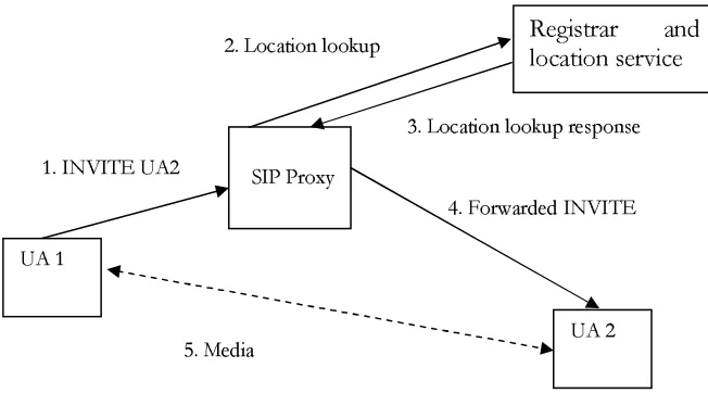
Distributed SIP proxies use a shared centralized location database (see Figure 7). In this
architecture, used in popular SIP Infrastructure vendors such as Ubiquity [14] and
Microsoft [15], the SIP processing load is shared among the SIP proxy nodes, but all
location lookup and update requests are handled by the shared database. Although use of
a centralized approach is acceptable to enterprises (due to their limited growth of the
number of SIP UAs served by the network), telephony providers refuse to deploy a
solution which is not geographically distributed. Natural calamities causing a failure to
the central office of the provider or network will leave the entire SIP network
unavailable. Also associated with this approach is the formatting and parsing of the
database requests for queries and updates to the location database, as messages
transmitted reliably over the network, there by adding additional load on the CPU
Figure 7 Shared database approach
3.3
Replicated database approach
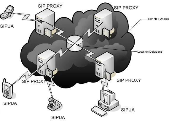
Distributed SIP proxies use a co-located replicated location database (see Figure 8).
Cisco SIP Proxy Server [16] uses this approach where a farm of Linux servers distributes
the SIP processing load and replicates the subscriber and location database using MySQL
on each node. This approach is clearly not scalable since all replicated databases must
handle the same number of updates. Even if a memory-resident database is used instead
of MySQL (disk-bound database system), update rates beyond several thousands per
second is hard to achieve. Since the whole database is replicated rather than distributed,
the capacity of each node is restricted by the CPU available to process the database
Figure 8 Replicated database approach
3.4
Static partitioning approach
Another approach is to partition the subscriber base into multiple segments and
distribute these segments over multiple nodes. Each segment can be updated
independently without any further interactions with other segments. Although this
architecture solves load distribution and failure locality, it incurs too much overhead for
reconfiguration and also operational costs for the telephony service provider. As new
nodes are added, the entire database must be reconfigured and reloaded, which could
cause unacceptable disruption of service. Also in the case of a node failure, nodes that
Taking into account the short comings of all the above approaches the content
addressable approach described in the following section, is designed to be easily
configurable, highly available, linearly scalable way of distributing SIP processing load
4. CASIP Design
4.1
Design goals
An ideal solution is a cost effective solution where new servers can be added to distribute
the location database load, without much reconfiguration overhead and disruption of
on-going services. The load distribution must be close to linear scalability where addition of
new nodes does not create much extra cost in serving the location lookups and updates.
Furthermore, network and server failures must be localized to the areas where the failures
occur (causing only those on-going call setups served by the failed components to be
disconnected), and should not impact future service requests. As long as future requests
are handled, temporary disconnection can be tolerable for some applications such as
push-to-talk. Also additional care is required to design any extensions required to SIP
transparent to the SIPUAs present in the network and restricted to only inside the SIP
infrastructure.
This section, describes a new architecture designed to meet the characteristics of the ideal
solution. This architecture is based on a structured P2P network, called content
addressable networks (CAN) [5]. This new architecture is called CAN-based SIP
(CASIP).
Our choice of CAN is only incidental and can be replaced by other structured P2P
networks such as Chord [7] and Pastry [8]. A structured P2P network was used as
opposed to unstructured ones such as Gnutella because they guarantee to serve a query as
long as the queried item is contained in the network. In a carrier-grade VoIP network,
this feature is essential. Furthermore, SIP networks are highly amenable for structured
P2P networks because the common disadvantages [4] of structured peer-to-peer (P2P)
networks typically experienced in a regular P2P application such as file or music sharing
transient environments and (2) inability to handle keyword based searches. However,
these disadvantages are not applicable for SIP networks because a carrier-grade VoIP
SIP network is a managed network. Thus, the churn rate due to node unavailability is
extremely low compared to a general file sharing P2P network where a node can be
frequently disconnected. Furthermore, since all SIP requests contain the exact SIP
address of SIP UAs, keyword based searches are not required.
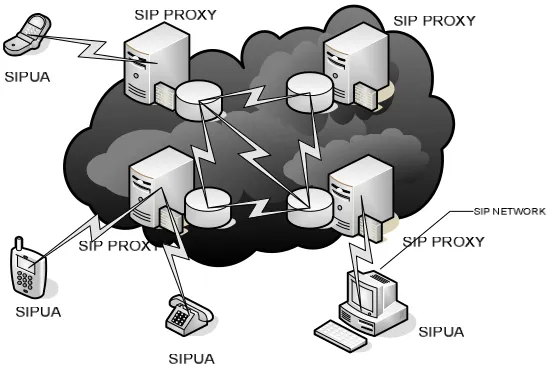
4.2
CASIP architecture and basic operations
In CASIP (as illustrated in Figure 9), the content is a (key, value) pair where key is a SIP
URI and value is the location information (e.g., IP addresses or telephone numbers) of
the SIP UA with that URI. For simplicity a 2-dimensional torus and a hash function H:k
(x,y) was chosen, where k is the SIP URI for a query and (x,y) is the Cartesian
coordinate of the location in the hash space for the content corresponding to key k (any
simple hash function that gives b bits as an output for H(k) can be split into b/2 bits for x
and the b/2 for y). The hash space is then divided into zones with a two dimensional
boundary. Each CASIP node is mapped to a unique zone and stores the location
information of SIP UAs whose SIP URIs are mapped to that zone by the hash function.
Each CASIP node “owns” the zone, stores the content database associated with the zone,
and performs CAN routing functions as well as the functions of a stateless SIP proxy
server. A uniformly partitioned d-dimensional torus contains 2d neighbors, but
depending on the order of partitioning, each node may have a varying number of
neighbors. It is proven that when a new node chooses the hash area to join, when high
number of dimensions is used CAN gives a uniform distribution of hash space and its
routing hop counts can be bounded by O(log n) where n is the total number of nodes in
Figure 9 CASIP architecture
4.3
Routing SIP Requests
When a SIP UA has a SIP request (i.e., INVITE, SUBSCRIBE, REGISTER, etc.) to send, it sends that request to a CASIP node in the network (details on finding a CASIP
node is given later). When a CASIP node receives a SIP request, the node first checks if
it holds the zone containing the hash value of the SIP URI in the ReqURI of the SIP
request. If it holds the zone SIP URI’s location the zone and valid location information
for the destination, the CASIP performs the regular stateless SIP proxy server functions
for that request: the node either forwards the SIP Request to that destination UA or sends
an unavailability response in case of location information not being present. (In case of
call forwarding, the server creates a new request with the forwarded URI and the request
is routed again in the same way as the original request.) If the SIP URI does not fall into
Cartesian distance to the destination coordinate among its neighbors. Forwarding a SIP
request can be done without actually parsing the complete SIP message. By inspecting
only the request URI (always present in the first line of a SIP message) the destination of
the request can be identified. (without incurring SIP processing overhead). And in case of
the REGISTER request the SIPURI of the registering SIPUA can be identified by
looking into the To or From fields alone. However the first node needs to perform the
complete processing since the message it received could be compressed. And also When
the forwarded request gets to the to the CASIP node containing the destination URI, the
message needs to be processed to perform functions such as authentication, authorization
and billing. This technique of partially processing SIP requests costs insignificant
computation power and hence greatly improves the performance of the CASIP network.
Alternatively the routing of SIP requests within the CASIP network also can be done by
encapsulating the SIP message inside of a proprietary binary format with the
destination’s SIPURI in the headers, and then unpacked and parsed at the node
containing the location information for that SIPURI.
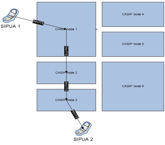
Figure 10 and Figure 11 show how SIP requests get routed within a CASIP network
Figure 11 Routing call setup requests in CASIP
The request is first routed to a CASIP node which then routes the request through the
CAN network to the final destination. The additional overhead due to CASIP comes
from CASIP routing, and additional SIP processing at the first CASIP node.
4.4
Locating a CASIP Node
When a SIP UA wishes to connect to the SIP network it either uses pre-configured SIP
URI of a SIP Server in that domain [12] or sends the SIP REGISTER request to either, a special SIP multicast address sip.mcast.net or 224.0.1.75 as specified by the SIP RFC
3261, and takes the first responder to the request to be its SIP Server. Alternatively a
queries for that domain. DNS SRV queries for a SIP domain yields the list of addresses
and port numbers of the SIP Servers associated with that domain [13]. In CASIP, a SIP
UA finds a CASIP node in the same way. By the CASIP routing strategy, any node can
route the request correctly to the final destination. When a UA discovers a CASIP node,
it uses that node for all the future requests. Using the same node to send SIP Requests
into the network allows us to use caching to optimize the number of hops the SIP
message traverses within the network (more discussion on this later in this section).
4.5
Join and leave
CASIP nodes also need a method to be able to join and leave the CASIP network
gracefully. When a node joins the network, it chooses a random point in the hash space
and sends a join request to any of the available CASIP nodes. That request is routed to
the zone in which that random point belongs to. The CASIP node that owns that zone,
then, splits the zone into two halves and transfers one half and the location information
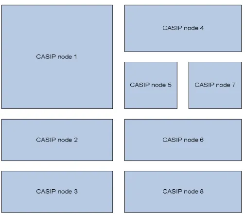
stored in that half to the node that is joining(Figure 12 and 13 depict a new node joining
the CASIP network, and how the hash space gets partitioned after the join, respectively).
It also informs the joining node of its neighbors and the routing information so that the
new node can effectively become a part of the CASIP network. While leaving the CASIP
network, a node sends a leave request containing the information about its associated
zone to its neighbors. This zone is then merged with one of its neighbors and the location
database entries previously stored by the leaving node are transferred to the node that
takes over that zone.
In the CASIP network, as zones are split or merged to accommodate new nodes or
leaving nodes, the information about new nodes occupying a zone must send information
about the new zone to its neighbors. These messages are called Zone Information
node. In order to maintain consistency, zone information messages are also exchanged
periodically.
Figure 12 New CASIP node sends JOIN request
In order to implement join and leave operations (which are not part of SIP), this
document proposes to introduce two new methods to SIP called JOIN and LEAVE, with fields to indicate the randomly chosen point in the hash space and the zone information
to the neighbors of a CAN node. Using SIP messages for the purpose of join and leave
gives us the advantage of using the same SIP stack that is used for routing call setup
messages. This thesis proposes to implement the zone information message as
lightweight UDP messages rather than as SIP messages, since they are much more
frequent than the JOIN and LEAVE messages. But for the join and leave procedures it might be advantageous to make use of the messaged based, but reliable transaction based SIP
stack. SIP also allows extensions to the protocol by adding new methods. The following
is the description of the SIP methods that are added by this thesis. Please note that the
formal syntax definitions described in this document are expressed in the ABNF format
used in SIP [1], and contain references to elements defined therein
This table expands on tables 2 and 3 in SIP [1].
Priority R - - Proxy-Authenticate 407 m m Proxy-Authorization R o o Proxy-Require R o o RAck R - - Record-Route R o o Record-Route 2xx,401,484 o o Reply-To - - Require - - Retry-After 404,413,480,486 o o Retry-After 500,503 o o Retry-After 600,603 o o Route R c c RSeq 1xx - - Server r - - Subject R - - Supported R o o Supported 2xx o o Timestamp o o To c(1) m m Unsupported 420 o o User-Agent o o Via c m m Warning R - o Warning r o o WWW-Authenticate 401 m m
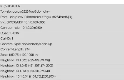
In a typical JOIN request (such as the one shown in Figure 14), the reqURI and the To headers are filled with a URI with the co-ordinates of the location it wishes to join in the
hash space. This is generally chosen at random so that the JOIN will split a zone at random, causing a uniform distribution of the hash space over the nodes. In case of a
load triggered addition of a node, then the JOIN has a reqURI generated to match the zone of the node whose load needs distribution. Figure 15 shows a response to a JOIN
JOIN sip: agsgw23234ag@domain SIP/2.0 To: sip: <agsgw23234ag@domain>
From: <sip:proxy10@domain> ; tag = zh234fasdfkjjlkj Via: SIP/2.0/UDP 10.1.0.100:6060
Contact: <sip:10.1.0.100:6060> CSeq: 1 JOIN
Call-ID: 1
Content-Length: 0
Figure 14 SIP JOIN Request
SIP/2.0 200 Ok
To: <sip: agsgw23234ag@domain>
From: <sip:proxy10@domain>; tag = zh234fasdfkjjlkj Via: SIP/2.0/UDP 10.1.0.100:6060
Contact: <sip: 10.1.0.30:6060> CSeq: 1 JOIN
Call-ID: 1
Content-Type: application/x-can-sip Content-Length: 234
Zone: {{50,75},{100,100}} : y
Neighbor: 10.1.0.23 {{25,49},{49,49}} Neighbor: 10.1.0.43 {{51,101},{74,200}} Neighbor: 10.1.0.30 {{50,50},{59,74}} Neighbor: 10.1.0.34 {{101,75},{200,200}}
4.6
Bootstrapping
The CASIP network starts with just one node owning all of the hash space, followed by
the other nodes joining the CASIP network. In order for a new node to join the network it
needs to know at least one CASIP node in the network. This can be achieved using the
same SIP mechanism to discover a SIP proxy. When a new node tries to join, it gets a list
of existing CASIP nodes either through SIP multicast address or using a DNS server that
holds a list of a few node that are already in the CASIP network.
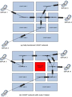
4.7
Failover handling
The CASIP node can effectively route messages even if some nodes in its neighbors
have failed (as shown in Figure 16). Failure can be detected using the ICMP destination
unreachable messages or a lack of periodic zone information messages for a timeout
period (In CAN, this timeout period is set proportionally to the size of zones 5]).
Using the same mechanism described for node leaving, neighbor can also take over the
zone of the failed node. However all the location information stored in the zone
corresponding to a failed node are lost. As SIP UAs periodically and frequently refreshes
their location information through means of periodic REGISTER requests, the CASIP network relies on these registrations to the location information lost during the failure. So
in a small registration refresh interval (typically, 5 minutes), the service can be
completely recovered. If the nodes are built using very highly available hardware, a
downtime of 5 minutes in a year caused by a single failure would still place the
availability of the networks at 5 nines (99.999%) which is an industry standard.
In case where the underlying hardware is not highly available, the CASIP network can
handle multiple, simultaneous failures and maintain the service highly available. One
maintaining more than one hash function. In this approach, the same content is replicated
to multiple nodes using different hash spaces. Since the location database is redundantly
replicated, single node failures will not lead to complete loss of location information
stored by the network for that zone. However this approach is different from the pure
replication discussed in Section 3 in sense that the whole hash space is not replicated on
every other node, there by allowing it to still be a scalable solution. This is in contrast
with the static partitioning approach, which might otherwise be considered as good an
approach as the CASIP approach. The ability of CASIP to take over a failed node with a
temporary additional load on one of its neighbors certainly is useful in deployments that
Figure 16 CASIP behavior during node failures
4.8
Optimization
The major disadvantages of the CASIP approach are the followings. (1) SIP messages
are traverse several overlay hops before reaching the final destination. A d-dimensional
CAN network can give about d/4(n1/d) hops. Thus, the hop count increases with the
be a physical neighbor. Thus, the network incurs high delay overhead. Each hop in the
SIP network introduces additional call setup delays. This delay becomes unacceptable
under a large number of nodes in the networks.
The acceptable call setup delays are in the range of 3 seconds to 8 seconds for Internet
telephony [6]. Push-to-talk applications require about 1.5 second call setup delays [3].
Our goal is to limit the call setup delays within these bounds. Since CAN increases hop
counts as the number of nodes grows, this cannot be achieved. One approach to solving
this problem is to use caching techniques to optimize the path length. The first CASIP
node encountered by a SIP Request is modified to look up its cache first to resolve the
location of a destination SIPUA. A cache miss results in the CASIP node routing the SIP
Request using normal CAN routing as suggested in Section 3.2. Several caching
techniques that can be applied to CASIP are as follows.
a.
: This technique is based on the data caching in CAN
as suggested in [5]. It caches the result of a query at the first CASIP node that a SIP
request encounters. This can be implemented by storing the resolved location of the
destination of a SIP request in one of the SIP headers in the SIP response sent back from
the destination SIP UA. The first CASIP node caches the resolved location information
for future requests to the same destination. Any future request arriving to that first node
can be resolved without routing. Although this technique reduces the path length of the
cached location information to one, it requires a huge number of cache entries at every
CASIP node since the subscriber base of a telecom carrier is in the order of millions.
Also the cached information will have consistency problems since the location may
change over time.
b. "!# %$&')(
* ),+
This technique is an enhancement to the previous technique.
In order to solve the consistency problem faced by the previous technique, this technique
location information of the destination SIP UA. This can be implemented using the same
approach as above using a special “Via” header parameter in the SIP response. The node
containing the location Information of a destination records its own IP address in a
header parameter. The first CASIP node encountered by the SIP request caches this
address, and forwards future SIP requests for that destination UA to the IP address in the
cache. This technique solves consistency because the serving node always contain the
location information of the destination UA and also even if the cached CASIP node fails
or is taken over by a different zone’s CASIP node, the SIP request can always be
rerouted to the correct destination using normal CAN routing. The cache entry at the first
node can be corrected when the response to that SIP request arrives at the serving node.
But this technique also leads to the same problem as of the previous approach: the size of
the cache is not manageable because one entry has to be created for each UA URI that
the first node serves.
c.
: This technique caches the coordinates of a zone and the IP address of
the CASIP node serving that zone. The d-dimensional coordinates of the zone containing
the destination SIP URI is recorded by the serving node in a special ‘Via’ header
parameter inserted by the serving node. The first node caches this zone coordinate and
the address (note that the entry is not created per URI). When a request arrives, the first
node initially hashes the request URI and then looks up an entry in its cache for the zone
containing the hash value of the URI. If the entry is found, it sends the request directly to
the IP address corresponding to that matching entry. Even if the zone information is
invalid due to addition or deletion of nodes, the correct information can be refreshed after
one cache miss. In this approach, the number of entries in the cache is kept to at most the
number of zones (or the number of nodes) in the network and also rerouting in the
d.
&&
: When a SIPUA registers with the CASIP network, it contacts an
arbitrarily chosen SIP proxy from the available proxies. The REGISTER request then gets routed from that first proxy node to the proxy containing the hash pace containing
the UA’s SIP URI. That serving node can be made to send a response directly to the SIP
UA, enabling the SIPUA to send subsequent periodic REGISTER requests to that node directly. REGISTER transactions contribute to about 75% of the SIP traffic in a SIP network. This optimization effectively cuts down one hop of additional SIP processing
required in the network, there by reducing SIP processing load on the servers
significantly. Also this helps in achieving high compression ratio, if SIP compression is
used in the network, by use of stateful compression since the SIPUA will always send
5. Performance results
5.1
Experimental Setup
In this section, the performance of the CASIP architecture is evaluated by analyzing the
design using simulation. A CASIP network using a network simulation (NS-2) on a
topology generated from a topology generator tool called GT-ITM [18]. The topology as
shown in Figure 17 consists of 100 internet backbone router nodes with inter-transit
delays set randomly between 40ms and 80ms using the tool. The transit-to-stub delays
were set to 10ms.The topology was divided into five geographical regions and 10 CASIP
nodes were attached to each region through stub nodes (each region is shown using the
big circles in Figure 17). SIP traffic generators were attached to each region and these
traffic generators created an aggregate load equivalent to the one generated by one
million subscribers (based on the peak load described in the introduction). These traffic
generators created both call setup requests and REGISTER requests. Using this simulation setup it was possible to study the SIP processing loads on each node, and the
average number of hops traversed by a SIP message, and the database update load on
each node. Also it was studied that the latency in call setup as the number of nodes in the
CASIP network increases, and also the number of messages exchanged as nodes join and
leave. The results were also compared to the performance of the shared database
5.2
Effect of CASIP on CPU load at each node
Three major loads on the CPU of each nodes were studied, 1. The load caused by SIP
messages processing 2. The load caused by database operations performed at the
co-located database at the node (in case of replicated database approach and CASIP) and 3.
The load caused by generating remote database operation requests and processing replies
to the requests (as in shared database and replicated database).
The SIP load generators were used to generate a load equivalent to that generated by 1
Million SIPUAs. This load was applied to the replicated database, shared database,
CASIP and optimized CASIP networks. The replicated database and shared database
approaches divided the SIP load equally among themselves there by reducing the load
per node as more and more nodes were added. CASIP and optimized CASIP also showed
a decrease in load as the number of nodes in the network increased. Although CASIP
experienced additional load due to the routing of SIP messages within the CASIP
network. In the case of optimized CASIP this routing overhead was greatly reduced since
any node was reachable from the first node receiving a SIP request in a single hop. Also
the periodic re-registrations were sent to the same node, there by cutting almost 75% of
the routing of SIP message within CASIP. So the optimized CASIP network followed
the replicated database and shared database in terms of SIP load. Figure 8 shows the
observed loads on the different approaches, the loads were calculated assuming that a
single node’s CPU can handle up to 500 transactions per second or 1000 SIP messages
per second. In the real world a single node will be able to handle only a maximum load
of 100% CPU utilization, the simulation is used only to show the effective load on each
0 200 400 600 800 1000 1200 1400 1600
1 4 7 10 13 16 19 22 25 28 31 34 37 40 43 46 49
Number of Node s
C P U L o a d i n P e rc e n ta g e replicated database shared database CASIP optimized CASIP
Figure 18 Load caused by SIP processing on each node
The call setup traffic cause database lookups on the co-located database in the proxy
nodes in case of the replicated database and the CASIP approach. And the Registrations
cause an update load on these co-located databases. Assuming 5000 Updates or 10,000
lookups can be performed from on a memory resident database. The load that these
database operations caused on the CPU at each node can be plotted as in Figure 19. It can
be noted that there are no local database operations in the case of shared database
approach. As the number of nodes are increased CASIP shows an increase in CPU load
caused by database operations, but replicated database exhibits a constant load due to the
0 10 20 30 40 50 60 70 80 90 100
1 4 7 10 13 16 19 22 25 28 31 34 37 40 43 46 49
Numbe r of Nodes
C P U L o a d i n P e rc e n ta g e replicated database shared database CASIP
Figure 19 Load caused by local database operations
Also studied was the load caused by the requests for remote database operations made
from a node. In the case of shared database, on receipt of a SIP request the node performs
a query or an update request (depending on whether the SIP Request was a REGISTER
or other requests). This involves formulating the query, formatting the query,
transmitting it over the network and processing the response to the query from the
database. In case of replicated database, each node propagates updates to its local
database operations performed in the case of CASIP. The load caused by these database
operations can be plotted as a graph as shown in Figure 20. It was assumed that a single
node’s CPU can process 5000 such database request and process the response from the
remote database. 0 20 40 60 80 100 120
1 4 7 10 13 16 19 22 25 28 31 34 37 40 43 46 49
Numbe r of Nodes
C P U L o a d i n P e rc e n ta g e replicated database shared database CASIP
Figure 20 Load caused by database operations performed over the network
The total load on the CPU on each node can be obtained by summing up the loads caused
by the above three operations (SIP processing, local database operations, remote database
operations), since all these operations must happen at the same time on each node (Figure
21). It is interesting to observer that optimized CASIP performs very close to the shared
database approach but totally eliminates the need for a centralized database. The
more nodes are added to the network. The number of nodes required for handling
1Million subscribers can be obtained by determining at how many nodes, the CPU load
becomes 100% or less from the graphs for each approach. For one million subscribers
shared database requires only 11 nodes and a shared database. But with 13 such nodes
the optimized CASIP approach was able to handle the same subscriber base without the
need for a centralized database. In the case of the replicated database approach the load
never falls below 100% even in spite of adding additional nodes, making it in feasible for
the replicated database approach to handle even a subscriber base size of 1 million.
0 200 400 600 800 1000 1200 1400 1600
1 5 9 13 17 21 25 29 33 37 41 45 49
Num be r of Node s
C P U L o a d i n P e rc e n ta g e replic ated s hared
c as ip
optimiz ed c asip
Figure 21 Total load on the CPU at each node
The above load graph can also be translated into Figure 22 to represent the number of
0 500000 1000000 1500000 2000000 2500000 3000000 3500000 4000000 4500000 5000000
1 4 7 10 13 16 19 22 25 28 31 34 37 40 43 46 49
Numbe r of Node s
N u m b e r o f S u b s c ri b e rs replicated database shared database
CASIP ( optimized )
Figure 22 Subscriber growth vs. number of nodes
5.3
Path length and call setup delays in CASIP
The path length of a SIP message within the SIP network is the number of CASIP nodes
it visits) in the network after the first node. The average path length in the shared
database approach and the replicated Database approach equals zero since the location
information of any SIP UA is available to them at that very first node. In CASIP, SIP
messages are always forwarded to neighbors with the smallest Cartesian distance to the
destination SIP URI’s hash. Hence the path length of a SIP message is the Cartesian
information of the destination SIP URI. The average path length in a d-dimensional CAN
with n nodes is of the O (n1/d) [5]. However, when zone caching is applied, the path
length converges to 1. Figure 23 shows the results of the simulation.
0 0.5 1 1.5 2 2.5 3 3.5 4
1 4 7 10 13 16 19 22 25 28 31 34 37 40 43 46
Num be r of Node s
A v e ra g e P a th L e n g th
CA SIP Optimized CA SIP (zone caching)
Figure 23 Average Path Length
Using the link delays in network simulator the call setup delays (Figure 24) in the
topology was measured. As predicted, the increasing setup delays of CASIP were due to
the increased path length. However, use of zone caching keeps the delay always below
250 ms. The call setup delays of the shared database approach is very close to the
optimized CASIP because the approach requires one hop to access database. The local
0 0.1 0.2 0.3 0.4 0.5 0.6 0.7
1 3 5 7 9 11 13 15 17 19 21 23 25 27 29 31 33 35 37 39 41 43 45 47
Num be r of SIP Pr oxy Node s
C a ll s e tu p d e la y i n s e c o n d s
replicated database CA SIP c entralized databas e optimized CA SIP
Figure 24 Call Setup delays in CASIP
0 50 100 150 200 250 300
1 3 5 7 9 11 13 15 17 19 21 23 25 27 29 31 33 35 37 39 41 43 45 47 49
Num be r of Node s alr e ady pr e s e nt
N u m b e r o f M e s s a g e s E x c h a n g e d
One Node A ddition 10 Node Addition 20 Node A ddition
5.4
Reconfiguration overheads
The number of messages exchanged between CASIP nodes whenever a new node joins
or a node leaves the CASIP network was measured. Figure 25 has the result. Since
addition or deletion only affected the routing tables of the immediate nodes of that
particular node, the observed number of exchanges of zone information between the
neighbors is very small. The message overhead is also independent of the total size of the
network. This is particularly important when considering the fact that the static
partitioning approach although similar to optimized CASIP in terms of routing, will
require the reconfiguration to be propagated to all the ‘n’ nodes in the network
immediately. The optimized CASIP requires that the reconfiguration be propagated only
locally before the system can functional again. The zone caching optimization will then
help establish the routing overhead to its minimum in a very few SIP requests that
follow. 0 20 40 60 80 100 120
0 5 10 15 20 25
Num be r of fa ile d node s
C a ll c o m p le ti o n p e rc e n ta g e
5.5
Effects of a failed Node
To measure the impact of failure, varying number of CASIP nodes in the network were
failed artificially and the effect of the failures on the call completion ratio were observed.
In a test where 50 nodes are used and one node was disabled, the call completion ratio
dropped by less than 2% before the node was re-enabled again. Once hash space of that
node is taken over, the SIP registrations quickly re-establish the location of the SIP URIs
in that zone, taking the call completion ratio back to 100%. It was also noted that even
during the failure of a node, calls that originally flowed through that node were
successfully routed around the failed node. The network was also observed when the
number of failed nodes was increased to 10% of the total number of nodes and also to
20% of the number of nodes of the network. At those high failure rates the call
completion ratios drop quite rapidly to 88% and 67% respectively. However, these
numbers are reasonable considering the magnitude of failures. In a commercial
deployment a single node failure by itself is considered critical; hence 20% of the nodes
failing are never bound to happen. However designing a network that can gracefully
degrade and provide at least partial availability during such failures, (unexpected
calamities or emergencies) might prove to be an advantage. Figure 26 shows the result.
Although this call completion ratio during the time of failure can be observed in a static
partitioning approach, there is no take over of the zone of the failed node by its neighbors
in the case of the static partitioning approach. This automatic take over of CASIP is a