Installation Manual
0450-0074 Rev. E
About ESI
ESI (Estech Systems, Inc.) is a privately held corporation based in Plano, Texas. Founded in 1987, ESI designs and builds innovative telecommunications products for businesses like yours. Because of their powerful com-bination of value and features, ESI products are consistently recognized by industry publications and leaders. In fact, ESI also creates telecommunications products for major companies to market under their well-known brand names.
Copyright © 1999–2002 ESI (Estech Systems, Inc.). Visit ESI on the Web at http://www.esi-estech.com.
IVX is a registered trademark of Estech Systems, Inc. Motorola and ColdFire are registered trademarks of Motorola, Inc. Act! is a registered
trademark of Symantec Corporation. Goldmine is a trademark of Goldmine Software Corporation. Microsoft, Windows and Outlook are
General description... A.1
Hardware overview/installation... B.1 Testing TAPI...B.20 Proceeding to use TAPI...B.20
System programming: an introduction... C.1
Function 1: System parameters ... D.1 Function 11: Initialize...D.1 Functions 12 and 13: Installer and Administrator passwords...D.1 Function 14: Set time/date...D.2 Function 15: System timing parameters...D.2 Function 16: Recording alert...D.3 Function 17: System speed-dial ...D.4 Function 18: Serial maintenance port baud rate ...D.5
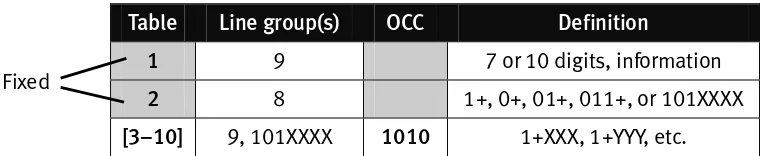
Function 2: CO lines...E.1 Function 21: CO line programming ... E.1 Function 22: Access codes/toll restriction... E.7 Function 23: CO line parameters... E.10 Function 24: Caller ID... E.12
Function 3: Extension programming... F.1 Function 31: Extension definition and routing...F.1 Function 32: Extension feature authorization...F.5 Function 33: Department programming ...F.7 Function 35: Extension button mapping...F.9
Function 4: Auto attendant programming ... G.1 Function 41: Auto attendant branch programming ...G.1 Function 42: Announce extension number...G.4 Function 43: Automatic day/night mode table...G.4
Function 5: Voice mail programming ... H.1 Function 51: Maximum message length ...H.1 Function 52: Message purge control...H.1 Function 53: Guest/info mailboxes ...H.2 Function 54: Group mailboxes and the broadcast mailbox...H.3 Function 55: Message notification...H.4 Function 56: Cascade paging mailboxes...H.5 Function 57: Q & A mailboxes...H.6
Function 6: Recording ... I.1 Function 61: Re-record system and auto attendant branch prompts... I.1 Function 62: Record directory names ... I.2 Function 63: Message-on-hold (MOH) programming... I.3
Function 7: Reports ... J.1
Index
Appendix I: IVX 128 user’s guide
General description
IVX 128 (IVX stands for Integrated Voice Exchange, while the 128 indicates the system’s maximum
number of call-processing ports) is an advanced business telecommunications system that includes not only phone service but also voice mail, an automated attendant, automatic call distributor (ACD) and computer integration.
The system itself is housed in a surprisingly small case that is wall-mounted in the telephone equipment room. An external, wall-mounted power transformer powers the system.
Programming of the system can be done locally or remotely through either the phone or the
Windows®
-based Esi-Access program (on a PC-compatible computer which has either dialed into
the system from another location or is physically connected to its RS-232C serial port).
Telephone system features
IVX 128 expands from its basic six-line, twelve-station configuration to handle as many as 66 CO lines (see “System capacity,” page B.3).
For offices with higher-bandwidth needs, T1 support is also available through the installation of one or two DLC12 cards.
• Impressive expansion capability — Handles up to 66 CO lines and up to 84 stations. • T1 support — Can connect to higher-bandwidth lines, which more and more offices use. • Digital Feature Phone — Compact, rugged design; includes a high-quality speakerphone, large
and informative multi-functional display, and a specially designed key layout with several dedi-cated keys to minimize or eliminate the need to memorize codes. (A TAPI model is available; it’s compliant with Basic Telephony Service.)
• Extensive help — Verbal User Guide™
uses spoken and displayed help prompts to help everyone from the installer through the administrator down to the least experienced end user. Easily ac-cessible with one press of PROG/HELP.
• Enhanced Caller ID — Allows one-touch automatic message return.1
• Live call recording — Can record any conversation or personal memo, with moving or copying of any recording to another user’s voice mailbox (see “Voice mail features,” below).
• Call waiting — Includes helpful display, showing both calls’ Caller ID information, and easy one-key toggling between calls.
• Conference calling — Includes 24 conference bridges, and a conference may contain up to four parties, so IVX 128 can support six conferences of four parties each or eight conferences of three parties each.2
• Esi-Dex™
speed-dialing — Calls any number from three separate lists (personal, station and system); uses Caller ID1
information or direct keypad entries.
• Dedicated overhead paging interface — Allows for external paging through overhead speakers or multi-zone paging units (amplification required).
1
This and all other references to Caller ID service within this manual assume the end-user organization subscribes to Caller ID service from its telephone service provider.
2
• 911 alert — Provides immediate line access if any station with line access dials 9 1 1 to report an emergency; sends a message via the serial port indicating the start date, time, station num-ber and end-time of the 911; also sounds a warning tone at the operator station and displays, for example:
911 CALL FROM
X102 JOHN JAMES
Voice mail features
• 16 built-in voice mail ports — These are in addition to the up-to-128 possible call-processing ports; thus, you may build the system to its maximum for call-handling without having to bal-ance voice mail needs versus call-handling needs.
• Highest-grade voice quality (64-kilobit/second sampling) for voice mail and other storage of voice messages.
• Eight message-on-hold recordings — Among these are three prerecorded tracks; also supports live entry.
• Off-premises message delivery.
• Urgent messages — Can deliver higher-priority messages first.
• Several different mailbox types, including group, broadcast, informational, cascade paging and Q & A.
• Message Recycle Bin (undelete) — Remembers, and can restore, each mailbox’s 10 most re-cently deleted messages
• Quick Groups™
— Makes it easy to leave voice mail messages for several users. • Quick Move™
— Records a conversation into another user’s mailbox. • Virtual Mailbox Key™
allows easy monitoring of a second mailbox.
Auto attendant features
• Six levels, 100 branches — Allow you and your customer to set up a more caller-friendly answer-ing environment, includanswer-ing a company directory.
• Virtually unlimited call routing — Includes off-premises transfer, pager notification, more.
ACD features
• Routes calls within designated departments for quickest possible call answering.
Hardware overview/installation
IVX cabinet components consist of:
• Base Cabinet I
• Main board
• Memory Module
• One port card
(configured with 612, 684, A12, D12 or DLC12 card)
• External wall-
mounted transformer
• Base Cabinet II
• Expansion board
• External wall-
mounted transformer
• Up to two port cards
• Configured with a D12, A12, 612, 684 or DLC12 card
• Expansion Cabinets (optional)
• Up to two port cards
• Configured with a D12, A12, 612, 684 or DLC12 card
Base Cabinet I
The wall-mounted Base Cabinet I measures 81/
2″ W × 11″ H × 3″ D, and is designed for easy
instal-lation and easy component access. It houses the Memory Module and Main Board, a 612, 684, A12, D12 or DLC12 port card (see page B.2), two serial ports and a MOH connector. It can support one Expansion Cabinet, for a total of three port cards.
Base Cabinet II
To expand the system beyond the Base Cabinet I (and its Expansion Cabinet), connect a Base Cabi-net II via ribbon cable to the Base CabiCabi-net I. The Base CabiCabi-net II houses up to two port cards; it can also support one Expansion Cabinet.
Expansion Cabinets
You can “piggy-back” an Expansion Cabinet to the front of each Base Cabinet. Each Expansion Cabinet houses up to two additional port cards each, enabling the system to grow to its maximum 128-port configuration (seven port cards).
Main board
The main board combines leading-edge hardware components — including a Motorola® ColdFire®
processor and DSP structure — along with proprietary operating system software. The board provides:
• System control of the Memory Module and port cards • Two standard RS-232C DB9 serial ports
• A built-in 33.6 Kbs modem for remote access • An external paging-device interface
Wall-mount transformers
With three or fewer port cards, Base Cabinet I requires a 3-amp transformer (supplied). With four to seven Port Cards, Base Cabinet I requires a 5-amp transformer and Base Cabinet II a 3-amp transformer. Base Cabinet I is shipped with and uses a 3-amp wall mount transformer to support up to three port cards (Base cabinet I and an Expansion Cabinet). However, when Base Cabinet II is added, Base Cabinet I will require the wall-mount transformer to be swapped with the 5-amp transformer that is supplied with the Base Cabinet II.
Memory Module
The Memory Module — a hard disk drive with proprietary formatting — contains all system pro-gramming and configuration data, and pre-loaded voice prompts. The Memory Module provides 140 hours of voice storage at 64 kilobits/second — the industry's highest-quality sampling rate.
Port card options
Five kinds of port cards are available for IVX 128. All port cards can be mounted in any slot in either of the Base Cabinets or the Expansion Cabinet. Each port card is equipped with a standard female amphenol connector for easy wiring to a standard 66 or 110 block.
• 684 — Provides circuits to connect up to six analog loop-start CO lines, eight Digital Feature Phones and four analog station ports. The CO line ports support standard CO and Centrex loop-start lines; ground-start CO lines are not supported. The analog ports provide a standard 24-volt, two-wire connection to fax machines, courtesy phones, modems, etc. Only one analog device can be
con-nected to each analog station port. This card uses 12 station ports and six CO ports when installed. • 612 — Provides circuits to connect up to six analog loop-start CO lines and 12 Digital Feature
Phones. Ground-start CO lines are not supported. This card uses 12 station ports and six CO ports when installed.
• A12 — Connects up to 12 analog devices, such as fax machines and cordless phones. This card uses 12 station ports and no CO ports when installed. Each port provides a standard 24-volt, two-wire phone connection. Only one analog device can be connected to each port.
• D12 — Connects up to 12 Digital Feature Phones (only). This card uses 12 station ports and no CO ports when installed.
• DLC12 — (Digital Line Card) Includes interface circuitry to connect a single T1 span. Any of (or all)
24 channels of the T1 span can be assigned, and the DLC12 supports loop-start, ground-start, E&M and DNIS/DID trunk types with immediate, wink-start or dial-tone-start signaling. The DLC12 is equipped with a built-in CSU that can be connected directly to a network interface unit or SmartJack. When installed in an IVX 128 Plus system, it can be connected also to an ISDN PRI; for more information, refer to IVX 128 Plus: Additional Features (ESI part #0450-0201).
Digital Feature Phones
The IVX Digital Feature Phone is equipped with speakerphone, 32-character LCD display, and both fixed and programmable feature keys. Phones connect to the cabinet via standard two-wire twisted pair.
TAPI Phone
The TAPI Phone is an optional version of the Digital Feature Phone. It provides a DB9 connector and RS-232C cable to facilitate connection to a PC serial port for Basic Telephony Integration to such standard packages as Act!®
, Goldmine®
and Outlook®
. A Digital Feature Phone cannot be field-upgraded to a TAPI Phone.
64-Key Expansion Console
The 64-Key Expansion Console adds 64 additional programmable feature keys to a designated user's extension. The console is connected to its host phone via a special “Y” cable (provided) and does not require a separate station port of its own.
Note: Up to 20 64-Key Expansion Consoles can be installed in a fully configured system: • Six on Base Cabinet I
• The additional 14 on Base Cabinet II
System capacity
• Five fixed ports
• 2 serial
• MOH
• Modem port
• Overhead paging
• 126 call processing ports (128, minus paging and modem ports)
• 84 combined digital and analog stations3
, maximum
• 42 CO lines, maximum (66 if DLC12 cards are used)
Note: If DLC12 cards are used and the maximum CO lines exceed 42, then a maximum of 84 sta-tions cannot be achieved. The total ports cannot exceed 126. If a DLC12 card is installed, the system sets 24 ports for COs, even if a fractional T1 is used.
3
Example: Seven port cards are installed, including one T1-configured DLC12 card and standard loop lines as shown below. Only 72 stations can be installed; i.e.:
126 minus (6 + 6 + 6 + 24 + 0 + 6 + 6) = 126 minus (54) = 72 The last 12 stations on Card #7 cannot be used.
Port card Card type Lines installed Stations
1 684 6 12
2 684 6 12
3 612 6 12
4 DLC12 24 12
5 A12 0 12
6 612 6 12
7 612 6 0
Cautions
Important: This information complies with the requirements of Underwriters’ Laboratories (UL) and UL Standard 1950.
When using this telephone equipment, always exercise basic safety precautions in order to minimize the risk of fire, electric shock or injury to persons. Before proceeding, please read the following: • The airflow vents on the IVX case must be free of obstruction for proper cooling. Similarly, do not
install the cabinet in areas of extreme heat or improper ventilation. Never insert objects of any kind through the ventilation slots on the system cabinet; doing so may result in contact with dangerous voltages — or cause an electrical short capable of producing fire or shock. • Do not use liquids or aerosols to clean any IVX equipment; rather, use a cloth that is only
slightly damp.
• The IVX telephone/voice-mail system contains no components that are serviceable by
either non-dealers or non-manufacturer technicians. All service must be referred to the dealer for further handling.
• To reduce the risk of fire, use only 26 AWG or better telecom wire.
Power supply
Always disconnect the power supply and telephone lines from the system cabinet before opening the case for service or component disassembly or replacement.
Heed all warnings and instructions in documentation or marked on the cabinet or peripheral equipment.
Fuse
Contact the factory before attempting to replace the fuse. The fuse is located on the motherboard directly next to the power jack marked with “F1.”
Battery
“Caution: There is a danger of explosion if the onboard lithium battery is incorrectly
Regulatory information
United States of America
RegistrationThe CO line telephone numbers, FCC registration number, and ringer equivalence number (REN) of this equipment must be provided to the telephone company before installation. (See below for FCC registration number and ringer equivalence number.)
FCC Part 15
This equipment has been tested and found to comply with the limits for a Class A digital device, pursuant to Part 15 of the FCC Rules. These limits are designed to provide reasonable protection against harmful interference when the equipment is operated in a commercial environment. This equipment generates, uses and can radiate radio frequency energy and — if not installed and used in accordance with the instruction manual — may cause harmful interference to radio communica-tions (in which case, the user will be required to correct the interference at his/her own expense).
FCC Part 68
This equipment complies with Part 68 of the FCC Rules. On the bottom of this equipment is a label that contains, among other information, the FCC Registration Number and Ringer Equivalence Number (REN) for this equipment. You must, upon request, provide this information to your telephone company.
The REN is helpful to determine the quantity of devices you say connect to your telephone line and still have all of those devices ring when your telephone number is called. In most, but not all, areas, the sum of the RENs of all devices connected to one line should not exceed five (5.0). To be certain of the number of devices you may connect to your line, as determined by the REN, you should contact your local telephone company to determine the maximum REN for your calling area. If your telephone equipment causes harm to the telephone network, the telephone company may discontinue your service temporarily. If possible, the telephone company will notify you in advance but, if advance notice is not practical, you will be notified as soon as possible. You will be informed of your right to file a complaint with the FCC.
Your telephone company may make changes to its facilities, equipment, operations or procedures that could affect the proper functioning of your equipment. If so, you will be notified in advance, to give you an opportunity to maintain uninterrupted telephone service.
If you experience trouble with this telephone equipment, the telephone company may ask that you disconnect this equipment from the network until the problem has been corrected or until you are sure that the equipment is not malfunctioning. This equipment may not be used on coin service provided by the telephone company. Connection to party lines is subject to state tariffs.
Installation: The device is equipped with a USOC connector.
Registration Number: 1T1USA-33727-MF-E
Regulatory information
Dominion of Canada
NoticeThe Industry Canada label identifies certified equipment. This certification means that the equipment meets telecommu-nications network protective, operational and safety requirements as prescribed in the appropriate Technical Equipment Technical Requirements document(s). The Department does not guarantee the equipment will operate to the user’s satis-faction.
Before installing this equipment, users should ensure that it is permissible to be connected to the facilities of the local telecommunications company. The equipment must also be installed using an acceptable method of connection. The customer should be aware that compliance with the above conditions may not prevent degradation of service in some situations.
Repairs to certified equipment should be coordinated by a representative designated by the supplier. Any repairs or alterations made by the user to this equipment, or equipment malfunctions, may give the telecommunications company cause to request the user to disconnect the equipment.
Users should ensure for their own protection that the electrical ground connections at the power utility, telephone lines and internal metallic water pipe system, if present, are connected together. This precaution may be particularly important in rural areas. Caution: Users should not attempt to make such connections themselves, but should contact the appropri-ate electrical inspection authority, or electrician, as appropriappropri-ate.
Ringer equivalence number (REN): 0.4
Notice
The ringer equivalence number (REN) assigned to each terminal device provides an indication of the maximum number of terminals allowed to be connected to a telephone interface. The termination on an interface may consist of any combina-tion of devices subject only to the requirement that the sum of the RENs of all the devices does not exceed 5.
Hardware installation
Site location
As with most electronic equipment, the environmental considerations for this site need to observe good common sense. Provide a dry, clean, and accessible area.
Locate space in the telephone equipment room, which will provide easy connection to the 66 blocks and 110VAC power. The location should be no further than 1,000 feet from the farthest station. Ambient room temperature must be 400
–800
(F.), and relative humidity no higher than 90%. Note: Do not place the equipment or station runs near high voltage electrical equipment or
Base Cabinet I
Base Cabinet II
Opening the cabinet
The lid on all cabinets is held in place by two tabs that rest in slots in the bottom of the case, and a release tab that snaps into an opening in the top-center of the cabinet and is secured by a retaining screw.
To remove the lid:
1. Remove the retaining screw and depress the release tab at the top of the cabinet.
2. Rock the lid back from the top.
3. Lift and pull the lid free from the slots in the bottom of the cabinet.
Mounting the Base Cabinet(s)
Use three #8 hex-head screws. Note the position of the three mounting holes in IVX. Allow room for installation of the second base cabinet either now or if required in the future. The Base Cabinet II must be installed directly below the Base Cabinet I. Allow about 2″ clearance between the units.
1. Screw in the top screw to the backboard (at least half-inch thick plywood) leaving about one-eighth-inch clearance between the screw head and the plywood.
2. Hang the unit using the keyhole at the top of the case.
3. Level the unit and install the bottom two screws.
4. If necessary, repeat the steps for the Base Cabinet II.
Expansion Cabinet installation
The Expansion Cabinets provide for the expansion of each base cabinet with two additional port cards. Each houses up to two port cards that are connected via ribbon cables through the opening in the back of the expansion cabinet to the base cabinet.
To install an Expansion Cabinet:
1. Wear a grounding strap and avoid unnecessary movement while handling the circuit boards.
2. Unplug the power to IVX.
3. Remove the Base Cabinet lid by pressing the release tab at the top of the Cabinet and rock back the lid from the bottom of the Cabinet.
4. Install the Expansion Cabinet on the front of the Base Cabinet in place of the Base Cabinet's lid.
5. Lock the Expansion Cabinet to the Base Cabinet by snapping the top in place and reinstalling the retaining screw.
6. Connect the grounding strap from the Expansion Cabinet's grounding lug (located on the bottom of the cabinet) to the Base Cabinet's grounding lug. Follow the grounding procedures as described earlier for grounding the Base Cabinet.
7. Through the large opening in the back of the Expansion Cabinet, connect the ribbon cable(s) from the port card(s) to the card directly below.
8. Re-install the original lid from the Base Cabinet on the face of the Expansion Cabinet.
Base Cabinet II installation
To expand the system beyond three Port Cards, Base Cabinet must be added. Mount Base Cabinet II directly below Base Cabinet I allow about two inches between them.
1. Connect the ribbon cable from the back of Base Cabinet II to the connector located on the bottom of Base Cabinet I.
2. Connect the ground of all units to the system ground.
Main Card
Port Card 2 Port Card 3
Expansion Cabinet Base Cabinet I
Port Card 1
Exp ansi on
Port Card 6 Port Card 7
Expansion Cabinet Base Cabinet II
Port Card 5
Port Card 4
Port card installation
Adding or replacing port cards will require the system to be taken out of service. Wear a grounding strap and avoid unnecessary movement while handling the circuit boards.
1. Unplug the power supply to IVX.
2. Two port cards may be installed in Base Cabinet II and in each expansion cabinet — one above the other. Each is ribbon-cabled to the port card (or main board) directly below it. (You’ll need to remove the uppermost card in each cabinet to gain access to the lower card.)
3. To remove a port card, disconnect the amphenol connector from the card. Carefully unplug the ribbon cable that runs to the port card or main board directly below it. Remove the 6 Phillips screws and remove the card from the cabinet.
4. To install a port card, observe the locations and relative positions of the card over the stand-offs. Install the 6 Phillips screws, connect the ribbon cable to the connector to the board directly below it and connect the amphenol cable.
Memory Module
Note: The Memory Module has a proprietary formatting scheme — do not attempt to install a non-ESI drive.
Adding or replacing the Memory Module will require that the system be taken out of service. Re-placing the Memory Module erases all its configuration data and customer recordings. (Prompts stay intact, however.)
LED functions
The unit's various LEDs are designed to provide visual feedback as follows:
Power LED
The Power LED is located on the top-right side of the cabinet and is illuminated when power is being applied to the system. This LED blinks periodically to indicate that the main processor is operational.
Port LEDs
The Port LEDs are located above their respective amphenol connectors on the right side of the cabinet. Each LED is illuminated when any port on its associated port card is in use.
Note: Disconnecting an amphenol connector when its respective LED is lit will cause any of its ports that are in use to be disconnected.
Upon power-up, approximately five minutes are required for the system to configure. The Power and Port LEDs will blink three times to indicate that the power-up sequence has been completed.
Note: When a DLC12’s LED is . . .
• . . . blinking, the T1 line is out of service.
• . . . not lit at all, the T1 line is in service but is idle.
• . . . lit solidly, the T1 line and/or a station on the card is in use.
Memory Transfer LED
External connections
Grounding instructions
IVX grounding (supplemental ground) is as follows:
• The conductor wires can be no smaller than the ungrounded branch-circuit supply conductors (usually 16-gauge or higher).
• Acceptable wire: bare or covered with green (or green-and-yellow-striped) jacket.
• Conductors (and power receptacles) shall connect to earth ground at the service equipment (usually a cold water pipe or copper ground rod).
• The supplemental ground must: be used regardless of power cord ground, be connected to the ground lug on the bottom of the IVX cabinet, and retain ground connection when IVX power sup-ply module is unplugged.
• Connect the grounding lugs of all units to system ground
Note: IVX lines are protected against a 10 KV surge only if the earth ground procedures described above are followed.
Power
Each base cabinet requires a 110 VAC outlet (if possible, a dedicated outlet). Use only the Class-2 power supply module provided. Expansion Cabinets, as well as the 64-Key Expansion Console, require no additional AC power. A clean, isolated power source in conjunction with a UPS is STRONGLY recommended. Each base cabinet draws a maximum of 25 watts. A fully loaded system draws no more than 50 watts.
If AC power is interrupted, the system will drop all connections. When power is restored, the system will resume normal operation in approximately five minutes, having retained its full programming and clock setting.
UPS
For system protection and to maintain uninterrupted operation, an Uninterruptible Power Supply is STRONGLY recommended. A UPS rated for 200 VA will provide approximately two hours of uninter-rupted service for a fully loaded IVX. Every 50 VA of capacity added to the UPS will yield
MOH port
The MOH (messages-, or music-, on-hold) connector on the upper right side of the cabinet is a standard 1
/8″ monophonic mini-jack, used for loading custom MOH recordings or for playing live
music-on-hold from an external source such as a radio or CD player.
Serial ports
Two standard DB9 serial connectors are located on the side of the cabinet. Use a standard shielded serial cable, DB9-to-DB9, for printer-to-computer (this is usually male-to-female).
Note: The maximum distance from the cabinet is 100 ft.
The output from each serial port is, 8 data bits, 1 stop bit, and no parity. The pinout is:
Data Transmit Pin 2
Receive Pin 3
Ground Pin 5
SMDR port
(Called “Port 1” in system display.)
Real-time SMDR call records are continuously output to the SMDR port.
Range: Programmable for 300, 1,200, 2,400, 4,800, 9,600, 19,200, or 38,400 bps. Default: 38.4K.
Maintenance port
(Called “Port 2” in system display.)
A laptop PC can be connected to this port for on-line programming and diagnostics. Reports gener-ated in Function 7 are also output to this port.
External paging device connection
A dry contact overhead-paging device can be connected to the system through the first port card's 66 block.
The overhead paging port is fixed (located on the main board) as extension 199 for programming purposes and user access.
Audio connection
The audio pair is connected to the 66 block at terminal 33 and 34. The pair’s impedence is 600 ohms.
Dry contact control
The manner in which the dry contact pair is punched down on the 66 block sets the pair as nor-mally open (sending a page to the port will close the contacts) or nornor-mally closed (sending a page to the port will open the contacts).
Connect the dry contact pair of the device to IVX as follows: • Terminals 35 and 36 to provide normally open operation
or
• Terminals 35 and 37 to provide normally closed operation. The port can be used with zone paging units.
Note: The port doesn’t support talk-back paging (which requires a CO port), nor does it support CO ring through the port.
Amphenol cable connections
Connect a standard 66 Block to each port card using a male 50-pin amphenol cable to each port card female connector located on the bottom-right side of the cabinet. The connector closest to the wall is the first card. CO line numbering will be greatly simplified if DLC12 cards are installed as the last cards.
CO line connection
Local loop
IVX's advanced CO line circuitry provides for open loop detection and IVX’s built-in Caller ID inter-face. Loop start lines are connected via the last 6 pairs on each 66 block on the 612 and 684 cards. Note: Observe correct order of connection to preserve proper rotary hunting of the CO lines.
T1
Up to 24 CO line interfaces (selectable as loop start lines or ground start trunks) are connected through two pairs punched down on the 66 block connector of the DLC12 card.
Up to two DLC12 cards can be installed. Note that the total line capacity of the system is 66.
Line numbering plan
If a DLC12 card is not used, the line number will begin with 1 on the first port card and end with 42 on the last port card.
Port card Line numbers
1 1 through 6
2 7 through 12
3 13 through 18
4 19 through 24
5 25 through 30
6 31 through 36
7 37 through 42
Allocate 24 CO line numbers for each DLC12 card and continue the numbering on the next card. The example below shows a DLC12 card as the fourth card.
Port card Card type Line numbers
1 684 1 through 6
2 684 7 through 12
3 612 13 through 18
4 DLC12 19 through 42
5 612 43 through 48
Special information: DLC12
The DLC12 card, one of the five available port cards for IVX 128, is a plug-in design that can be installed in any of the seven available card slots on the system highway. Each card provides a T1 interface supporting 24 DS0 channels and 12 digital stations.
IVX 128can have a maximum of two DLC12 cards per system and can provide up to 48 DS0 channels and 24 digital stations per system. Partial T1 applications are supported through line programming. Connection to the card is provided through an “industry-standard” 50-pin amphenol connector. The DLC12 card has built-in CSU functionality, eliminating the need for an external unit. The inte-grated CSU can be enabled or disabled via system programming (see “Function 2124: CSU
emulation,” page EE.6). The following functionality is provided: line, payload, DTE and none (normal operation) loopback modes with the ability to respond back controlled via system programming; alarm conditions, and both ANSI T1.403 and TR 54016 performance messages for ESF only. The DLC12 card supports these trunk types:
• Loop start • Ground start
• E&M — When an E&M trunk is selected, the choices for outgoing signaling type are immediate start, wink start and dial tone start; and the incoming signaling type choices are immediate start and wink start. The E&M trunk can be set for 2-way traffic, inbound traffic only or outbound traffic only.
Dial tone and ringback can be provided when required. These selections are set for each trunk.
The card supports the following framing format and line coding: • ESF/B8ZS
• SF(D4)/AMI • ESF/AMI • SF/B8ZS
Line compensation is provided as necessary between the CSU/DSU and IVX 128.These selections apply to all trunks on the DLC12 card. Many variables can affect the volume of the T1 lines. Different volume levels may be required when connecting a DLC12 card depending on the signal level of the T1. The volume level can be adjusted by increasing or decreasing the digital pad setting. These adjust-ments are made independently to each of the T1 lines. There will not be any support for pulse dialing; all incoming dialing will default to DTMF digits.
Station connection
The first 12 pairs on each amphenol are station ports (either 12 digital stations on the 612 or DLC12 card or eight digital stations and four analog ports on the 684 port card).
All stations are connected using a single pair. Each port position is pre-numbered and fixed as indicated in the 66 Block Wiring Diagram shown for each port card type.
Note: The station runs can be up to 1,000 ft.
Digital stations
The digital station wiring is not polarity-sensitive. Only one phone can be connected per digital port.
Analog ports
The analog ports do not require that tip-and-ring polarity be observed. The analog ports can be used for 2500 type sets or for devices such as fax machines, modems, etc., that can be connected via a normal tip-and-ring pair. Each analog port will support only a single analog device.
Station Numbering Plan
Each port card has 12 station interfaces. The station numbering plan starts with the first pair on the first port card as 100 and ends at 183 on the 7th port card.
Port card Station numbers
1 100 through 111
2 112 through 123
3 124 through 135
4 136 through 147
5 148 through 159
6 160 through 171
Installing the TAPI Phone
Important: To install the TAPI drivers to a PC with Windows NT 4.0 where Service Pack 3 (or greater)
hasn’t been installed, please obtain the latest Service Pack — currently, Service Pack 6a, or “SP6a” — from the following link and install it before continuing:
http://www.microsoft.com/ntserver/nts/downloads/recommend/SP6
Requirements
To perform this installation, you will need:
• An IVX Series TAPI Phone (Digital Feature Phone with TAPI interface).
• A PC running Windows 95, 98, ME, NT, 2000 or XP and with an unused COM (serial) port.
• A serial communications cable — A DB9 male-to-female cable is shipped with the TAPI Phone. If the PC has a 25-pin serial connector, you’ll need to obtain a DB9-male-to-DB25-female adapter (such as Radio Shack®
model # 26-287).
Also, if Caller ID integration is desired, you should confirm that (a) Caller ID is enabled on the IVX Series phone system and (b) the telephone company is providing Caller ID service.
Procedure
Note: If using the CD-ROM shipped with the TAPI Phone, proceed to step 1. Otherwise, skip to step 2.
1. Insert the CD-ROM into the PC’s CD-ROM drive; then browse to the CD-ROM drive and locate the
Esiivx.exe file. (Depending on your settings, the file may appear as just Esiivx.) Skip to step 5.
2. Use your Web browser to reach http://www.esi-estech.com/ivx_all/software.html#TAPI2000.
(You’ll need your ESI Resellers’ site password.)
3. To download the software, click on the link to the TAPI 2000 software listed as “For use with IVX Series TAPI Phones.”
4. When prompted, select a folder in which to save the software. (We suggest C:\Windows\Temp.)
5. The software is a self-extracting installer. To launch the installation process, browse to the
Esiivx.exe file and double-click on it.
6. If asked whether you wish to continue, click on Yes. Then, follow the instructions that appear.
7. At the end of the installation, you’ll be prompted whether you wish to restart the PC. Click on Finish.
8. As the PC restarts, a window will appear asking you to select the COM (serial) port that will be used for TAPI activity. Select the appropriate port and click on OK.
9. Connect one end of the provided serial cable to the PC serial port selected in step 8. Connect the other end to the serial port on the back of the TAPI Phone (see diagram, below).
You have now successfully installed the TAPI 2000 Windows telephony driver. Continue to the next
page to test the operation of the TAPI interface. Nine-pin
serial connection
IVX Series TAPI Phone
(rear view) COM
port RS-232C
serial cable
PC (rear view) Female plug
Testing TAPI
Windows includes a simple TAPI application called Phone Dialer that can be used to test the TAPI
interface by dialing a phone number. Two versions of Phone Dialer are currently available.
Depend-ing on which version of Windows you have, follow the appropriate test procedure for the Phone Dialer software on your PC.
Testing with Phone Dialer (Windows 95/98/ME)
1. Click on the Windows Start button; then click on Run, type Dialer in the Run window and click
on OK. This will start the file Dialer.exe.
2. In the Phone Dialer window, click on the Tools menu; then click on Connect Using...
3. In the Line field, select ESI IVX Telephony Service Provider and click on OK.
4. Once again, click on Tools; then click on Dialing Properties...
5. Enter the local area code and the appropriate access codes for an outside line; to insert a pause, use a comma (e.g., for local calls, you might use 9,).
6. Make sure the To disable call waiting, dial: box is not checked. Then, click on OK.
7. In the Phone Dialer window, enter the number to dial and click on Dial.
8. If the TAPI installation was successful, the phone’s SPEAKER key will light up and you’ll hear the phone number being dialed. If the call can’t be completed, add one or more commas to the outside access codes; also, verify that the other dialing properties are correct for the area from which you’re calling.
Testing with Phone Dialer 1.0 (Windows NT/2000/XP)
1. Click on the Windows Start button; then click on Run, then click on Run, type Dialer in the Run
window and click on OK. This will start the file Dialer.exe.
2. In the Phone Dialer window, click on the Edit menu; then click on Options.
3. In the Options window, click on Phone and Modems Option.
4. In the Phone and Modems window, a location entry should be highlighted. Click on Edit.
5. In the Edit Locations window, e nter the local area code and the appropriate access codes for an outside line; to insert a pause, use a comma (e.g., for local calls, you might use 9,).
6. Make sure the To disable call waiting, dial: box is not checked. Then, click on OK.
7. In the Phone and Modem Options window, click on OK.
8. In the Options window, under Line Used For..., select ESI IVX Telephony Service Provider and
click on OK.
9. In the Phone Dialer window, click on Dial and enter the number to dial in the Dial window. Then, click on the Phone Call radio button, followed by the Place Call button.
64 Key Expansion Console connection
Important: There are two different types of IVX Series telephones: Revision F (and later), and pre-Revision-F; each has separate procedures for installing a 64-Key Expansion Console. It’s easy to identify a Revision F (and later) telephone, because it has three jacks on the bottom — one for the 64-Key Expansion Console, one for the line cord and one for the handset.
Installing the Console on a
Revision F (or later) telephone
1. Connect one end of the expansion cable to the DSS connector on the IVX Digital Feature Phone.
2. Connect the other end of the expansion cable to the 64-Key Expansion Console.
3. To keep cables out of the way, thread the cable connecting the telephone and the 64-Key Expansion Console into the slots on the bottom of the phone and 64-Key Expansion Console.
4. Program the keys on the expansion module using the same procedure as with the Digital Feature Phone (press PROG/HELP 2).
5. For the customer’s convenience, label the paper overlay to show how the keys are programmed (you may prefer to use the Esi-Access PC software application for this).
6. Install the labeled ppaper overlay on the 64-Key Expansion Console.
7. Install the clear pplastic overlay oover the paper overlay to protect it. Use the provided Velcro®
tape to attach the left side of the 64-Key Expansion Console to the right side of the IVX Digital Feature Phone.
Installing the Console on a pre-Revision-F telephone
1. Connect the shortest part(one-inch) of the expansion cable to the IVX Digital Feature Phone.
2. Connect the 11-inch part of the expansion cable to the 64-Key Ex-pansion Console.
3. Plug the longest portion of the expansion cable into the tele-phone wall jack.
4. To keep cables out of the way, thread the two cables connecting the telephone and the expansion module into the slots on the
5. Program the keys on the expansion module using the same procedure as with the Digital Fea-ture Phone (press PROG/HELP 2).
6. For the customer’s convenience, label the paper overlay to show how the keys are programmed (you may prefer to use the Esi-Access PC software application for this).
7. Install the labeled ppaper overlay on the 64-Key Expansion Console.
8. Install the clear pplastic overlay oover the paper overlay to protect it.
9. Use the provided Velcro®
A12 port card
Term Wire color Signal RJ11 Port
1 White-Blue Tip Green
2 Blue-White Ring Red
Analog
3 White-Orange Tip Green 4 Orange-White Ring Red
Analog
5 White-Green Tip Green
6 Green-White Ring Red
Analog
7 White-Brown Tip Green 8 Brown-White Ring Red
Analog
9 White-Slate Tip Green
10 Slate-White Ring Red
Analog
11 Red-Blue Tip Green
12 Blue-Red Ring Red
Analog
13 Red-Orange Tip Green 14 Orange-Red Ring Red
Analog
15 Red-Green Tip Green
16 Green-Red Ring Red
Analog
17 Red-Brown Tip Green
18 Brown-Red Ring Red
Analog
19 Red-Slate Tip Green
20 Slate-Red Ring Red
Analog
21 Black-Blue Tip Green
22 Blue-Black Ring Red
Analog
23 Black-Orange Tip Green 24 Orange-Black Ring Red
D12 port card
Term Wire color Signal RJ11 Port
1 White-Blue Data+ Green
2 Blue-White Data- Red
Digital
3 White-Orange Data+ Green 4 Orange-White Data- Red
Digital
5 White-Green Data+ Green
6 Green-White Data- Red
Digital
7 White-Brown Data+ Green
8 Brown-White Data- Red
Digital
9 White-Slate Data+ Green
10 Slate-White Data- Red
Digital
11 Red-Blue Data+ Green
12 Blue-Red Data- Red
Digital
13 Red-Orange Data+ Green
14 Orange-Red Data- Red
Digital
15 Red-Green Data+ Green
16 Green-Red Data- Red
Digital
17 Red-Brown Data+ Green
18 Brown-Red Data- Red
Digital
19 Red-Slate Data+ Green
20 Slate-Red Data- Red
Digital
21 Black-Blue Data+ Green
22 Blue-Black Data- Red
Digital
23 Black-Orange Data+ Green
24 Orange-Black Data- Red
612 port card
Term Wire color Signal RJ11 Port
1 White-Blue Data+ Green
2 Blue-White Data- Red
Digital
3 White-Orange Data+ Green 4 Orange-White Data- Red
Digital
5 White-Green Data+ Green
6 Green-White Data- Red
Digital
7 White-Brown Data+ Green
8 Brown-White Data- Red
Digital
9 White-Slate Data+ Green
10 Slate-White Data- Red
Digital
11 Red-Blue Data+ Green
12 Blue-Red Data- Red
Digital
13 Red-Orange Data+ Green
14 Orange-Red Data- Red
Digital
15 Red-Green Data+ Green
16 Green-Red Data- Red
Digital
17 Red-Brown Data+ Green
18 Brown-Red Data- Red
Digital
19 Red-Slate Data+ Green
20 Slate-Red Data- Red
Digital
21 Black-Blue Data+ Green
22 Blue-Black Data- Red
Digital
23 Black-Orange Data+ Green
24 Orange-Black Data- Red
Digital 25 Black-Green 26 Green-Black 27 Black-Brown 28 Brown-Black 29 Black-Slate 30 Slate-Black 31 Yellow-Blue 32 Blue-Yellow 33 Yellow-Orange 34 Orange-Yellow 35 Yellow-Green 36 Green-Yellow 37 Yellow-Brown 38 Brown-Yellow
39 Yellow-Slate Tip Green 40 Slate-Yellow Ring Red
CO
41 Violet-Blue Tip Green
42 Blue-Violet Ring Red
CO
43 Violet-Orange Tip Green 44 Orange-Violet Ring Red
CO
45 Violet-Green Tip Green 46 Green-Violet Ring Red
CO
47 Violet-Brown Tip Green 48 Brown-Violet Ring Red
CO
49 Violet-Slate Tip Green 50 Slate-Violet Ring Red
684 port card
Term Wire color Signal RJ11 Port
1 White-Blue Data+ Green
2 Blue-White Data- Red
Digital
3 White-Orange Data+ Green 4 Orange-White Data- Red
Digital
5 White-Green Data+ Green
6 Green-White Data- Red
Digital
7 White-Brown Data+ Green
8 Brown-White Data- Red
Digital
9 White-Slate Data+ Green
10 Slate-White Data- Red
Digital
11 Red-Blue Data+ Green
12 Blue-Red Data- Red
Digital
13 Red-Orange Data+ Green
14 Orange-Red Data- Red
Digital
15 Red-Green Data+ Green
16 Green-Red Data- Red
Digital
17 Red-Brown Tip Green
18 Brown-Red Ring Red
Analog
19 Red-Slate Tip Green
20 Slate-Red Ring Red
Analog
21 Black-Blue Tip Green
22 Blue-Black Ring Red
Analog
23 Black-Orange Tip Green 24 Orange-Black Ring Red
Analog 25 Black-Green 26 Green-Black 27 Black-Brown 28 Brown-Black 29 Black-Slate 30 Slate-Black 31 Yellow-Blue 32 Blue-Yellow 33 Yellow-Orange 34 Orange-Yellow 35 Yellow-Green 36 Green-Yellow 37 Yellow-Brown 38 Brown-Yellow
39 Yellow-Slate Tip Green 40 Slate-Yellow Ring Red
CO
41 Violet-Blue Tip Green
42 Blue-Violet Ring Red
CO
DLC12 port card
(to 66 Block) DLC12
Term Wire color Signal RJ11 Port Port
1 White-Blue Data+ Green CO
2 Blue-White Data- Red
Digital
CO
3 White-Orange Data+ Green CO
4 Orange-White Data- Red
Digital
CO
5 White-Green Data+ Green CO
6 Green-White Data- Red
Digital
CO
7 White-Brown Data+ Green CO
8 Brown-White Data- Red
Digital
CO
9 White-Slate Data+ Green CO
10 Slate-White Data- Red
Digital
CO
11 Red-Blue Data+ Green CO
12 Blue-Red Data- Red
Digital
CO
13 Red-Orange Data+ Green CO
14 Orange-Red Data- Red
Digital
CO
15 Red-Green Data+ Green CO
16 Green-Red Data- Red
Digital
CO
17 Red-Brown Data+ Green CO
18 Brown-Red Data- Red
Digital
CO
19 Red-Slate Data+ Green CO
20 Slate-Red Data- Red
Digital
CO
21 Black-Blue Data+ Green CO
22 Blue-Black Data- Red
Digital
CO
23 Black-Orange Data+ Green CO
24 Orange-Black Data- Red
Worksheet
Base Cabinet I Expansion Cabinet
Base Cabinet II
Expansion Cabinet Term. Wire color Signal RJ11 1st port card 2nd port card 3rd port card 4th port card 5th port card 6th port card 7th port card
Card type ➔
1 White-Blue Data+ Green
2 Blue-White Data- Red
Dig/Ana 100 Dig/Ana 112 Dig/Ana 124 Dig/Ana 136 Dig/Ana 148 Dig/Ana 160 Dig/Ana 172 3 White-Orange Data+ Green
4 Orange-White Data- Red
Dig/Ana 101 Dig/Ana 113 Dig/Ana 125 Dig/Ana 137 Dig/Ana 149 Dig/Ana 161 Dig/Ana 173 5 White-Green Data+ Green
6 Green-White Data- Red
Dig/Ana 102 Dig/Ana 114 Dig/Ana 126 Dig/Ana 138 Dig/Ana 150 Dig/Ana 162 Dig/Ana 174 7 White-Brown Data+ Green
8 Brown-White Data- Red
Dig/Ana 103 Dig/Ana 115 Dig/Ana 127 Dig/Ana 139 Dig/Ana 151 Dig/Ana 163 Dig/Ana 175 9 White-Slate Data+ Green
10 Slate-White Data- Red
Dig/Ana 104 Dig/Ana 116 Dig/Ana 128 Dig/Ana 140 Dig/Ana 152 Dig/Ana 164 Dig/Ana 176
11 Red-Blue Data+ Green
12 Blue-Red Data- Red
Dig/Ana 105 Dig/Ana 117 Dig/Ana 129 Dig/Ana 141 Dig/Ana 153 Dig/Ana 165 Dig/Ana 177 13 Red-Orange Data+ Green
14 Orange-Red Data- Red
Dig/Ana 106 Dig/Ana 118 Dig/Ana 130 Dig/Ana 142 Dig/Ana 154 Dig/Ana 166 Dig/Ana 178 15 Red-Green Data+ Green
16 Green-Red Data- Red
Dig/Ana 107 Dig/Ana 119 Dig/Ana 131 Dig/Ana 143 Dig/Ana 155 Dig/Ana 167 Dig/Ana 179
17 Red-Brown Data+/Tip Green
18 Brown-Red Data-/Ring Red
Dig/Ana 108 Dig/Ana 120 Dig/Ana 132 Dig/Ana 144 Dig/Ana 156 Dig/Ana 168 Dig/Ana 180
19 Red-Slate Data+/Tip Green
20 Slate-Red Data-/Ring Red
Dig/Ana 109 Dig/Ana 121 Dig/Ana 133 Dig/Ana 145 Dig/Ana 157 Dig/Ana 169 Dig/Ana 181 21 Black-Blue Data+/Tip Green
22 Blue-Black Data-/Ring Red
Dig/Ana 110 Dig/Ana 122 Dig/Ana 134 Dig/Ana 146 Dig/Ana 158 Dig/Ana 170 Dig/Ana 182 23 Black-Orange Data+/Tip Green
24 Orange-Black Data-/Ring Red
Dig/Ana 111 Dig/Ana 123 Dig/Ana 135 Dig/Ana 147 Dig/Ana 159 Dig/Ana 171 Dig/Ana 183 25 Black-Green
26 Green-Black 27 Black-Brown 28 Brown-Black 29 Black-Slate 30 Slate-Black 31 Yellow-Blue 32 Blue-Yellow
33 Yellow-Orange OH Page Audio A 34 Orange-Yellow OH Page Audio B 35 Yellow-Green OH Page Relay Common 36 Green-Yellow Relay Normally Open or 37 Yellow-Brown Relay Normally Closed 38 Brown-Yellow
39 Yellow-Slate Tip Green
40 Slate-Yellow Ring Red
CO* CO* CO* CO* CO* CO* CO*
41 Violet-Blue Tip Green
42 Blue-Violet Ring Red
CO* CO* CO* CO* CO* CO* CO*
43 Violet-Orange Tip Green
44 Orange-Violet Ring Red
CO* CO* CO* CO* CO* CO* CO*
45 Violet-Green Tip Green
46 Green-Violet Ring Red
CO* CO* CO* CO* CO* CO* CO*
47 Violet-Brown Tip Green
48 Brown-Violet Ring Red
CO*/ T1-TX
CO*/ T1-TX
CO*/ T1-TX
CO*/ T1-TX
CO*/ T1-TX
CO*/ T1-TX
System programming: an introduction
You can program the IVX 128 system either from a Digital Feature Phone or with the Windows® -based
Esi-Access package. Both methods follow the same programming steps. This manual focuses on
programming from a Digital Feature Phone; the respective documentation for Esi-Access details the
differences in programming from that environment.
Read the User’s Guide first. Programming features require a clear understanding of user interface and application.
You can program the IVX 128 system from any Digital Feature Phone while the system is operating. Once you’ve accessed programming mode, the system will prompt for — and confirm — each key-stroke action via voice commands and the LCD display. You program both configuration data and recordings in the same manner.
Programming keys
During programming, the top line of the LCD will display the current item being programmed and the bottom line will be the entry line. You can enter values as directed by the combination of the voice prompts and LCD display. To enter multiple values, such as a list of extension numbers, sepa-rate each value by # (to exit the list, enter # #).
To... Press ... What this does
Enter # Confirms new or existing entry and advances to next program-ming step.
Back up (i.e., reverse
direction)
* Backs up to previous prompt without changing its value.
Delete HOLD Deletes data or recording.
Exit HANG UP Exits programming mode and removes extension from DND.
Help HELP Provides more detailed instructions during programming.
▼ (left-side scroll key)
• During entry of a value, backs up
• If a list is present (> is displayed), scrolls to left Select
/ Scroll
▲ (right-side scroll key)
• Selects from options presented
• If a list is present (> is displayed), scrolls to right • Inserts a space during entry of a name.
Entering alphanumeric characters
You enter names for extensions, departments, and branch IDs by pressing the dial pad key that corresponds to the character to be entered. The key’s possible entries will change each time the key is pressed, and the LCD will show this. When the LCD displays the desired character, press # to confirm; the cursor will move to the next character position. You may move the cursor left (to correct an entry) by pressing the left scroll key (▼) or move right (to add a space) by pressing the right scroll key (▲).
Key Options
0 0, - (hyphen), _ (underline)
1 Q, Z, 1, “_” (space)
2 A, B, C, 2
3 D, E, F, 3
4 G, H, I, 4
5 J, K, L, 5
6 M, N, O, 6
7 P, R, S, 7
8 T, U, V, 8
9 W, X,Y, 9
▼ (left scroll key)
Backs up and erases
▲(right scroll key)
Adds a space
# [Enter]
# # Ends the name
System fixed numbering plan
Numbers
Function
0 Operator
1–66
CO lines
100–183 User
extensions
199
Overhead paging port
290–299 Department
pilots
300–489 Guest/info
mailboxes
490–499
Q & A mailboxes
500 Broadcast
mailbox
501–516 Group
mailboxes
520–529 Cascade
paging
mailboxes
530–550
Recordable system prompts
560–589 Feature
codes
590–598 MOH
recordings
System programming overview
1 System parameters
11 Initialize 12 Installer password 13 Administrator password 14 Set time/date
15 System timing parameters 151 Flash duration
152 Transfer recall timer 153 Hold/park recall timer 154 ACD exit timer 155 ACD wrap timer 156 Cell phone delay 16 Recording alert tone 17 System speed dial 18 Serial port baud rate
2 CO line programming
21 Line programming
211 Analog CO line programming 212 T1 programming
2121 CO line programming 2122 Frame format and line coding 2123 Line build-out
2124 CSU emulation 22 Access codes/toll restriction
221 Centrex/PBX access code 222 Toll restriction exception tables 223 ARS (Automatic Route Selection) 224 DID translation table
23 Line parameters
231 Line receive volume 232 Line open-loop Interval 233 Line receive volume 24 Caller ID programming
3 Extension programming
31 Extension definition and routing 32 Extension feature authorization 33 Department groups
35 Extension button mapping
4 Auto attendant programming
41 Auto attendant branch programming 42 Announce extension number 43 Automatic day/night mode table
5 Voice mail programming
51 Maximum message length 52 Message purge control 53 Guest/info mailboxes 54 Group mailboxes
55 Message notification options 551 Station delivery options 552 Delivery/paging parameters 56 Cascade paging mailboxes
561 Cascade mailbox options 562 Cascade paging parameters 57 Q & A mailboxes
6 Recording
61 Record system prompts 62 Record directory names 63 MOH programming
631 MOH source
632 Record MOH
633 MOH volume
7 Reports
71 System program 72 Line/auto attendant statistics 73 Extension/department statistics 74 Voice mail statistics
75 System speed dial list
How to program the IVX 128 system
You may program from any IVX Series phone in the system:
1. Press PROG/HELP. The normal station programming menu prompt will begin to play.
2. Press PARK to stop the prompt.
Function 1: System parameters
Function 11: Initialize
This function will return all components and software to their initial state. Initialization will erase all data and custom recordings.
Important notes:
Always initialize the system before initial programming for a new installation.
You must confirm the command to initialize, when prompted, by entering the Installer password.
Be sure to set the time and date (Function 14) before initializing.
System initialization will take up to five minutes to complete. When completed, the phone’s display will return to the idle state. You must then re-access Programming Mode by following the steps described earlier (see page C.4).
Functions 12 and 13: Installer and Administrator passwords
These functions will display the existing password and prompt for entry of a new password. The passwords can be 2–8 digits long, followed by #. The Installer can change either the Installer or Administrator Password. Only those functions listed in the Administrator manual can be pro-grammed via the Administrator Password. The default passwords are:
Installer Password (Function 12) = 7 8 9 Administrator Password (Function 13) = 4 5 6
Note: Be sure to write down the new passwords, store them in a safe place and give the new Ad-ministrator’s Password to the Administrator.
Note: You can use either the Installer or Administrator password to access a user’s station pro-gramming. At the station, when prompted for the user’s password, enter either the Installer or Administrator password, then follow normal user programming procedures.
Accessing user station programming
Should a user forget his password or if an employee leaves the organization, this feature allows the Installer or Administrator to enter a user's station programming and operate within it as if he were the user. From the user’s station, enter the Installer or Administrator password when the system prompts for the user password.
Function 14: Set time/date
1. Enter a new time in a twelve-hour format.
Example: Enter 1 2 3 3 for 12:33, or 3 1 5 for 3:15 (note that you need no leading zero for the time).
2. Select AM or PM by pressing a scroll key (either ▼ or ▲).
3. Enter a new date in an eight-digit format, including leading zeroes.
Example: Enter 0 7 0 4 2 0 0 0 for July 4, 2000 (note that leading zeroes are required here, unlike in step 1).
4. Press # to finish the entry.
Note: A built-in battery maintains the correct time and date, even in the event of a power loss.
Function 15: System timing parameters
Function 151: Flash hook duration
This sets the time (in seconds) that a flash hook will be sent on the current line to the Telco. The default setting of 1.5 will cause disconnect and fresh dial tone from the CO.
Range: 0.2–2.0. Default: 1.5.
Function 152: Transfer recall timer
This sets the number of times a transferred call will ring before following the day/night routing for the extension or department.
Range: 1–9 rings. Default: 3.
Function 153: Hold/park recall timer
This is the amount of time, in seconds, that a call will remain on hold or park before recalling to the extension that initiated the park or hold.
Range: 5–960 seconds. Default: 60.
Function 154: ACD exit timer
This is the amount of time, in seconds, that a call will remain in ACD department queues before following the department reroute (see Function 33, page F.7).
Fun
c
tion 155: ACD wrap timer
This is the maximum amount of time, in seconds, that an agent can remain in wrap mode. If this function is turned off, agents cannot place their stations in Wrap Mode (see User’s Guide, ACD Agent).
Range: 5–600 seconds (0 for no limit). Default: 0 (no limit).
Function 156: Cell phone delay
When one uses a cellular phone or cordless phone to pick up messages, this usually requires the user to move the phone away from the ear frequently in order to press command keys, making the user miss some portion of the next prompt. This function adds additional delay before the playback of system prompts during remote message pickup or message pickup from an analog station (this does not affect Digital Feature Phone message pick up). The value is in seconds.
Range: 0.0–5.0. Default: 1.0.
Function 16: Recording alert
When using the live recording feature to record an outside call, the system can be set to play a short beep tone every 15 seconds to indicate to both parties that recording is in progress. Default: Disabled.
Function 17: System speed-dial
Up to 100 system speed dial names and associated numbers can be stored, in location numbers 600–699, for access by any station. A user can initiate a system speed-dial by dialing the speed dial location number or by accessing the name through the Esi-Dex feature. In Function 32, access to system speed-dial can be denied to individual stations (see page F.6).
Note: System speed-dialing overrides toll restrictions (Function 32, page F.6).
1. Enter the 3-digit location number to program,
2. Enter a ten-character name (see “Entering alphanumeric characters,” page C.2).
3. Enter the number to be dialed (including the line group 9, 8, or 71–76). Press the left scroll key (▼) to delete any character or digit entered in error. Here’s an example:
1. 2. 3.
Location no. Name Number
601 AUTO RENTL 915552221212
The number dialed in step 3 can be up to 30 digits long including the following special codes:
Code What it produces
# # DTMF tone
* * DTMF tone F Flash hook P 2-second pause
To insert a special code, press the right SCROLL Key to select the desired special code: # , * , F or P. Press # to confirm the inserted character and continue. Press # # to complete the entry.
Example: To create a System Speed Dial number that dials 9, then 972-555-5644, then pauses
for 4 seconds and finally dials #104, enter:
9 9 7 2 5 5 5 5 6 4 4 (scroll to) P # (scroll to) P # (scroll to) “#” # 1 0 4 #
Deleting a speed dial number
To delete an entire speed dial number and name, delete the location number (6 X X) by pressing HOLD or the left scroll key (▼) during step 1 in the speed-dialing procedure
Function 18: Serial maintenance port baud rate
The system’s serial ports are dedicated to SMDR and maintenance.
SMDR port
(Called “Port 1” in system display.)
Real-time SMDR call records are continuously output to the SMDR port.
Range: Programmable for 300, 1,200, 2,400, 4,800, 9,600, 19,200, or 38,400 bps. Default: 38.4K.
Maintenance port
(Called “Port 2” in system display.)
A laptop PC can be connected to this port for on-line programming and diagnostics. Reports gener-ated in Function 7 are also output to this port.
Range: Programmable for 300, 1,200, 2,400, 4,800, 9,600, 19,200, or 38,400 bps. Default: 38.4K.
Function 2: CO lines
The IVX 128 system can operate on a station-by-station basis as a PBX or as a combined key/PBX using standard loop start lines. If a station has line keys programmed, the user accesses the lines by pressing one of these keys or by dialing 9 (or 8 or 71–76). If a station does not have line keys programmed, the user always accesses CO lines by dialing 9 (or 8 or 71–76).
Note: To provide additional visual indication of CO line usage, the phone’s display of idle phones will show on/off-hook line status.
Since the system handles call transfer and auto attendant functions efficiently, operating in the PBX mode provides more programmable feature keys for other uses and the opportunity for glare is greatly reduced.
Note: All phone programmable keys default to being unprogrammed (except on extension 100, where the first key defaults as a day/night key). Use extension button mapping (Function 35;
see page F.9) to assign line keys system-wide. An individual station’s keys can be reas-signed using PROG/HELP 2 at that station.
Important: Where any gray shading (■) appears in an example, it represents values either unavailable to the function or unused in the particular example.
Function 21: CO line programming
This function allows you to program either analog COs or the T1 COs. Enter 1 for analog CO pro-gramming or 2 for T1 CO line propro-gramming.
CO PROGRAMMING
1=ANALOG 2=T1
Important: When you modify the system configuration by changing cards, you will need to re-program the CO lines.
Default answer ring assignment for CO lines is ID1 (for more on ID branches, see “Function 4: Auto attendant programming,” beginning on page G.1).
• The CO lines are numbered 1–66. You can connect to the system either (a.) up to 42 loop start CO lines if it has 684 or 612 port cards installed (six lines on each port card) or (b.) up to 66 lines if the system has one or more DLC12 cards.
• The lines installed via TI can be loop, ground, E & M, or DID.
• All CO lines are programmed to route callers during the day mode and then can be programmed to route callers differently during the night mode. The display will indicate D (for day) or N (for night) to show which mode is currently being programmed. Lines that are to be programmed
alike can be grouped to simplify programming.
Example: Here is a completed Programming Worksheet for incoming calls on Line 1 to ring live to extension 100 but finally answered by the Main Greeting after 9 rings. (The step numbers correspond to the following explanation.)
1. CO
2. OUT
3.
Ring 1 Ring 3 Ring 5 Ring 9
Function 211: Analog CO line programming
This function allows you to program the analog COs for both day and night mode. You can select the trunk groups and ring assignments for a group of COs or individual lines. The steps are:
1. Choose CO lines to program.
2. Assign outbound CO line groups.
3. Assign answer rings.
1. Choose CO lines to program
During this step, you use the 16 programmable keys to represent CO lines. Select lines to be pro-grammed by pressing one or more of the programmable keys. Press the scroll keys (▼ or ▲) to “page” to lines 17–32, 33–48, 49–64 and 65–66. The display will indicate “Lines 1 to 16,” “Lines 17 to 32,” etc., to indicate which CO lines the programmable keys currently represent.
Software will identify the port card type installed in each slot. The display will show the following information: the first line will show the port card number, the type of card, the COs available to program and a D or N for day or night mode. The second line will show the CO currently selected
and the circuit that is being programmed. The appropriate programmable feature key lights will light red to indicate the lines available to program.
If the port card in the first slot is a 612, the display will be:
PC1 612 1-6 D
CO1 CIRCUIT 1 >
If the port card in the third slot is a 684, the display will be:
PC3 684 13-18 N
CO16 CIRCUIT 4 >
In both examples, the first