Reduction of Mass for Base Structure of a
Spacecraft using CFRP
N Prabhu Kishore
1, Alekhya N
2Assistant Professor, Dept. of Mechanical Engineering, MLR Institute of Technology, Dundigal, Telangana, India1 Assistant Professor, Dept. of Mechanical Engineering, MLR Institute of Technology, Dundigal, Telangana, India2
ABSTRACT: The use of advanced materials and construction has become essential in the spacecraft for achieving low mass while satisfying the functional and structural requirements related to strength, stiffness, dimensional stability and agility. In the present paper, the linear static analysis is performed on the composite base structure which is a main load bearing member of the spacecraft using ANSYS 14.5 to compare the variation of the deformation and stresses on the structure by varying the material at the insert. The CFRP (Carbon Fibre Reinforced Plastic) material is used for the base structure and the Titanium insert of the structure is being replaced by the CFRP until some height. The deformation and the stresses obtained from the analysis shows that using the combination of Ti and CFRP gives the less deformation than using complete single material.
KEYWORDS: Basestructure, ANSYS, CFRP, Titanium, deformation, stress.
I. INTRODUCTION
A spacecraft is a vehicle or a machine designed to fly in outer space. The Spacecraft Structure is the physical platform
that supports and integrates subsystems and payload as such it is of fundamental importance for any spacecraft. The
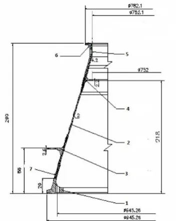
Fig 1 Cross sectional view of Base structure
II. RELATEDWORK
The reduction of mass for any structure is a biggest task for the structural engineers. Weight reduction and improved damage tolerance characteristics were the prime drivers to develop new family of materials for the aerospace/aeronautical industry. There are many methods to reduce the mass of any structure. In them replacing the material of the structure with light weight material is mostly preferred. Here we have considered replacing of the material with the light weight material which is a fibre reinforced plastic material. The fibre reinforced plastics is a composite material which is made of complete fibre, light in weight and strong in nature. CFRP is the most famous material used in aerospace industry since its properties matches with the properties of the alloys used in the construction of the aerospace structures. So the CFRP is considered to replace the metallic alloys in the structure.
III.FINITEELEMENTMODELLINGANDANALYSIS
A. MODELLING
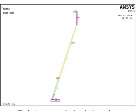
Fig 2: Areas created using the key points B. Element Selection
Composite material models can be modelled in ANSYS using the specialized elements called layered elements. After building the model using these elements, any structural analysis like static, non linear static, Eigen buckling, modal analysis, dynamic analysis etc., can be performed. For modelling the base structure the SOLSH 190 element is used which is a combination of Solid and shell elements. After the completion of the modelling the material is selected and the layups are given for each volume separately. The material selection and the lay up for the composite structure are shown in the tables 1 and 2 given below.
Part number Name of the part Material selected
1 Base of structure Aluminium alloy 7010 T73651
2 CFRP Main structure CFRP M55J/914
3 Outer lip CFRP M55J/914
4 Inner lip CFRP M55J/914
5 Titanium insert Ti alloy TI-6AL-4V
6 Top lip CFRP M55J/914
7 Bottom stiffener CFRP M55J/914
Table1: Parts of base structure with material used
Name of the section Part number Section number Lay up
CFRP Main
Structure 2 1 [#02/02/+45/-45/04]s
Outer Lip 3 2 [#02/902/02/+45/-45/02/90/02]s
Inner Lip 4 3 [#02/0/90/0/+45/-45/04]s
Top Lip 6 4 [#02/0/90s/#0]s
Stiffener 7 5 [#02/903/+45/-45/90/0/90/0]s
C. Boundary Conditions
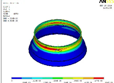
The elements are checked for free edges, distortion level and shell normal consistency to ensure reliable results after the analysis. The spacecraft mass is considered as 600kg and is applied at the top surface of the base structure by fixing the bottom surface. The interface ring is held from the bottom by a clamp band which interfaces the ring with launch vehicle payload adapter. So the interface ring that is the bottom surface of the structure is fixed. The boundary conditions applied on the base structure is shown in the figure 4 below.
Fig 4 Applied boundary conditions on the base structure
D. Analysis
The linear static analysis is performed on the base structure by varying the material with height. The insert of the structure whose height is 48mm and made of Ti alloy is considered. The insert material is varied with height the deformation and stresses are calculated for each. By performing the linear static analysis on the base structure varying material with height, it is observed that as the thickness increases the deformation decreases. For each thickness the deformation is observed to be varying drastically with the difference in material with heights. The total deformation of the structure for the thickness of 8mm is shown in fig 5.
IV.RESULTSANDDISCUSSIONS
The results obtained from the linear static analysis performed on the base structure are compared with each case for different thicknesses. The deformation and the stress are compared for each.
A. Deformation
By comparing the values of deformation in the tabular column shown in table3 indicates that the deformation for the structure with material combination of Ti and CFRP is less than that of the deformation for the structure with individual materials. Thickness Total Titanium (1) Total CFRP (2) CFRP till 278mm (3) CFRP till 266mm (4) CFRP till 254mm (5)
6 0.334 0.34 0.258 0.258 0.264
Table 3: Total deformation varying with the different material for each thickness value
B. Stress
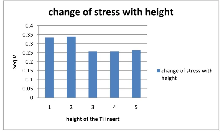
The Von Mises stress is often used to determine whether an isotropic and ductile metal will yield when subjected to a complex loading condition. This is accomplished by calculating the von Mises stress and comparing it to the material’s yield stress, which constitutes the Von Mises Yield criterion. The graph 1 below shows the Von Mises stress acting on the base structure. By observing the graph, we can say that the stress acting on the structure 8mm thickness and insert material as combination of Ti and CFRP is less than that of all the other structures.
Graph 1: Variation of Von Mises stress with material 0 0.05 0.1 0.15 0.2 0.25 0.3 0.35 0.4
1 2 3 4 5
Se
q
V
height of the Ti insert
change of stress with height
C. Mass
The mass of the base structure can be reduced to reduce the mass of the complete spacecraft. By replacing the complete base structure with CFRP the mass is reduced by 5% for the base structure. By decreasing the mass, the performance can be increased for the spacecraft. But the insert cannot be replaced with the composite material, so only the insert is remained as metal. The material is changed at the insert at different heights which varies the stresses acting on it. The change of mass of the base structure with change in material is shown in the table 4 and the graph 2 shows the graphical representation of change in mass of the base structure.
Existing design
Optimized Design
CFRP including Ti
insert and aluminum
base
CFRP till 254mm
CFRP till 266mm
CFRP till 278mm
CFRP with only aluminum
base
8.54 Kg 7.76 Kg 7.57 Kg 7.60 Kg 7.53 Kg 7.39 Kg 7.02 Kg
Table4: Estimated mass for each material change in the insert
Graph2: Reduction of mass with change in material
V. CONCLUSION
part can be replaced by the composites and instead of using the complete composite or complete metallic, combination can be used which is reducing mass of the base structure.
REFERENCES
[1] K.K Sairajan, P.S. Nair, “Optimum design of a composite base structure of a spacecraft” Altair CAE Users Conference 2005, August 11-13 [2] Devika Venu, Dr. Alice Mathai, Prof. Jayasree Ramanujan, “ Finite Element Analysis of Interface ring of a Rocket Launcher” IJIRSET, Vol2,
Issue 3, March 2013, ISSN: 2319-8753.