Study on the improved recuperator design used in the direct helium-turbine power
conversion cycle of HTR-10
Wu Xinxin1), Xu Zhao2)
1)Professor, INET, Tsinghua University, Beijing, P.R.China (xinxin@mail.tsinghua.edu.cn) 2)Graduate Student, INET, Tsinghua University, Beijing, P.R.China
ABSTRACT
Recuperator is one of the key devices in the direct helium-turbine cycle of 10MW High Temperature Gas cooled Test Reactor (HTR-10GT). In the former research, a recuperator had been already designed for HTR-10GT. Due to the space limitation in PCU vessel, the recuperator needs to be improved to reduce its volume. The purpose in this study is to create a new compact high-effective recuperator which has a smaller volume than the former one by using fins on the heat exchange plate. This paper presents the main characteristics, structural peculiarity and the thermal-hydraulic analysis of the improved recuperator.
INTRODUCTION
10MW High Temperature Reactor (HTR-10) has been reached to full power in 1, 2003. According to the developing tendency of technology on international high temperature gas cooled reactor and request to develop high temperature gas cooled reactor of China in future, the project, HTR-10 Second Phase, was brought forward to add the power conversion unit with direct gas-turbine cycle in the HTR-10 SG’s pressure vessel. HTR-10 incorporated with helium-turbine is an advanced concept with great prospects, which is theoretically based on the closed Brayton cycle with recuperating, intercooling and precooling processes. It is expected to have favorable safety features and economic competitions. Recuperator is one of the key equipments of this system and its main function is intended to ensure high effectiveness of the gas-turbine cycle by means of helium heating at the core inlet due to helium heat at the turbine outlet. It guarantees reliable operation over full power range and in all typical modes including startup and shutdown modes. In the former research, a recuperator had been already designed for HTR-10GT. Due to the space limitation in PCU vessel, the recuperator needs to be improved to reduce its volume. A new compact high-effective recuperator has been studied with a smaller volume than the former one by using fins on the heat exchange plate.
THE REQUIRED MAIN TECHNICAL CHARACTERISTICS AND BRIEF DESCRIPTION OF DESIGN
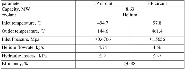
The required main technical characteristics of the recuperator in the nominal operation mode (at 100% electric power) are presented in Table 1.
Table 1. The Required Main Technical Characteristics
parameter LP circuit HP circuit
Capacity, MW 8.63
coolant Helium
Inlet temperature, ℃ 494.7 97.8
Outlet temperature, ℃ 144.6 461.4
Inlet Pressure, Mpa ≤0.6766 ≤1.5656
Helium flowrate, kg/s 4.74 4.56
Hydraulic losses,KPa ≤13 ≤5.7
Efficiency, % ≥0.88
The type of the recuperator is a vertical plate heat exchange with finned surface. The helium circulates in the recuperator on the basis of counter-flow scheme. Helium with the temperature of 494.7℃ and pressure of 0.6766 MPa from the turbine goes to the recuperator low-pressure path and transfers heat to high-pressure path helium, leaves the recuperator
with the temperature of 144.6℃ and enters the precooler. Helium with the temperature of 97.8℃ and pressure of 1.5656 MPa from the HPC goes to the recuperator high-pressure path, leaves the recuperator with temperature of 461.4℃
The STRUCTURE OF RECUPERATOR
Fig.1 shows the structure of recuperator. The recuperator is based on 36 heat exchange elements. Each of them in the cross section has a shape of equal lateral trapezoid. The heat exchange elements are located around the circular ring, being adjacent to each other by lateral sides. The heat exchange element consists of two heat exchange plates, a separation plate, finned matrices, casing, and elements for channel closing.The heat exchange plate is made of 0.4 mm thick sheet bent in the cross section like zigzag. The bends form alternating longitudinal channels for circulation of heat exchange fluids. At the same time, fins are fixed on the exchange plates both sides of the channels turned to the trapezoid bases, and these channels are closed at the ends of the heat exchange element. The channels turned to the internal separation plate are open at ends of the heat exchange element. There are two openings for fluid passage on the upper and lower sections of the casing on the sides of trapezoid bases. Lower ends of heat exchange elements are fixed in the circular ring of the collection header in the high-pressure cavity. The heat exchange elements are surrounded by distribution and collection headers in the low-pressure cavity on the internal and external sides of the circular ring in the places where low and upper openings are located.
12
5
3 2
§Ў
280
5
6 7 4 1
§Ў
0.25 5
B
(2:1)
§Ў §Ў
1.5
0.4
2.1
(8:1)
B
THERMOHYDRAULIC ANALYSIS
The purpose of the analysis is definition of the recuperator heat transfer coefficient, hydraulic resistance and required heat transfer surface during plant operation at 100% electric power.
Main Geometrical Characteristics of Recuperator
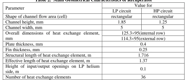
Input data for the recuperator structural thermohydraulic analysis are the required characteristics in the plant operating mode at 100% electric power. The important factors influencing selection of the recuperator dimensions are the limitation on the amount of hydraulic losses in the high-pressure and low-pressure helium paths and the limitation on dimensions determined by the space limited in PCU vessel. The main geometrical characteristics of the recuperator are presented in Table 2.
Table 2. Main Geometrical Characteristics of Recuperator
Value for Parameter
LP circuit HP circuit Shape of channel flow area (cell) rectangular rectangular
Channel height, mm 1.85 1.25
Channel width, mm 5 5
125.3×95(internal row) Overall dimensions of heat exchange element,
mm 114.3×95(external row)
Plate thickness, mm 0.4
Fin thickness, mm 0.25
Structural length of heat exchange element, m 1.716 Effective length of heat exchange element, m 1.37 Height of input/output openings on LP helium
side, m 0.1
Number of heat exchange elements 36
The Calculation Methodology Used in Thermal Analysis
The thermal analysis is performed in one-dimensional approximation for the counter-flow scheme of coolants. The main calculation equations are thermal balance equation and heat transfer equation.
1 p1
(
in out)
2 p2(
out in)
Q GC T
=
−
T
=
G C t
−
t
h
Q
=
KF t
Δ
Heat transfer coefficient based on the high-pressure area:
1 2
1
wK
R
R
R
=
+
+
Where:
2 1
1 1 1
1
A
R
A
α η
=
×
2 2 21
R
α η
=
2 w wA
R
δ
λ
=
Fin efficiency is caculated assuming the fin to be rectangular, using the classic fin efficiency formula [1]. Average logarithmic temperature head
log
(
) (
)
ln
inlet outlet outlet inlet
inlet outlet
outlet inlet
T
t
T
t
t
T
t
T
t
−
−
−
Δ
=
⎛
−
⎞
⎜
−
⎟
⎝
⎠
,The convective heat transfer coefficients on both circuits are calculated at constant thermo-physical properties of the coolants, equal to average values along the length of the heat exchange surface.
The active length of the heat exchange surface is used in the thermal analysis. The active length means the distance between the centres of the input and output openings on the low pressure side. The convective heat transfer coefficients used in finned matrices are defined according to the following formula[2]:
p
C
V
St
α
=
× × ×
ρ
2 / 3
Pr
St
= ×
j
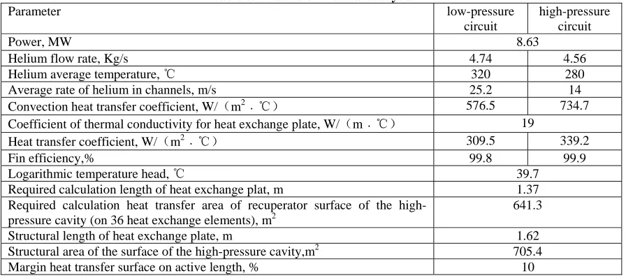
−The results of recuperator thermal analysis results are presented in Table 3.
Table 3. Results of thermal analysis
Parameter low-pressure circuit
high-pressure circuit
Power, MW 8.63
Helium flow rate, Kg/s 4.74 4.56
Helium average temperature, ℃ 320 280
Average rate of helium in channels, m/s 25.2 14
Convection heat transfer coefficient, W/(m2﹒℃) 576.5 734.7
Coefficient of thermal conductivity for heat exchange plate, W/(m﹒℃) 19
Heat transfer coefficient, W/(m2﹒℃) 309.5 339.2
Fin efficiency,% 99.8 99.9
Logarithmic temperature head, ℃ 39.7
Required calculation length of heat exchange plat, m 1.37 Required calculation heat transfer area of recuperator surface of the
high-pressure cavity (on 36 heat exchange elements), m2
641.3
Structural length of heat exchange plate, m 1.62
Structural area of the surface of the high-pressure cavity,m2 705.4
Margin heat transfer surface on active length, % 10
Hydraulic Analysis
The purpose of the hydraulic analysis is to determine the pressure losses on high- and low-pressure helium paths with account of input and output sections.
From the point of view of hydraulics, both on high- and low-pressure circuits the recuperater may be divided into three sequential sections: supply section; recuperator heat exchange element; removal section.
On the low-pressure path the input section includes the outlet of eight nozzles (150 mm in diameter) into the distributing header and distribution along 36 heat exchange elements, and the outlet section – outlet of the recuperator cavity into the collecting header and then into the removal tubes (five tubes of 190 mm in diameter). Along the high-pressure path, the inlet section is crack-type holes on the ends at the entrance to the heat exchange elements. The outlet section is the outlet from the heat exchange elements into the high-pressure header and then into eight tubes of 150 mm in diameter.
At each section the helium circulation path is divided into the characteristic hydraulic elements. The resistance of each element at averaged helium physical parameters is calculated. The total pressure losses are determined by combining the losses on the individual path elements.
The hydraulic resistance of friction during flow in the heat exchange element channels is calculated as per the following formula:
2
u
2
lossesP
ξ
⎛
⎜
ρ
⋅
⎞
⎟
Δ
= ⋅
⎜
⎟
⎝
⎠
Friction resistance coefficient
fr h
l
d
ξ λ
=
⋅
For the stabilised laminar flow the friction coefficient in the rectangular channel
λ
fr depends on the ratio of a/b sides of the channel and the Reynolds’ number, for the low-pressure side:/
2.7
a b
=
,and the high-pressure side:
/
4
a b
=
for both sides of low- and high-pressure respectively:
Re
64
fr
λ
×
=
The local resistances coefficients in the removal and supply nozzles and on the sections of the helium lateral inlet/outlet into the heat exchange element on the low-pressure side are determined by the following formula[5].
Inlet resistance:
2 2 1
1
(1
)
2
cG
p
σ
K
ρ
Δ =
−
+
Outlet resistance:
2 2
2 2
2 2
(1
)
2
2
eG
G
p
σ
K
ρ
ρ
Δ =
−
−
The result of the hydraulic analysis is listed in table 4.
Table 4. Results of Hydraulic Analysis
Helium path section Hydraulic losses, Pa Low-pressure circuit:
- helium supply section 275.68 - heat exchange element 4794.42 - helium removal section 65.09
- total losses 5135.19
High-pressure circuit:
- helium supply section 216.67 - heat exchange element 4696.31 - helium removal section 28.23
- total losses 4941.2
CONCLUSIONS
After the improvement, the heat transfer coefficient of the new recuperator is larger than the former one. It changes from 251W/( m2⋅℃) to 339.2W/( m2⋅℃). So the structural area of the surface decreases from 945 m2 to 705.4 m2. The length of the improved heat exchanger is 0.93 m shorter than the previous design, and the number of heat exchange elements has been reduced to 36 from 38. Much spaces bas been saved for setting other equipments and systems. However, the hydraulic losses on both side is not increases. The results is significant to the project of HTR-10GT.
NOMENCLATURE
Q=quantity of heat transferred via the heat exchange surface
G1, G2= helium flow rate on sides of low-pressure and high-pressure, respectively CP1, CP2= helium specific heat on sides of low-pressure and high-pressure, respectively Tin, Tout= gas temperature at the inlet, outlet on low-pressure side
tin, tout= gas temperature at the inlet, outlet on high-pressure side K= heat transfer coefficient
F= heat exchange surface
Δth= average logarithmic temperature head
α1,α2= convective heat transfer coefficient from low-pressure and high-pressure helium, respectively η1, η2= fin efficiency of the low-pressure path and high pressure path, respectively
R1, R2 = thermal resistance[2] of convective heat transfer on the side of low-pressure and high-pressure helium based on the high-pressure area, respectively
RW = thermal resistance of heat exchange plate based on the high-pressure area; δ= wall thickness
λw=wall thermal conductivity CP= helium specific heat V=flow velocity of helium ρ= helium density St= stanton number
j= factor, which can be decided by Reyonlds number Pr= Prandtl number
λ= helium thermal conductivity at average temperature dh= channel hydraulic diameter
Δplosses=hydraulic losses ξ=friction resistance coefficient ρ=helium average density u=average rate in the channel
λfr=linear friction resistance coefficient
l = channel length
dh= channel hydraulic diameter σ= ratio of flow area / max area
ρ1, ρ2= helium density in the supply and removal nozzles G= Mass flux density
Kc= inlet resistance coefficients Ke= outlet resistance coefficients
REFERENCES
1. Frank Kreith, Basic heat transfer, HARPER&ROW, PUBLISHERS, New York. 1980
2. Kays W M, London A L, Compact heat exchangers (second edition), New-York: Mc Grow-Hill Book Company, 1964 3. Codes for NPP equipment and piping strength analysis, ПНАЭГ-7-002-86
4. Rules for design and safe operation of NPP equipment and piping, ПНАЭГ-7-008-89
5. SHI Zhongmei, Heat exchanger theory and design, Southeast University Publishing Company,1989