Volume 2010, Article ID 306709,15pages doi:10.1155/2010/306709
Research Article
Performance Analysis of “WBC over DVB-H” Link Layer
Zhanlin Ji, Ivan Ganchev, and M´airt´ın O’Droma
Telecommunications Research Centre, University of Limerick, Limerick, Ireland
Correspondence should be addressed to Ivan Ganchev,[email protected]
Received 28 August 2009; Accepted 15 December 2009
Academic Editor: Yevgeni Koucheryavy
Copyright © 2010 Zhanlin Ji et al. This is an open access article distributed under the Creative Commons Attribution License, which permits unrestricted use, distribution, and reproduction in any medium, provided the original work is properly cited.
This paper presents two novel smart cross-layer error-control coding schemes for improving the error protection of service advertisements that are broadcast to mobile terminals on wireless billboard channels (WBCs) established over a digital video broadcast-handheld (DVB-H) infrastructure. These are the smart section erasure (SSE) and smart transport stream erasure (STSE) schemes, which are jointly executed by the link layer and service layer cross-layer algorithms. The new schemes are analysed and compared to existing schemes. The solution enables the “WBC over DVB-H” system to operate with good flexibility, and in a more reliable way and with greater throughput efficiency than the standard IP datacasting supported in DVB-H.
1. Introduction
Wireless billboard channels (WBCs) are novel infrastructural components of the emerging ubiquitous consumer wireless
world (UCWW) [1–5]. UCWW is particularly matched to
maximizing the efficient and economic use of the
mas-sive, and ever-growing, range of wireless communications interfaces, access networks’ communications services and teleservices. It is particularly in harmony with the thrust to realize the user-driven always connected and
best-served (ABC&S) communications paradigm [6,7]. In it, the
mobile user (MU) acts as a consumer and is identified by a personal, network-independent and location-independent, IPv6 address. The consumer is not constrained to any particular access network provider (ANP) and may use any available teleservice through any available access network that best matches consumer’s needs at any time or place. For the use of services an MU pays through a trusted third-party authentication, authorization, and accounting service provider (3P-AAA-SP). The service providers (xSPs)—ANPs, value-added service providers (VASPs), and teleservice providers (TSPs)—can benefit from simplicity of having a single business agreement with 3P-AAA-SP and from the easier entry in the wireless communications market in order to succeed, and so forth.
In UCWW maximizing the volume of consumer wireless transactions, and not the number of subscriber contracts,
is the primary business driver for service providers. The newly conceived WBC infrastructural component of UCWW aims to satisfy the requirement in this environment of facilitating the service providers “pushing” advertisements
and information about their service offerings to potential
consumers. Taking into account the potentially large number
of services already available, efficient and easy-to-implement
mechanisms for services’ advertisement, discovery, and asso-ciation (ADA), adapted to the terminal capabilities, user preferences, and user location, need to be developed for WBC.
A number of carrier technologies are suitable to carry the WBC dataset, for example, the digital audio broadcast (DAB), digital multimedia broadcasting (DMB), digital radio mondiale (DRM), digital video broadcast-handheld (DVB-H), multimedia broadcast/multicast service (MBMS), satellite DMB (S-DMB), digital audio radio satellite, and so forth. Among these technologies the DVB-H is an attractive solution due to its full support for IP datacasting
(IPDC). The IPDC over DVB-H [8,9] is a new European
Telecommunications Standards Institute’s (ETSI) standard
which enables effective distribution of digital content to mass
audiences. As commercial DVB-H services have already been rolled out, the market prospect of DVB-H devices seems very
bright [10].
The layered architecture of the designed “WBC over
WBC content server JSR 272 (broadcast API)
WBC-IPcast WBC
service layer
ADP UDP IP/IPsec v6
DVB-H encapsulator
User viewer JSR 272 (broadcast API)
WBC-IPcast ADP UDP IP/IPsec v6
DVB-H decapsulator
MPE-FEC encoder
MPE encap-sulator
Time slicer
MPE-FEC decoder
MPE decap-sulator
Time de-slicer
DVB-H modulator DVB-H demodulator
OFDM 2k 4k 8k OFDM 2k 4k 8k
WBC-SP node User node
WBC link layer (DVB-H)
WBC physical layer
(DVB-H)
Figure1: The “WBC over DVB-H” layered architecture.
of service advertisements in WBC is an important issue since even a single bit error (in an unprotected message) may result
in failure to decode a particular WBC data segment [11]. A
section erasure (SE) decoding algorithm based on a cyclic redundancy check (CRC-32) scheme is recommended in
the standard ETSI’s DVB-H implementation guidelines [8].
However, for certain applications the potential throughput
efficiency can be impeded enough since the multiprotocol
encapsulation-forward error correction (MPE-FEC) frame may be marked as incorrect even if it happens that some
self-contained parts of it are error-free. In [12,13], a transport
stream erasure (TSE) decoding scheme and two hierarchical erasure-plus-error Reed-Solomon (RS) decoding schemes were proposed in the link layer to improve reliability. The
hierarchical decoding schemes in [13] lead to complex
hardware design of the DVB-H link layer. In this paper, two new smart cross-layer encoding and decoding schemes— smart section erasure (SSE) and smart TSE (STSE)—for
improving the reliability and throughput efficiency of WBC
datacasting are proposed, analyzed, and compared to the existing schemes.
The rest of the paper is organized as follows.Section 2
provides an overview of the “WBC over DVB-H” link layer and describes the link layer’s encapsulation, encoding,
decapsulation, and decoding schemes.Section 3explains the
two new smart cross-layer encoding and decoding schemes.
Section 4focuses on the theoretical analysis, and Section 5
on a simulation to obtain performance results for “WBC over DVB-H” in a Rayleigh fading channel environment.
Section 6summarizes the conclusions.
2. “WBC over DVB-H” Link Layer
In 2004, the ETSI ratified the standard of DVB-H, which is an amendment of the digital video broadcasting-terrestrial
(DVB-T) standard [14] and takes into account the specific
properties of a typical portable mobile terminal (MT), such as limited battery-life, various signal environments, Doppler
effect, propagation loss of indoor reception, limited antenna
gain, and poor weather conditions. To enable an IPDC function, two new features were introduced into the DVB-H link layer, namely, time-slicing and MPE-FEC.
This is the platform for which we have designed a “WBC over DVB-H” implementation. In this, the WBC link layer acts as a bridge between the service layer (SL) and physical layer (PHY) for transforming the IP packets into transport stream (TS) packets, adding appropriate error protection and so forth, and performing the inverse operations at the receiver. An example of the three-layer encapsulation structure of “WBC over DVB-H” protocol data units (PDUs)
is presented inFigure 2.
2.1. Time-Slicing. In DVB-T, all channels are multiplexed
by means of an orthogonal frequency division multiplexing (OFDM) and broadcast in parallel. To receive data from a channel, MTs need to stay in active mode all the time, with no allowance made for the need to conserve battery power in the mobile unit. Responding to the normal MT requirement
of efficient use of battery energy—maximizing battery
WBC segment 1 Application
enabler sublayer
WBC segments
WBC segmentw
In
WBC service layer WBC link layer RS data Table (64) Application data Table (191)
1 191 192 255
ket Padding
CSIT
MPEG-2 TS packets · · ·
· · · CRC-32
184B IP packet (or parity section)
4B
WBC physical layer Off-time (Ot)
With this mechanism MT remains most of the time in
a sleep mode and becomes active only when atarget burstis
broadcast on air. A target burst is one likely to contain service description data of interest to the mobile user, as determined
by his/her profile stored on the MT. The off-time between
each burst is denoted by ETSI asOt(seconds) and the relative
minimum time to the beginning of the next burst from the start of the present MPE (or MPE-FEC) section being
received isdelta-t[8]. To successfully receive a data burst, MT
should become active a little bit before the scheduled arrival of the target burst. This is to allow for variation in the actual
arrival time from the scheduled arrival time due to the
delta-t jidelta-tdelta-terDj(10 ms by default) and thesynchronization-timeSt
(250 ms by default) [8].
The WBC burst duration is defined in [8] as
Bd= Bs
Br×(1−overhead)
, (1)
whereBsis the burst size (bits),Br is the burst bit rate (bits
per second), andoverheadis the overhead fraction resulting
from the TS packet and section headers.
By comparison with a constant bit rate (CBR) channel, the power saving when employing the time-slicing
mecha-nism could be calculated as in [8]:
whereCbdenotes the CBR (bits per second).
2.2. Multiprotocol Encapsulation-Forward Error Correction
(MPE-FEC). MPE-FEC is introduced in DVB-H to
compen-sating for the performance degradations in wireless fading channels. The MPE-FEC frame is constructed as a table consisting of 255 columns and a number of rows (256, 512,
768, or 1024; [8] andFigure 2). Each cell in the table contains
one byte. The 255 columns are divided in two parts: from 1st to 191st column–an application data table (ADT), and from 192nd to 255th column–a RS data table (RSDT). The IP packets are installed into the ADT column-wise, one by one. An RS code is used on each row of ADT for improving the link-layer error protection. Some parity columns are
punctured to achieve different MPE-FEC code rates. Usually
one DVB-H burst contains only one MPE-FEC frame. Each DVB-H burst carries a number of WBC segments.
2.3. Encapsulation and Encoding Algorithms. On the WBC
service provider’s (WBC-SP) side, the IP packets are cached on transition from the WBC service layer to the WBC logical link control (LLC) sublayer of the DVB-H link layer. When the number of IP packets in the cache becomes
sufficient to fill the ADT, the IP packets are encapsulated
into ADT in column-wise fashion, one by one. Than an RS (255,191) encoder runs on each row of ADT to generate 64 RS parity bytes, which are inserted into the corresponding FEC row. After the MPE-FEC frame is fully constructed, at
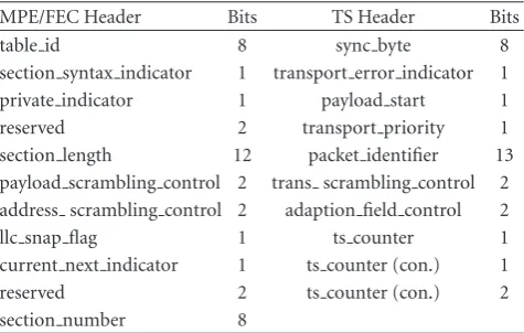
Table1: Parameters of MPE/FEC and TS Headers.
MPE/FEC Header Bits TS Header Bits
table id 8 sync byte 8
section syntax indicator 1 transport error indicator 1
private indicator 1 payload start 1
reserved 2 transport priority 1
section length 12 packet identifier 13
payload scrambling control 2 trans scrambling control 2 address scrambling control 2 adaption field control 2
llc snap flag 1 ts counter 1
current next indicator 1 ts counter (con.) 1
reserved 2 ts counter (con.) 2
section number 8
the medium access control (MAC) sublayer, each IP packet in ADT and each column of RSDT are extracted for adding a MAC overhead, that is, 12B MPE/FEC header and 4B
CRC-32 trailer (Figure 2). The resultant MPE/FEC data units
are segmented into an MPEG-2 transport stream (TS) for broadcasting over the channel. Each TS packet consists of 4B header and 184B payload, and is encoded at the physical layer by using an RS (204, 188) code for further error protection.
Compared with the standard DVB-H link layer, our “WBC over DVB-H” link layer uses an additional 8B smart correct segment index table (CSIT), which is inserted at the end of the last WBC segment’s padding area to help the
decoder operate in an efficient way. CSIT includes the size
of the erasure info table (EIT), used to store the decoding information, the number of WBC segments in one MPE-FEC frame, the advertisements delivery protocol’s (ADP) parameters, and so forth.
A description of the first 40 bits of the MPE/FEC header
and the 32 bits of the TS header is provided inTable 1.
2.4. Decapsulation and Decoding Algorithms. The
encapsula-tion and encoding schemes are stated in the DVB-H standard
[8]. The design of the decoding method, however, is open.
In [8], an SE decoding scheme is suggested as follows.
At theMAC sublayer, the MPE/FEC section is first generated
from the received TS packets, and a CRC-32 code verifies it. If verification is successful, the MPE/FEC section is marked as “reliable”; otherwise it is marked for “erasure”. Then the IP packet/parity section is extracted and together with the
CRC verification result is sent to the LLC sublayer. At theLLC
sublayer, the ADT/RSDT columns are generated from the
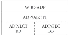
WBC-ADP ADP/ALC PI ADP/LCT
BB
ADP/FEC BB
Figure3: The ADP building block structure.
To improve error protection, in [13] a TSE scheme is
suggested. Compared with SE, at theMAC sublayerthe TSE
MPE/FEC section decoding does not depend on the CRC
scheme. It uses a bit indicator—transport error indicator
(TEI), located in the TS header—to identify whether the TS packet was or was not decoded successfully with the
RS(204,188) at the physical layer. If TEI =0, the decoding
was successful. If TEI=1, the decoding failed (this includes
packet IDentifier(PID) decoding failure and payload
decod-ing failure). At the LLC sublayer, the corresponding TS
packet position of EIT is filled with “0” or “1”, and the decoding scheme is the same as in SE. As the TS payload is smaller than the MPE/FEC section’s payload, the TSE scheme
outperforms the SE scheme [13].
3. Smart Cross-Layer Encoding and Decoding
Algorithms for “WBC over DVB-H”
3.1. Advertisements Delivery Protocol (ADP). The ADP
encoding and decoding are basic elements used in the smart cross-layer encoding and decoding algorithms for “WBC
over DVB-H” link layer [3, 15]. The core ADP elements
include building blocks (BBs) and protocol instantiation (PI). Two modified BBs—layered coding transport (LCT) and FEC—and one modified asynchronous layered coding
(ALC) PI were developed for ADP.Figure 3depicts the ADP
building block structure.
As the WBC segment is small in size, based on previous studies, the one-dimensional small-block RS codes are particularly well suited for ADP due to their characteris-tics, for example, good performance in correcting wireless burst errors, no “coupon collector problem”, and so forth,
[15].
The ADP decoding scheme includes packet erasure decoding (PED) and packet erasure plus byte error decoding (PE+BED) schemes.
Figure 4shows an example of the PED process. An 8kB WBC segment is first divided into 8 equal-size IP packets,
which are then encoded by an RS (n,k) algorithm (wheren=
10, is the number of encoding symbols per WBC segment;
k =8 is the number of source symbols per WBC segment).
This way the receiver can recover a WBC segment from any 8 (out of 10) encoding symbols received without errors.
The PE+BED scheme is explained in detail in [16].
3.2. Link Layer. Being not designed for WBCs with their
specific characteristics in mind, the SE and TSE decoding
processes are not efficient for direct use in WBCs. As one
DVB-H burst (MPE-FEC frame) usually contains several
WBC segments, even a single byte error in the MPE-FEC frame may cause a decoding failure. To improve the error protection in WBCs, the CSIT used by ADP for cross-layer decoding was developed.
The decapsulation process of the WBC smart cross-layer
decoding is similar to that described in Joki and Paavola [13];
that is, it maps into a smart SE (SSE) and a smart TSE (STSE) schemes.
The WBC smart decoding process, however, is different
as per algorithm.
(1) Try to decode each rowjof the MPE-FEC frame. In
case of failure, mark the undecoded rows and go to step 2.
(2) Initialize CSIT. Execute the following Algorithm 1
(w denotes the number of WBC segments in an
MPE-FEC frame,xdenotes the number of column(s)
occupied by each IP packet).
Comparing with SE and TSE decoding schemes, the new WBC smart cross-layer decoding schemes provide better error protection. On the other hand, due to the fact that the WBC smart decoding works with the ADP protocol, the time
complexity is increased fromO(k×l×x) toO(k×(n−k+l+
l×x)), wherelis the number of lost packets. This, however,
is acceptable because the complexity increases linearly. The functional model of the “WBC over DVB-H”
link-layer decoder is depicted inFigure 5.
3.3. Service Layer. To further improve the error protection,
the PE+BED algorithm runs at the bottom of the service layer.
Figure 6shows the WBC segment error rate (SER) as a function of the IP packet error rate (IPER) for PED and
PE+BED schemes in memoryless channel, where n = 10,
k = 8, and the IP packet length is 1024B. The results show
that the PE+BED scheme outperforms the PED scheme. On the MU side, the decapsulation and decoding scheme is selected automatically by MT based on the MT’s composite
capability/preference profile (CC/PP) [17]. MTs with very
limited capabilities should select the SE decoding algorithm, whereas MTs with reasonable computing capabilities should select the STSE decoding algorithm.
4. IPER and SER Analysis
IPER and SER are important criteria for measuring the decoding performance for “WBC over DVB-H” link layer. In this section, the theoretical analysis of IPER and SER is performed by means of a one-state loss model (i.e., the bit/byte error rate follows a uniform distribution).
Table 2lists the notations used in this section.
To simplify the analysis, similarly to [12] the size of the
IP packet is set toN =535 bytes (B) (i.e., close enough to
the standard value for N of 512). Each MPE-FEC column
Reciever
Figure4: A graphical representation of the ADP packet erasure encoding/decoding process.
in the link layer: fori=1to w
if there are “1s” in corresponding EIT columns, then
(a) extract i∗x∗n IP packets from the MPE-FEC frame, and
(b) decode with ADP in packet erasure mode. if a WBC segment is decoded successfully,
then
(a) encode the recovered WBC segment into IP datagrams with ADP packet erasure scheme, and
(b) fix the corresponding MPE-FEC cells and EIT table.
(c) try to run the RS algorithm on the MPE-FEC frame. end if
end if i=i+ 1
end for.
if EIT contains errors, fori=1to w
if IP(good)<k, fill the ADP header reserved area (r) with “1”.
endif endfor endif
forward IP packets to the service layer.
Algorithm1
whereas the last TS packet includes the corresponding 4B CRC-32 code.
4.1. Smart Section Erasure (SSE). In SSE, the probabilitypc
of a MPE column error occurring is
pc=1−
Table2: Parameter definitions.
w Total number of WBC segments in MPE-FEC frame
d Number of RSDT columns in MPE-FEC frame
p Bit error probability in binary symmetric channel (BSC)
pb Byte error probability in BSC
pc MPE column error probability in BSC
pt TS packet error probability in BSC
N Number of rows of MPE-FEC frame
M Number of columns of MPE-FEC frame being filled
As w WBC segments are installed in one MPE-FEC
frame, then
M=w×n+d. (4)
With the SE decoding scheme, in order to reconstruct the
MPE-FEC frame, at leastw×ncolumns (out ofM) must
be received with no errors. Then the MPE-FEC error rate (MFER) can be obtained as
MFER=1−
The IPER after the SE decoding can be obtained as
IPER=1−(1−MFER)1/M. (6)
Then the corresponding SER can be obtained as
SER=1−(1−IPER)k. (7)
MAC sublayer
LLC sublayer
TS packets
Finish
Store TS packet in TS buffer table
Create empty MPE-FEC frame, EIT based on CSIT
Generate MPE/FEC section, extract MPE/FEC section’s payload, update MPE-FEC, EIT with MU
pre-defined decapsulating algorithm
No
Yes
No
Yes End MPE-FEC frame
fully built?
MPE-FEC, EIT building process finished
Decode MPE-FEC frame with MU pre-defined
algorithm
Done for all TS packets?
IP packets
ADP PED WBC service
layer
Figure5: The “WBC over DVB-H” link-layer decoder’s functional model.
In the service layer, an ADP PE+BED algorithm is run if the received WBC segment contains errors. After completing the decoding process at the service layer, the service layer (SL) byte error rate can be obtained as
pbSL=1−
j=n
i=k+(n−k)/2
Cij
1−pbLL
i
pbLLj−i. (9)
Then the corresponding IPER is
IPERSL=1−
1−pbSL
N
, (10)
and the final SER can be obtained as
SERSL=1−
j=n
i=k
Ci
j(1−IPERSL)iIPERSLj−i. (11)
4.2. Smart Transport Steam Erasure (STSE). In STSE,
consid-ering that each TS packet contains 188 bytes, the probability
ptis
pt=1−
1−pb
188
. (12)
With the SE decoding scheme, in order to reconstruct the
MPE-FEC frame, at leastw×nTS packets must be received
0
ADP PED scheme ADP PE + BED scheme
Figure6: WBC SER as a function of IPER for ADP PED and for ADP PE+BED.
in the final 180 rows, respectively. Then the MFER can be obtained as
The TS packet error rate (TSPER) after the SE decoding can be obtained as
TSPER=1−
Then IPER and corresponding SER can be obtained as
IPER=1−(1−TSPER)3;
SER=1−(1−TSPER)3k.
(15)
After running the smart cross-layer decoding algorithm (ADP PED) on top of the link layer, SER, TSPER, IPER, and the corresponding byte error rate can be obtained as
SERLL=1−
In the service layer, after completing the decoding process
(PE+BED), the byte error rate is the same as in (9), and the
corresponding TSPER is:
TSPERSL=1− STSE in LLC STSE in SL STSE in LLC STSE in SL (b)
Figure7: The comparison of decoding schemes on (a) IPER and (b) SER (In both figures the left three graphs correspond to the SE and two SSE results).
The final IPER and SER can be obtained as:
IPERSL=1−(1−TSPERSL)3;
4.3. Comparison of Decoding Schemes. Figure 7 illustrates
IPER and SER as a function of the byte error rate (pb) for
n=10 andk=8.
The analytical results show that the CRC-based decoding schemes (SE, SSE) are not better than the TS-based schemes (TSE, STSE) because the TS packet is shorter than the
MPE/FEC section and thus more efficient for decoding.
10−2 10−1 100
20
0 40 60 80 100
Run length (number of TS packets)
Bad runs (top red line) Good runs
(a)
10−2
10−3 10−1 100
20
0 40 60 80 100
Run length (number of TS packets)
Bad runs
Good runs (top green line) (b)
Figure8: The observed probability distributions of good runs and bad runs in “WBC over DVB-H” with SNR of (a) 12 dB and (b) 15 dB. (PHY parameters: 16-QAM, CR=1/2, 4K OFDM, GI=1/4; WBC is assumed be Rayleigh distributed with AWGN).
the number of erasure/error columns can be corrected by ADP PED at the LLC sublayer and by PE+BED at the service layer.
5. Simulation Analysis of “WBC over DVB-H”
Link Layer in Rayleigh Fading Channel
5.1. Two-State Run Length Model (2SRL). Previous studies
have shown that errors in wireless channels occur in burst
mode due to the multipath propagation [18–20]. In [21],
a finite-state Markov model (FSMM) to represent Rayleigh fading channels in noninterleaving coding systems is
intro-duced. In [12], a finite-state run length model for simulating
the TS packet error behavior in a multipath channel environ-ment is presented, but the model’s parameters are obtained
by unbiased estimators. In [22], a two-state run length model
(2SRL) for analyzing the throughput in fading channels is proposed. However, the details of the fading channel and the manner of obtaining the parameters of the model are not explained. Despite the fact that the Rayleigh fading channel with a central chi-square distribution is known to be a flexible model that provides a definable number of degrees of freedom to experimental fading channel measurements
for outdoor environments [23], there are very few studies
for 2SRL over a central chi-square distribution Rayleigh channel. This subsection will focus on the received signal envelope having a central chi-square distribution and will use 2SRL to analyze the physical-layer TS packets outputting behavior.
The 2SRL model was developed from the two-state
Markov model (2SMM) [22]. The difference is that 2SMM
is concerned with the state transition probability, whereas 2SRL is concerned with the run-length probability. There are two probability distribution functions (PDFs) in 2SRL used for statistical analysis: a good run length probability
distributionfg(m) and a bad run length probability
distribu-tion fb(m). With these two PDFs, the TS packets good/bad
outputting can be easily generated. Figure 8 shows both
PDFs for different average values of the signal-to-noise ratio
(SNR), namely, 12 dB and 15 dB. The channel is assumed to be Rayleigh with additive white Gaussian noise (AWGN). The results demonstrate that by using basic curve fitting techniques (CFT), each PDF (in logarithmic scale) can be
approximated as a linear function (dash line).Figure 8also
demonstrates that fg(m) and fb(m) can be approximated by
a single geometric distribution function. Thus in “WBC over DVB-H”, 2SMM is used to approximate 2SRL.
The 2SMM model transition matrix is defined in [22] as
=
⎛
⎝1−b b
g 1−g
⎞
⎠, (19)
whereb andg are the transition probabilities. The
steady-state probability is
πsteady state=
πg,πb
=
g b+g,
b b+g
The average number of good states can be obtained as
whereas the average number of bad states can be obtained as
Xb=
Then the run length distributions of 2SRL can be
calculated by using the 2SMM parametersg,pe(G),b,pe(B)
andB, respectively.
5.2. 2SRL Parameters in “WBC over DVB-H”. The
probabil-ity densprobabil-ity function of a central chi-square distribution is
defined in [23] as
wherer denotes the received SNR in “WBC over DVB-H”
physical layer (r ≥ 0); σ2 is the variance of the Gaussian
scattering component; ndenotes the number of degrees of
freedom;Γ(·) denotes the Gamma function.
To get instantaneous SNR per symbol’s PDF [24],
p(r)dr= fγdγ, γ=r2TS
whereTSis the symbol time,σn2is the power spectral density
(PSD) of the noise which is equal toN0/2, andγis the average
SNR per symbol.
Then PDF of SNR per symbol can be obtained as
fγ
The cumulative distribution function (CDF) of (24) is
FR(r)
wherevis the speed of movement of the user terminal, fcis
the carrier frequency, andcis the speed of light. The expected
number of times per unit interval (also known as the level crossing rate) that the received signal passes downward across
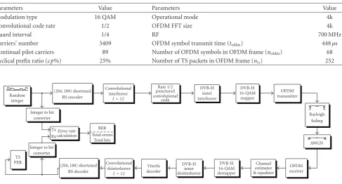
Table3: PHY Testbed’s Parameters.
Parameters Value Parameters Value
Modulation type 16 QAM Operational mode 4k
Convolutional code rate 1/2 OFDM FFT size 4k
Guard interval 1/4 RF 700 MHz
Carriers’ number 3409 OFDM symbol transmit time (tofdm) 448μs
Continual pilot carriers 89 Number of OFDM symbols in OFDM frame (nofdm) 68
Cyclical prefix ratio (cp%) 25% Number of TS packets in OFDM frame (nts) 252
Random integer
Integer to bit converter
(204, 188) shortened RS encoder
Integer to bit converter TS
PER
(204, 188) shortened RS decoder
Figure9: The “WBC over DVB-H” Matlab PHY Testbed.
To represent the time-varying behavior of a central chi-square fading WBC channel, the received SNR was quantized
with thresholdsγt. Thenπg,πbwere obtained as
The transition probabilitiesg andb were approximated
by the level crossing rate, the average number of TS packets
per unit interval (Tp), and{πg,πb}, as follows:
Finally, the error probabilities in state G and B were
obtained as described in [21]:
pe(G)=
from the “WBC over DVB-H” physical layer (PHY) simu-lation testbed, which is described in the next subsection.
5.3. “WBC over DVB-H” PHY Simulation Testbed. A “WBC
over DVB-H” PHY simulation testbed (Figure 9) was built
using Matlab with parameters shown inTable 3.
The testbed was designed based on the
ETSI-EN-300-744 standard [14]. The transmitter first generates a 252×
10−2
10−3 10−1 100
12
11 11.5 12.5 13 13.5 14 14.5 SNR (dB)
IP
ER
SE SSE in LLC SSE in SL
TSE STSE in LLC STSE in SL (a)
10−2
10−3 10−1 100
12
11 13 14 15
SNR (dB)
IP
ER
SE SSE in LLC SSE in SL
TSE STSE in LLC STSE in SL (b)
10−2
10−3 10−1 100
12
11 13 14 15 16
SNR (dB)
IP
ER
SE SSE in LLC SSE in SL
TSE STSE in LLC STSE in SL (c)
Figure10: The IPER simulation results for “WBC over DVB-H”: (a)fD=10 Hz; (b) fD=40 Hz; (c)fD=80 Hz.
code rate. During the interleaving step, for every 12096 bits, a block-based inner bitwise interleaving algorithm followed by a symbol interleaving algorithm is used to provide extra reliability. During the mapping and modulation steps, all data contained in one OFDM frame is modulated by a modulation algorithm. During the channel step, the output of modulation is first filtered by a chi-square fading algorithm and AWGN is added to it. The receiver processes the data in reversed order.
With the physical layer parameters obtained from the
testbed, the average number of packets per unit interval (Tp)
can be calculated as follows
Tp=tofdm×nofdm×
1 +cp%
nts .
(42)
5.4. Simulation Results. With the calculated values of 2SMM
parameters, the run length probability distributions fg(m)
and fb(m) of 2SRL can be calculated. Thus the 2SRL can
10−2
10−3 10−1 100
12
11 13 14 15
SNR (dB)
SER
SE SSE in LLC SSE in SL
TSE STSE in LLC STSE in SL (a)
10−2
10−3 10−1 100
12
11 13 14 15 16
SNR (dB)
SER
SE SSE in LLC SSE in SL
TSE STSE in LLC STSE in SL (b)
10−2
10−3 10−1 100
12
11 13 14 15 16
SNR (dB)
SER
SE SSE in LLC SSE in SL
TSE STSE in LLC STSE in SL (c)
Figure11: The SER simulation results for “WBC over DVB-H”: (a) fD=10 Hz; (b) fD=40 Hz; (c)fD=80 Hz.
The IPER and SER simulation results for SE, SSE, TSE,
and STSE are shown in Figures10and11, respectively. The
analysis of these results is as follows.
The Doppler Effect. As can be seen from the results,
IPER/SER worsen when the Doppler frequency increases, especially for the SE scheme. To get IPER/SER below 1% (WBC datacasting requirement), the received signal value should be increased about 0.5–1 dB for TSE schemes and 1.5–
2.5 dB for SE schemes for fD =80 Hz comparing with fD =
10 Hz.
The Section-Based and TS-Based Effect. As the TS packet is
smaller than the IP packet, a byte error in a TS packet will not mark the corresponding IP packet in error; thus the performance of TSE and STSE is better than SE and SSE. The results show that IPER/SER of the TS-based algorithms can gain 1-2 dB comparing with the section-based algorithms.
The Smart Cross-Layer Decoding Effect at the Link Layer. At
with SE/TSE when fD =10 Hz, and about 1-2 dB when fD=
80 Hz. The results also show that in order to get IPER/SER below 1%, the new STSE scheme can gain 2 dB comparing
with SE when fD=10 Hz and 3.5 dB whenfD=80 Hz.
The Smart Cross-Layer Decoding Effect at the Service Layer.
With the use of the ADP PE+BED decoding scheme, the IPER/SER at the service layer can gain additional 0.5–1 dB comparing with the IPER/SER at the link layer.
6. Conclusion
The performance of the “WBC over DVB-H” system can benefit from DVB-H’s time-slicing and multiprotocol encapsulation-forward error correction (MPE-FEC) fea-tures. This DVB-H’s IPDC system design facilitates WBCs sharing bandwidth resources with other DVB-H services. This should help smooth the WBC standardization process. It also facilitates further actions to improve error protection
of the WBC information, over and above that offered by
MPE-FEC which itself is designed for particularly difficult
reception situations.
Considering the commercial importance of the WBC ser-vices it is likely a high QoS will be required than the presently foreseen IPDC audio and video services. This paper has addressed techniques to improve error protection. Here the development of two novel smart cross-layer coding schemes based on the section erasure decoding and transport stream (TS) erasure decoding has been described. Based on an analysis of the error rate and on simulations using a wireless Rayleigh fading channel with received signal envelope having a central chi-square distribution, an approximation of the performance improvement has been obtained. A two-state packet-level run length model (2SRL) was introduced to evaluate the output statistics of MPEG-2 TS packets in a DVB-H fading environment. The results have confirmed that the newly proposed smart cross-layer decoding schemes can improve the error protection for the “WBC over DVB-H” system, over the MPE-FEC alone.
Acknowledgment
This publication has been supported by the Irish Research Council for Science, Engineering and Technology (IRCSET) and the Telecommunication Research Centre, University of Limerick, Ireland.
References
[1] M. O’Droma and I. Ganchev, “Towards a ubiquitous con-sumer wireless world,”IEEE Wireless Communications Maga-zine, vol. 14, no. 1, pp. 52–63, 2007.
[2] P. Flynn, I. Ganchev, and M. O’Droma, “Wireless billboard channels: vehicle and infrastructural support for advertise-ment, discovery and association of UCWW services,” in
Annual Review of Communications, Vol. 59, pp. 493–504, International Engineering Consortium, Chicago, Ill, USA, 2006.
[3] Zh. Ji, I. Ganchev, and M. O’Droma, “Performance evaluation of ‘WBC over DVB-H’ system,”IEEE Transactions on Con-sumer Electronics, vol. 55, no. 2, pp. 754–762, 2009.
[4] Zh. Ji, I. Ganchev, and M. O’Droma, “Building a ‘WBC over DVB-H’ software testbed,” in Proceedings of the 13th IEEE International Symposium on Consumer Electronics (ISCE ’09), pp. 769–772, Kyoto, Japan, May 2009.
[5] M. S. O’Droma and I. Ganchev, “Enabling an always best-connected defined 4G wireless world,” in Annual Review of Communications, Vol. 57, pp. 1157–1170, International Engineering Consortium, Chicago, Ill, USA, 2004.
[6] M. O’Droma, I. Ganchev, G. Morabito, et al., “Always best connected enabled 4G wireless world,” inProceedings of the 12th IST Summit on Mobile and Wireless Communications, pp. 710–716, Aveiro, Portugal, June 2003.
[7] I. Ganchev, M. S. O’Droma, M. Siebert, et al., “A 4G generic ANWIRE system and service integration architecture,”ACM SIGMOBILE Mobile Computing and Communications Review, vol. 10, pp. 13–30, 2006.
[8] ETSI, “Digital Video Broadcasting (DVB); DVB-H Implemen-tation Guidelines,” ETSI TR 102 377, V1.4.1, 2009.
[9] M. Kornfeld and G. May, “DVB-H and IP datacast—broadcast to handheld devices,”IEEE Transactions on Broadcasting, vol. 53, no. 1, pp. 161–170, 2007.
[10] X. Yang, J. Vare, and T. J. Owens, “A survey of handover algorithms in DVB-H,” IEEE Communications Surveys & Tutorials, vol. 8, no. 4, pp. 16–29, 2007.
[11] Zh. Ji, I. Ganchev, and M. O’Droma, “Efficient collecting, clus-tering, scheduling, and indexing schemes for advertisement of services over wireless billboard channels,” inProceedings of the 15th International Conference on Telecommunications (ICT ’08), pp. 225–230, Saint Petersburg, Russia, June 2008. [12] J. Paavola, H. Himmanen, T. Jokela, J. Poikonen, and V. Ipatov,
“The performance analysis of MPE-FEC decoding methods at the DVB-H link layer for efficient IP packet retrieval,”IEEE Transactions on Broadcasting, vol. 53, no. 1, pp. 263–275, 2007. [13] H. Joki and J. Paavola, “A novel algorithm for decapsulation and decoding of DVB-H link layer forward error correction,” inProceedings of the IEEE International Conference on Commu-nications (ICC ’06), vol. 11, pp. 5283–5288, Istanbul, Turkey, June 2006.
[14] ETSI, EN 300 744, “Digital Video Broadcasting (DVB); Framing Structure, Channel Coding and Modulation for Digital Terrestrial Television,” V1.6.1, January 2009.
[15] Zh. Ji, I. Ganchev, and M. O’Droma, “Reliable and efficient advertisements delivery protocol for use on wireless billboard channels,” inProceedings of 12th IEEE the International Sym-posium on Consumer Electronics (ISCE ’08), pp. 1–4, Algarve, Portugal, April 2008.
[16] Zh. Ji, I. Ganchev, and M. O’Droma, “‘WBC over DVB-H’ testbed design, development and results,”EURASIP Journal on Wireless Communications and Networking, vol. 2010, Article ID 769683, 18 pages, 2010.
[17] G. Klyne, F. Reynolds, C. Woodrow, et al., “Composite Capa-bility/Preference Profiles (CC/PP): Structure and Vocabular-ies,” W3C Recommendation, 2004, http://www.w3.org/TR/ CCPP-struct-vocab/.
[18] P. Dent, G. E. Bottomley, and T. Croft, “Jakes fading model revisited,”Electronics Letters, vol. 29, no. 13, pp. 1162–1163, 1993.
[19] E. N. Gilbert, “Capacity of a burst-noise channel,”The Bell System Technical Journal, vol. 39, pp. 1253–1265, 1960. [20] C. Xiao, Y. R. Zheng, and N. C. Beaulieu, “Novel
channels,”IEEE Transactions on Wireless Communications, vol. 5, no. 12, pp. 3667–3678, 2006.
[21] Q. Zhang and S. A. Kassam, “Finite-state markov model for rayleigh fading channels,”IEEE Transactions on Communica-tions, vol. 47, no. 11, pp. 1688–1692, 1999.
[22] J. McDougall and S. Miller, “Sensitivity of wireless network simulations to a two-state Markov model channel approxima-tion,” inProceedings of the IEEE Global Telecommunications Conference (GLOBECOM ’03), vol. 2, pp. 697–701, San Francisco, Calif, USA, December 2003.
[23] J. G. Proakis, Digital Communications, McGraw-Hill, New York, NY, USA, 4th edition, 2001.
[24] A. Goldsmith,Wireless Communications, Cambridge Univer-sity Press, Cambridge, UK, 2005.