© 2015, IRJET.NET- All Rights Reserved
Page 9
CRASH ANALYSIS FOR ENERGY ABSORPTION OF FRONTAL RAILS OF A
PASSENGER CAR
Raymond Joseph
1, Dr. M.A. Kamoji
21
M.Tech student (Design Engineering), Mechanical Engineering, K L E Dr. M S Sheshagiri College of Engineering
and Technology, Belgaum, Karnataka, India
2
Professor, Mechanical Engineering, K L E Dr. M S Sheshagiri College of Engineering and Technology, Belgaum,
Karnataka, India
---***---Abstract –
This paper presents the Finite ElementAnalysis of the frontal rails of a passenger car. Front rails will connect between Front bumper and Dash Toe pan. They are one of the structural members which will absorb high energies in frontal impact, so that impact energy won’t transmit to driver/passengers. A rigid barrier is modeled to collide with the left frontal rail. The rail is assigned with steel material. After providing the necessary interactions and performing meshing, the whole model is run for dynamic explicit code using ABAQUS 6.11 PR3. The graph results for Artificial Strain Energy, Kinetic Energy, Internal Energy and Total Energy are obtained and are compared with that of standard square tube. It was found that Internal Energy increased with time, Kinetic Energy decreased with time and Total Energy of the system remained the same. Then the specific energy absorption (SEA) is calculated using the same analysis for steel and aluminium for two different velocities i.e. at 20 mph and 30 mph. As a part of energy absorbing criterion, SEA of aluminium was better at both impact velocities.
Key Words:
Frontal rails, ABAQUS 6.11, Finite
Element Analysis and Specific Energy Absorption
(SEA).
1. INTRODUCTION
Passenger cars are a major mode of transport in the developed as well as in the developing countries. Therefore the accidents caused due to passenger cars are also significantly on the rise. In all types of crash accidents, about 30 % of the total numbers of accidents are frontal crash case. Therefore, measures to improve passenger vehicle passive safety performance in crash to reduce injury and death of passengers during a crash to the maximum has become an important subject of research. Current car body structures and light trucks include two major categories: body-over-frame structure or unit-body structure. The body-over frame structure of a passenger
car or a sport utility vehicle consists of vehicle body, frame, and front sheet metal.Unit-body structure vehicles combine the body, frame, and front sheet metal into a single unit which is constructed from stamped sheet metal and are assembled by spot welding.Steel is the material typically used in manufacturing the structure of vehicle. Only very few expensive cars vehicle’s bodies are made from aluminium or composite materials.
1.1 Introduction to the Frontal Rails
The frontal rails are an integral part of the crumple zones which form the front energy absorbing area. Front rails will connect between Front bumper and Dash Toe pan. They are one of the structural members which will absorb high energies in frontal impact, so that impact energy won’t transmit to passengers/ driver. Figure 1 shows the frontal rails.
Fig -1: Frontal rails
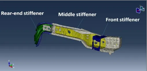
The frontal rails are welded with stiffeners inside it. As the name suggests, stiffeners are required to increase the rigidity of the component just to the required level. Figure 2 shows the stiffeners used inside the frontal rails.
© 2015, IRJET.NET- All Rights Reserved
Page 10
2. IMPACT ANALYSIS OF FRONTAL RAILS FOR
FRONTAL CRASH
The explicit dynamic analysis for the frontal crash case is conducted on ABAQUS 6.11 PR3. After meshing is
Table 1: Properties of steel and aluminium
Property Steel Aluminium
Density(ρ) 7890 Kg/m3 2700 Kg/m3 Modulus of
elasticity(E) 210 GPa 68.9 GPa
Poisson’s ratio(ν) 0.3 0.33
Yield stress(σy) 215 MPa 145 MPa
Table 2: Effective plastic strain data for steel
Plastic strain Stress(MPa,)
Table 3: Effective plastic strain data for Aluminium
Plastic strain Stress(MPa,)
0.0 145
0.08 186
Fig -3: Rigid impactor placed in front of the frontal left rail.
The boundary condition ENCASTRE is applied to the nodes where the frontal rail is attached to the adjacent front fender. This boundary condition restricts the displacement and rotation of the applied nodes in all three directions. The boundary condition DISPLACEMENT/ROTATION allows the displacement of the rigid barrier only in on direction, i.e. only in the X- direction.
Displacement/rotation in any other direction is strictly prohibited.
The impactor is meshed in ABAQUS 6.11 PR3. R3D A 4-node 3-D bilinear rigid quadrilateral element is used. The approximate global size applied is 50.
The frontal rail is meshed in HYPERMESH v.10 pre-processing tool. A combination of three noded trias (S3R 3-node triangular shell, finite membrane strains) and a four noded quad (S4R 4-node shell, reduced integration, and finite membrane strains) elements are used. The meshing criteria are displayed in table 4.
Table 4: Meshing criteria
No Meshing criteria Allowable value
1 Minimum mesh
3. RESULTS AND DISSCUSSION
For Steel
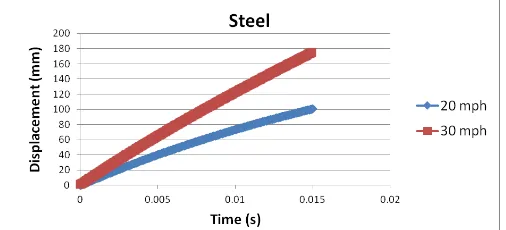
The current work is intended to perform dynamic explicit analysis on the passenger car frontal rails with steel and aluminium at two different velocities, i.e. at 20 mph and 30 mph. Therefore the corresponding parameters like Artificial Strain Energy, Internal Energy, Kinetic Energy, Total Energy and displacements are studied. Further, for each case the Specific Energy Absorption is also calculated. When the barrier hit the frontal rails at 20 mph the displacement observed was 100 mm. Again, when the same simulation was carried out for 30 mph the displacement observed was 174.8 mm. From the graph, it is observed that with higher impacting velocity, larger is the deformation of the frontal rails. Figure 4 shows the same.
© 2015, IRJET.NET- All Rights Reserved
Page 11
Fig -5: Frontal rails before simulation
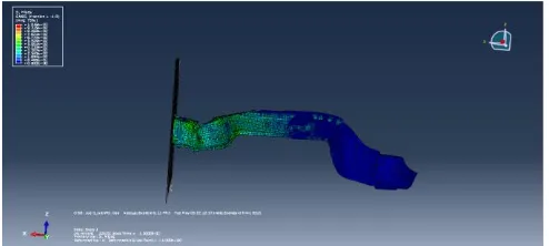
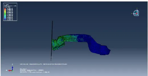
Figure 5 shows the shape of the component before impact analysis. Whereas Figure 6 and Figure 7 shows frontal rails after simulation for 20 miles per hour and 30 miles per hour.
Fig -6: Frontal rails after simulation for 20 mph
Fig -7: Frontal rails after simulation for 30 mph
3.1 Calculation of Specific energy absorption
(SEA) for steel
For comparison, the energy absorption capacity of specimens is a criterion that defines the mean collapse load and specific energy absorption (SEA). Specific energy absorption (SEA) is calculated by dividing the area under the load–displacement curve by the column mass [2].
Where, P is the load, δ is the displacement and M is the column mass.
At 20 mph,
At 30 mph,
For Aluminium
When the barrier hit the frontal rails at 20 mph the displacement observed was 122 mm. Again, when the same simulation was carried out for 30 mph the displacement observed was 189.7 mm. From the graph, it is observed that with higher impacting velocity, larger is the deformation of the frontal rails. Figure 8 illustrates the same.
Fig -8: Displacements using aluminium as material
The shape of frontal rails before simulation is shown in Figure 9. Whereas Figure 10 and Figure 11 shows the frontal rails after simulation for 20 mph and 30 mph.
© 2015, IRJET.NET- All Rights Reserved
Page 12
Fig -10: Frontal rails after simulation for 20 mph
Fig -11: Frontal rails after simulation for 30 mph
3.2 Calculation of Specific energy absorption (SEA) for Aluminium:
For comparison, the energy absorption capacity of specimens is a criterion that defines the mean collapse load and specific energy absorption (SEA). Specific energy absorption (SEA) which is given in equation is calculated by dividing the area under the load–displacement curve by the column mass.
At 20 mph,
At 30 mph,
Table 5 and Table 6 shows the displacement and Specific Energy Absorption (SEA) for steel and aluminium at 20 mph and 30 mph. It can be seen that the displacement and SEA of aluminium is greater than that of steel.
Table 5: Comparison of displacement of steel and
Table 6: Comparison of SEA of steel and aluminium
Material used for frontal rail
SEA (KJ/Kg ) at
20 mph 30 mph
Steel 0.4249 0.655
Aluminium 0.597 0.8913
4 CONCLUSION
The present work is aimed at carrying out dynamic explicit analysis on the frontal left rails of a passenger car. The analysis is carried out for two different materials and at two different velocities, i.e. at 20 mph and 30 mph. Further the graph results for internal energy, kinetic energy total energy where obtained which were found to be in good agreement with the standard model. As a part of energy absorbing criterion, the Specific Energy Absorption (SEA) was also found. The Specific Energy Absorption of steel at 20 mph is 0.4249 KJ/Kg and at 30 mph was found to be 0.655 KJ/Kg. Similarly, the Specific Energy Absorption of aluminium at 20 mph is 0.597 KJ/Kg and at 30 mph was found to be 0.8913 KJ/Kg.
Since from the results, aluminium shows better energy absorption characteristics, it is recommended that the frontal rails of an automobile passenger car be produced with aluminium material. Along with the above said benefits, the aluminium also boasts of being considerably lighter, thus gaining advantage on better acceleration and speed of the car. Added to it is the advantage of better fuel economy which is the playing card in today’s competitive passenger vehicle market. Also, with hybrid technology and electric vehicles paving the way for future, where
[1] A.A.A. Alghamdi, “Collapsible impact energy absorbers:
an Overview” Thin-Walled Structures, Elsevier,
October 2000
© 2015, IRJET.NET- All Rights Reserved
Page 13
[3] H H. Hooputra; H. Gese; H. Dell; H. Werner, “Acomprehensive failure model for crashworthiness simulation of aluminium extrusions” International Journal of Crashworthiness (08 July 2010)
[4] A. Deb, M.S. Mahendrakumar, C. Chavan, J. Karve, D. Blankenburg, S. Storen, “Design of an aluminium-based vehicle platform for front impact safety” International Journal of Impact Engineering (26 June 2004)
[5] Ahmed Elmarakbi n, YeeXinLong, JohnMacIntyre, “Crash analysis and energy absorption characteristics
of S-shaped longitudinal members” Thin-Walled
Structures, Elsevier (13 April 2013)
[6] A.G. Mamalis *, D.E. Manolakos, M.B. Ioannidis, D.P. Papapostolou, “Crashworthy characteristics of axially statically compressed thin-walled square CFRP composite tubes: experimental”, Composite Structures 63 (2004), Elsevier
[7] Shujuan Hou, Qing Li, Shuyao Long, XujingYang,Wei Li, “Design optimization of regular hexagonal thin-walled columns with crashworthiness criteria”, Finite Elements in Analysis and Design 43 (2007) 555 – 565, Elsevier, (15 February 2007)