R E S E A R C H
Open Access
Combined transmit beamforming and
channel-aware scheduling for interference
mitigation in femtocells
Alexis A Dowhuszko
1*, Mika Husso
1and Jyri Hämäläinen
1,2*Correspondence: [email protected]
1Department of Communications
and Networking, Aalto University, P.O. Box 13000, FI-00076 Aalto, Finland
Full list of author information is available at the end of the article
Abstract
The introduction of femtocells in mobile networks gives rise to new co-layer and cross-layer interference scenarios. To mitigate interference, several approaches have been proposed in the literature including, e.g., transmit beamforming (TBF), power control, and fractional frequency reuse. In this article, we present an interference mitigation approach that relies on a low-rate control channel between the victim terminal and the interfering femto access point (FAP). The proposed method combines both, practical TBF schemes and simple one-bit channel-aware scheduling algorithms. We show that the proposed method can be effectively used not only to mitigate interference among FAPs, but also to balance user rates in adjacent cells with small signaling overhead.
Introduction
Eventhough the concept of the home base station (HBS) was introduced as early as 1996 [1,2] and Alcatel was planning to commercialize it in 2000 [3], it took until around 2007– 2008 for the research and concurrent business activities to gain real momentum. The fem-tocell term, then, was adopted around 2005 for a standalone, self-configuring low-power base station [4]. Currently, femtocells constitute an important study topic with a signifi-cant body of accumulated research, receiving wide industry support at the same time.
Adding the femtocell component into the existing macrocellular networks raises a number of technical challenges related to, e.g., timing and synchronization, spectrum allocation and interference management [5]. Eventhough mobile operators may in princi-ple allocate a separate carrier for femtocell operations (eliminating thereby the cross-layer interference problem), constraints related to spectrum availability and costs often make this approach unattractive or unfeasible. However, even in presence of a dedicated band for femto-femto operation, interference still remains as a serious problem: the uncoor-dinated nature of femtocell deployments generates a great variability in the quality of service (QoS) that the users perceive in the network.
The problems of both, cross-layer and co-layer interference in an heterogenous network that combines multiple layers have been widely addressed in academic research. While the first publications [5-7] concentrated on characterizing and quantifying the problem, more recent studies have typically focused on methods for interference coordination and mitigation utilizing different approaches to tackle the problem. In, e.g., [8,9], the authors
proposed the use of dynamic frequency re-use, whereas in [10,11] power control was uti-lized for downlink and uplink cross-layer interference mitigation purposes, respectively. In addition, contributions of [12-14] explored the use of transmit beamforming (TBF) methods for interference mitigation that rely on explicit channel state information (CSI) reports in the reverse channel (i.e., for FDD air interfaces), while [15] analyzed the use of a busy burst protocol to coordinate the selection of TBF vectors at neighboring cells when channel reciprocity holds (i.e., for TDD air interfaces). In [16], a scheduling method was presented for reducing macro-femto interference, and in [17,18] beamforming and scheduling were combined for inter-femtocell interference mitigation purposes. It is important to highlight that, within LTE-Advanced nomenclature, 3GPP standardization has given the name enhanced intercell interference coordination (eICIC) to categorize those techniques that are designed to mitigate interference in an heterogeneous network scenario. A good summary of them can be found, e.g., in [19] and references therein.
In this article, we present a low-rate feedback method for co-layer interference mitiga-tion and cell balancing in the downlink of a closed-access femtocell. Using a combinamitiga-tion of practical TBF methods and simple channel-aware inter-cell scheduling algorithms, we show that resources (i.e., degrees of freedom in the spatial and temporal domains) can be transferred from a cell operating in high SINR regime to a cell that is operating with low SINR. In other words, the proposed method is able to effectively balance the downlink data rate that is achieved at each cell, requiring only the presence of a low-rate uplink con-trol channel between the interfering femto access point (FAP) and the victim femto user equipment (FUE). We note that a similar method, known as enhanced codebook-based transmission, was presented in [20] and references therein as one potential solution for performance enhancements in single- and multi-cell LTE-Advanced networks. Neverthe-less, the main difference with our proposal lies in the fact that in a FAP, the number of associated FUEs is expected to be much lower than the number of potential candidates to be served in a macro base station. This limitation precludes the possibility of finding a best companion(for user pairing) andworst companion(for interference coordination) to be served simultaneously at each transmission time instant.
The rest of the article is structured as follows. Section ‘System model’ presents the general system and the adopted assumptions, the applied TBF schemes, and the channel-aware scheduling algorithms that are analyzed. Section ‘Theoretical analysis’ derives the theoretical formulas that are required to evaluate the performance of our proposed method, whereas Section ‘Performance analysis’ shows the corresponding results that were obtained (both, theoretical, and numerical ones). Finally, Section ‘Conclusions and discussion’ concludes the article and enumerates open issues that are suitable for future research study.
System model
This section presents the general system model and the assumptions that are adopted for the closed-access femtocellular system. The TBF schemes and the channel-aware scheduling algorithms are also introduced in this section.
Interference scenario and adopted assumptions
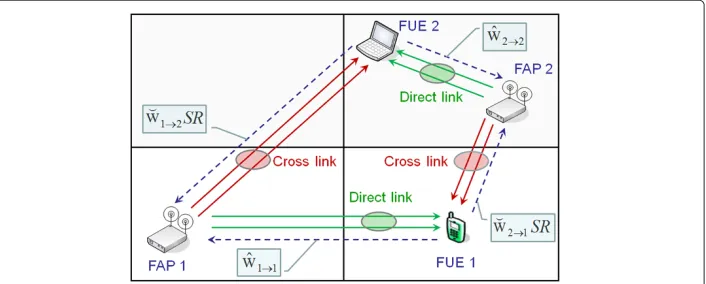
the TBF vectorwthat maximizes its received SINR. In addition, when experiencing high interference originated in a neighboring femtocell, we assume that each (victim) FUE has the chance to inform the TBF vectorwˇ that would minimize the received interference power when applied in transmission at the corresponding (interfering) FAP. Finally, each FUE can request the interfering FAP to temporarily stop transmission by issuing a silence request (SR) message. In order to convey this interference mitigation related feedback, we consider the existence of an additional low-rate reverse control channel between each victim FUE and the neighboring FAP that is responsible of the largest interference con-tribution. For an illustrative purpose, the general system model whenM=2 is presented in Figure 1.
The implementation of our interference coordination approach demands the exchange of control information between victim FUE and interfering FAP. In our system model, we consider that this signaling exchange is doneover the airin a single-hop fashion, relax-ing the requirement of havrelax-ing a backhaul femto gateway (FGW) connection that supports real time control message exchange using a two-hop approach (i.e., relaying the control information from serving to interfering FAP). Note that actually, 3GPP Rel. 10 supports an X2-like interface between FAPs. However, the information exchange over X2 is time constrained due to delay issues, especially when dealing with FAPs that belong to different closed subscriber groups (CSGs). Although it will take some years until Rel. 10 products become widely available in the market, the main limitation for using control messages over X2 is that the quality of this interface is not expected to improve considerably in the future (especially for residential customers that use xDSL connections as back-haul). Thus, standardizing effective over the air control mechanisms is important, to be able to implement interference coordination schemes within femtocell environments in a simple way.
Note that in our system scenario, we consider that both femtocells are located close to each other. Therefore, if we consider that a given victim FUE is experiencing strong interference from a neighboring FAP (in the direct-link), we can also assume that the signal strength in the reverse channel (i.e., from the victim FUE to the interfering FAP) will be also good enough to guarantee a proper exchange of control messages for interference coordination. Nevertheless, it is important to notice that all the analysis that is presented in this article does not preclude the use of a two-hop signaling scheme (e.g., (1) FUE 1→
FAP 1, (2) FAP 1→FAP 2) whenever a reliable backhaul interface between neighboring FAPs is available. Details of the feedback channel and the interference mitigation methods will be discussed in Sections ‘Transmit beamforming’ and ‘Channel-aware scheduling of silence periods’.
Adopted assumptions
We have adopted the following baseline assumptions regarding the general framework:
(A1) We analyze a two-cell scenario where an adjacent FAP creates downlink co-channel interference to the FUE of the reference cell. Transmission power in the FAPs is constant and handover between cells is not possible. In other words, CSG configuration is applied, but the FUE can establish a control connection to both, the serving and the interfering FAP unit.
(A2) There areM transmit antennas in both FAPs, and a single receive antenna in each FUE. The terminal can estimate signals from the different antennas of both, the serving FAP and the interfering FAP. Throughout this article, channel estimation is assumed to be perfect at the receiver side. The terminal can send a quantized feedback message to both femtocellular transceivers, including information for the antenna weight selection and SR messages. The impact of feedback delay and feedback errors is ignored.
(A3) Channel gains related to the different antennas of a given FAP are considered as independent and identically distributed (i.i.d.) complex zero-mean Gaussian random variables (RVs), while the mean received power is different for different FAPs. Fast fading corresponding to different FAPs is assumed uncorrelated.
Transmit beamforming
To implement TBF in a FDD system, a base station makes use of quantized CSI, encoded into a feedback message that is sent from the mobile terminal through a reverse control channel. In LTE, e.g., there is a physical control channel that carries feedback messages and may be used to convey CSI from the mobile terminal to the base station [21,22]. In our study, feedback words include short-term CSI, which is assumed to be available at the transmitter without errors or latency. For the analysis in the presence of feedback errors refer to, e.g., [23].
In an interference-free case, the received signal at the mobile terminalkis given by
rk=(hk→k·wk)sk+nk =
M
m=1
h(km→)kw(km)
sk+nk, (1)
whereMis the number of transmit antennas, sk is the transmitted complex baseband
symbol,hk→k=
h(1)k→k. . .h(kM→)k
is the channel gain vector between mobile terminalk and each transmit antennamof its serving base station (composed of zero-mean complex Gaussian coefficients),wk =[w(1)k . . .w(kM)] is the complex beamforming vector that the
serving base station applies, andnkrefers to zero-mean complex additive white Gaussian
noise with powerPN. Note that in our signal model, termnk reflects not only the effect
adjacent-channel interference originated in both, macro- and femto-layers of the hetero-geneous network). Sincenkgroups a large number of non-separable sources of
interfer-ence, it is treated as white Gaussian noise when performing decoding at the receiver side. Complex transmit weights are normalized such that||wk||2 = Mm=1|w(km)|2 = 1. We note that signal model (1) assumes a frequency flat fading channel. For a frequency selec-tive fading channel, the same signal model can still be used if the total bandwidth of the systemBis divided into sub-bands that have an approximately frequency flat response, and TBF feedback is provided for each sub-band separately.
We assume that there are two FAPs (denoted by indicesk=1, 2), each serving one FUE with equal transmit powerPTx=E{|sk|2}. Then, the achievable rates for bandwidthBare
given by
R1(w1,w2) = Blog2 1+
PTx|h1→1·w1|2
PTx|h2→1·w2|2+PN
, (2)
R2(w2,w1) = Blog2 1+
PTx|h2→2·w2|2
PTx|h1→2·w1|2+PN
, (3)
wherehk→lis the channel gain vector from FAPkto FUEl, whilewkis the corresponding
beamforming vector that the FAPkapplies in transmission. Note that in (2) and (3), the dominant interference originated in the neighboring femtocell is treated as an extra com-ponent of additive white Gaussian noise, simplifying the implementation of the decoder at the receiver side (i.e., no advanced signal decoding and/or interference cancelation tech-niques are considered for this purpose). Now, related to the selection ofw1andw2, we
introduce two basic beamforming strategies.
Egoistic and altruistic beamforming
Inegoistic beamforming, each FAP selects for transmission the beamforming vectorwˆ that maximizes the rate towards its own FUE. Correspondingly, a strategy in which the FAP applies the beamforming vectorwˇ that minimizes interference to the FUE in the neighboring femtocell will be referred to asaltruistic beamforming.
When both FAPs implement egoistic beamforming, the achievable rates for bandwidth Bare given by
R(ego/ego)1 (wˆ1,wˆ2) = Blog2 1+
PTx|h1→1· ˆw1|2
PTx|h2→1· ˆw2|2+PN
, (4)
R(ego/ego)2 (wˆ2,wˆ1) = Blog2 1+
PTx|h2→2· ˆw2|2
PTx|h1→2· ˆw1|2+PN
. (5)
On the other hand, when FAP 1 implements egoistic beamforming (i.e., applieswˆ1) and
FAP 2 altruistic beamforming (i.e., applieswˇ2), the equivalent equations for the achievable
rates become
R(ego/alt)1 (wˆ1,wˇ2) = Blog2 1+
PTx|h1→1· ˆw1|2
PTx|h2→1· ˇw2|2+PN
, (6)
R(alt/ego)2 (wˇ2,wˆ1) = Blog2 1+
PTx|h2→2· ˇw2|2
PTx|h1→2· ˆw1|2+PN
. (7)
As expected, the implementation of altruistic beamforming at FAP 2 makes FUE 2 to lose the beamforming gain (because the selection ofw2becomes independent ofh2→2). It
the latter case (i.e., combination of altruistic and egoistic beamforming in a two-femtocell scenario).
In order to link the study to practical systems, we have employed a simple TBF method (known as closed-loop mode 1) that resembles the one applied in HSDPA in presence of two transmit antennas [24]. A similar method has also been adopted in LTE and, although our method is not exactly the same, the performance difference between HSDPA closed-loop method and its LTE counterpart is negligible. In HSDPA, the mobile user defines the 1-bit (phasing) message that is reported to the serving base station at each time instant. The base station thus maintains the phase at the first antenna, and then adjusts the phase of the second antenna based on the sliding averaging over two consecutive feedback com-mands, see [25] for more details. Note that if the speed of the mobile user is low (or equivalently, the coherence time of the channel is large compared to the signaling delay), closed-loop mode 1 is equivalent to have error-free QPSK phasing information at the sec-ond antenna. In other words, we can assume that transmit beamforming weights are not affected by the signaling delay, taking the form√1
2
1ej(2n+1)π4
, forn=0, 1, 2, 3. In this article, we consider a generalized mode 1 withNphasing bits. Instead of stan-dard QPSK phasing (i.e., 2-bit mode 1), we analyze the equivalent mode 1 versions with N = 0, 1, 2 (phasing bits/antenna), to illustrate the gain that additional resolution in the phasing information provides. The full channel phase information case (i.e.,N → ∞) is also considered, to determine the performance upper bound for the scheme. In addi-tion, we shall discuss the problem of feedback bit allocation between scheduling and TBF. AlthoughN-bit phasing is not an optimal closed-loop method, it admits closed-form for-mulations for performance measures (e.g., the outage probability). As a consequence, it allows to obtain a better insight to the system performance, than the one that would be achieved through a pure computer simulation study.
Channel-aware scheduling of silence periods
In the proposed method, the scheduling decisions of silence periods (SPs) can be based on the strength and timing of the transmissions from the dominant interfering femtocell. Thus, whenever there are free time resources available in the interfering FAP, they can be used to provide periods of silence that improve the achievable rates of victim FUEs in adjacent cells. Scheduling of such interference free periods is implemented as follows:
• Victim FUE transmits a SR message to the interfering FAP whenever it experiences high levels of interference. To keep the analysis tractable, we consider that interfering FAP always grants a SP when requested.
• Victim FUE is able to select the best moment to send SR easily, if interfering FAP informs the availability of interference-free resources in time domain (e.g., percentage of time frames in which transmission could be stopped under request). We consider that victim FUE is able to monitor these messages, e.g., listening to the broadcast channel of the adjacent femtocell.
• If SRs are not received at interfering FAP, it does not need to issue a SP at that time frame.
1. Cross-link scheduling criterion, or 2. Direct-link scheduling criterion.
Cross-link scheduling criterion can be expressed as
||hk→l||2
E{||hk→l||2}
>γˆth(c) k=l, (8)
whereγˆth(c)is a threshold that can be selected based on the service requirements. As sec-ondary option, scheduling decisions can be made using own signal strength. Then, the victim FUE can request a SP from the interfering FAP when the communication link towards its serving FAP is strong, i.e.,
||hk→k||2
E{||hk→k||2}
>γˆth(d). (9)
Finally, if we desire to maximize cell edge performance (e.g., the 10th percentile of a cumulative distribution function), then we may send a SR when we experience a weak channel in our direct-link, i.e.,
||hk→k||2
E{||hk→k||2}
<γˇth(d). (10)
Eventhough the different SP scheduling criteria (8)–(10) are presented as functions of the normalized received powers in both, cross-link and direct-link, SPs can also be triggered as functions of the received SNR in both links. The latter case is simpler to implement in practice, since the SNR value of both links can be easily estimated (at FUEs) measuring the quality of the pilot signals that FAPs broadcast in downlink. Note that in this case, the precise value that the scheduling threshold should take will be also affected by the background noise power that the victim FUE experiences in reception (i.e.,PN).
In this article, we mainly aim at improving low SINR performance. Therefore, we shall focus onγˆth(c)andγˇth(d)as the scheduling thresholds. The analysis that forms the basis for the performance evaluation is carried out in the following section.
Theoretical analysis
The analysis in this section is done using the cumulative distribution function (CDF) of the received SINR as the performance measure. Later on, we extend the analysis to the CDF of the throughput of the FUEs. Note that part of these results has been presented in [26], where closed-form expressions for the received SINR of TBF methods were derived, without scheduling SPs according to channel conditions.
Cumulative distribution function for SINR of mode 1
Keeping in mind the computation of the received SINR, we first consider the RV
Z= X
assuming that RVsXandYare independent. In this situation, the CDF ofZis of the form
FZ(z)=
+∞
1
FX(zt)fY(t−1)dt=
+∞
0
FX[z(t+1)]fY(t)dt, (12)
wherefY(y)is the probability density function (PDF) ofY, whileFX(x)represents the CDF
ofX[27].
To derive the stochastic behavior of
ϒ(1)=
γ1→1|h1→1·w1|2
1+γ2→1|h2→1· ˇw2|2
, (13)
where
γk→l= PTx Lk→lPN
∀k,l (14)
is the mean received SNR for the link between FAPkand FUEl(assumed constant during the whole duration of the communication), whileLk→lrepresents the corresponding
dis-tance dependent path loss attenuation (i.e., long-term component of the fading channel), we need to compute formula (12) assuming
X=γ1→1|h1→1·w1|2, Y =γ2→1h2→1· ˇw22. (15)
Unfortunately, exact distribution functions forX andY are difficult to obtain in this situation. So, we make use of thechi-square(χ2) distribution approximations presented in [28]:
FX(x)=1−
1+Gγ2x
1→1
e− 2
x
Gγ1→1 x≥0, G=E{|h
1→1·w1|2},
fY(y)= gγ1
2→1e
− y
gγ2→1 y≥0, g=E{h
2→1· ˇw22}.
(16)
ExpectationsG andg are known as the beamforming gains (or coherent combining gains) of the TBF scheme, and can be interpreted as scaling factors that reflect the impact of incomplete CSI in the system. In case of mode 1, the beamforming gains admit closed-form expressions [29]
G=1+π
4aN, g=1− π
4aN, aN = 2N
π sin π
2N
. (17)
its variance). Note that when this value is rounded to the closest even integer, its use enables to derive closed-form expressions which estimate different performance indica-tors with excellent fitting to simulated values. Results presented in [26], e.g., are based on this approach.
In order to simplify notation in the following equations, we define
ν1=
γ1→1
γ2→1, ν2= γ2→2
γ1→2. (18)
Then, after some manipulations we obtain
Fϒ(1)(z)=1−e
− 2z
Gγ1→1
⎡ ⎢ ⎣
2zν1G
g
ν1G
g +2z
2+
1+ Gγ2z
1→1
ν1G
g ν1G
g +2z
⎤ ⎥
⎦. (19)
When the FAP 2 applies TBF for interference mitigation purposes in FUE 1, beamform-ing gain in the second femtocell vanishes since component channels sum up with random phases. In other words, the numerator of expression
ϒ(2)= γ2→2h2→2· ˇw2
2
1+γ1→2|h1→2·w1|2
(20)
becomes exponentially distributed with mean value dictated by factorγ2→2(i.e., there is no beamforming gain). The same situation takes place in the second term of the denom-inator of (20), since the TBF vector that the FAP 1 applies does not take into account the actual values of channel gains in the corresponding cross-link. After some manipulations, it is possible to see that
Fϒ(2)(z)=1−
ν2
ν2+z
e−
z
γ2→2 (21)
establishes the CDF expression for the SINR of the second femtocell user in this case. It is important to note that when both FAPs carry out TBF independently (i.e., egoistic beamforming without considering interference mitigation issues), the SINR expressions become
ϒ1= γ1→1|h1→1·w1|
2
1+γ2→1|h2→1·w2|2
, ϒ2= γ2→2|h2→2·w2|
2
1+γ1→2|h1→2·w1|2
. (22)
In this situation,
Fϒl(z)=1−e
− 2z
Gγl→l
⎡
⎣ 2zνlG
(νlG+2z)2+
1+ Gγ2z
l→l
νlG
νlG+2z ⎤
⎦ l=1, 2 (23)
results when settingg=1 in (19). The latter expression reduces to
Fϒl(z)=1−e− 2z
Gγl→l 1+ 2z
Gγl→l
l=1, 2 (24)
Scheduling of silence periods based on cross-link signal strength
In this section, we derive a closed-form expression to characterize the stochastic behav-ior of the received SINR when the inter-cell scheduling among femtocells is based on the strength of the interference link (i.e., the cross-link interference level). When com-bining TBF with a channel-aware scheduling of SPs according to (8), the CDF expression presented in (12) becomes
FZ(z)=
γˆth
0
FX[z(t+1)]fY(t)dt+FX(z)Pr
y>γˆth
z≥0, (25)
where different probabilistic models are used to approximate the stochastic behaviors of RVsXandY, according to the number of phase bitsNthat are used in the quantization set of the TBF scheme.
Single-antenna system (no channel phase information)
When the TBF scheme does not use any kind of channel phase information, the beam-forming weights that the FAPs apply in transmission become independent of actual channel states. As a consequence, the performance of a multi-antenna system in absence of channel phase information is equivalent to the one of a single-antenna system, where the RVsXandYare exponentially distributed (with no beamforming gain).
Based on the analysis presented in Appendix 1, we have
FZ(z)=
1−e−
z
γ1→1+
ˆ
γth
γ2→1
− γ1→1
γ2→1z+γ1→1e − z
γ1→1
1−e− ˆγth
z
γ1→1+γ21→1
,
(26)
where γˆth is the threshold that defines the SR condition in the cross-link (note that the super-index (c) has been omitted to simplify the notation). As expected, closed-form closed-formula (26) reduces to (21) (applying the corresponding substitution of indexes) when the threshold value in the cross-link is set high enough to guarantee a continuous transmission in the interfering femtocell (i.e., whenγˆth→ ∞).
It is important to highlight that, the performance of TBF in absence of channel phase information is only identical to the one of a single-antenna system from a theoretical perspective, or when the frequency responses of the channels arestrictlyflat. Since perfect frequency flat channels do not exist in practice, the incoherent superposition of the copies of the same signal received from the different elements of an antenna array will actually increase the delay spread of the equivalent channel (with respect to the one that would be obtained using only one transmit antenna). Such an approach, that may be useful to reap frequency diversity applying a proper channel coding scheme, lies beyond the scope of this article and is therefore not considered. Nevertheless, it just mentioned here to avoid a wrong interpretation of the concepts presented in this section.
Partial channel phase information
Based on the analysis presented in Appendix 1, it is possible to see that
Here, the precise values forGandgare given in (17), and depend on the number of phase bitsNthat the serving FAP and interfering FAP use, respectively, to identify the beamforming weights that should be applied in transmission.
Full channel phase information (asymptotic upper bound)
Before finishing this section, we identify the performance of our scheme when the channel phase information is reported to the transmitter without quantization. Note that the full channel phase information case gives the performance upper bound, and allows the pro-vision of a quantitative measure of the impact of channel phase information accuracy in the performance of the method. The main difference between the full and partial channel phase information case is that, in the former one, the stochastic behavior of the interfer-ing signal at the victim mobile user should be approximated as aχ2distributed RV with 1 degree of freedom. The fading figure value that allows us to arrive to this conclusion can be easily computed using the closed-form expressions derived in Appendix B of [28].
Based on the analysis presented in Appendix 1, it is possible to see that
FZ(z) = 1− 1+
is valid in this situation, providing the upper bound performance of the system when the number of phase bits becomes large (i.e., whenN → ∞).
Scheduling of silence periods based on direct-link signal strength
In this section, we derive a closed-form expression to model the received SINR at the victim FUE, when the inter-cell scheduling between femtocells is based on the strength of its direct-link (i.e., SRs are triggered if the strength of the victim’s direct-link is not good enough). When combining TBF with channel-aware scheduling of SPs according to (10), the CDF expression presented in (12) becomes
FZ(z)=FZ(z|X>γˇth) Pr
X>γˇth+FX(z|X≤ ˇγth)Pr
Note that the second term of (29) characterize the SINR at the victim FUE when the interfering FAP is providing a SP. So, the CDF that is presented in the second term of (29) is actually the one that models the received SNR from the serving FAP (i.e., the CDF of RVX, because there is no interference originated in the neighboring FAP in this case).
Single-antenna system (no channel phase information)
In absence of channel phase information, the stochastic behavior of the desired signal energy (i.e., RVX) and the co-channel interference (i.e., RVY) can be modeled as an expo-nentially distributed RV (see Section ‘Scheduling of silence periods based on cross-link signal strength’ for more details). Then, based on the analysis presented in Appendix 2, we have
Note that in the previous equation,γˇth represents the threshold that defines the SR condition in the direct-link. Again, super-index(d)is omitted to simplify the notation.
Partial channel phase information
In presence of partial channel phase information, the stochastic behavior of the desired signal energy (i.e., RVX) and the co-channel interference (i.e., RVY) can be approximated as aχ2distributed RV with 4 and 2 degrees of freedom, respectively (see Section ‘Schedul ing of silence periods based on cross-link signal strength’ for more details). Then, based on the analysis presented in Appendix 2, it is found that
FZ(z) = 1+
where the precise values for the beamforming gainsGandg depend on the number of phase bitsN that are used to identify the beamforming weights at both FAPs (i.e., the serving FAP and the interfering FAP).
Full channel phase information (asymptotic upper bound)
Then, based on the analysis presented in Appendix 2, it is possible to see that
is valid in this situation, providing the upper bound performance of the system when the number of phase bits becomes large (i.e., whenN → ∞).
Performance analysis
In this section, we analyze the performance of TBF when combined with SR-based channel-aware scheduling. To illustrate the performance in each case, we utilize the CDFs of the achievable spectral efficiency and the outage rates that are observed in the different situations.
Cumulative distribution function
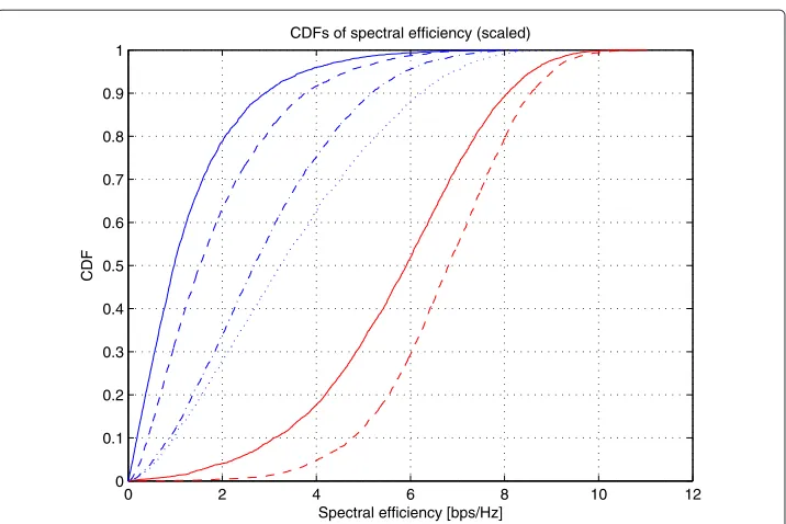
Since our aim is to equalize the rates of the two femtocells, let us first focus our atten-tion in an unbalanced user scenario. Therefore, we analyze the rate performance when the FUE in the first femtocell experiences a good signal strength (e.g.,γ1→1=15 dB), but at the same time the interfering signal originated in the second femtocell is also strong (e.g.,γ2→1=15 dB). Simultaneously, the FUE being served by the second femto-cell experiences a very good signal strength (e.g.,γ2→2=20 dB), but the strength of the interfering signal originated in the first femtocell is weak (e.g.,γ1→2 =0 dB). Note that the background noise powerPNis used as reference to measure the signal strengths in the
different links. As expected, in this case one user receives on average a significantly higher SINR as indicated by the solid lines in Figure 2 (i.e., when no TBF method is applied in transmission).
(dashed-0 2 4 6 8 10 12 0
0.1 0.2 0.3 0.4 0.5 0.6 0.7 0.8 0.9 1
Spectral efficiency [bps/Hz]
CDF
CDFs of spectral efficiency (scaled)
Figure 2 Rate cumulative distribution function for FUE 1 (blue) and FUE 2 (red) when 2-bit mode 1 is applied with different beamforming methods (no SP scheduling implemented).Interference scenario: γ1→1=15 dB (good signal),γ1→2=0 dB (weak interference),γ2→1=15 dB (strong interference), and γ2→2=20 dB (excellent signal). All cases:PNused as reference power. Solid: No TBF. Dashed: 2-bit mode 1 (FAP 1 ego/FAP 2 ego). Dashed-dotted: 2-bit mode 1 (FAP 1 ego/FAP 2 alt). Dotted:∞-bit mode 1 (FAP 1 ego/FAP 2 alt).
dotted line). Finally, FUE 1 can further reduce the gap when more bits are allocated for TBF purposes at both FAPs (FUE 1: dotted line FUE 2: solid line). It is important to high-light that even whenN → ∞, the interference generated at FAP 2 will not completely be nulled at victim FUE 1 (even when both signals are put exactly in phase opposition, some residual interference will remain since the transmit power cannot be adjusted individually at each antenna in our system model). We note that the closed-form expression for the performance of∞-bit mode 1 (dotted line) can be obtained from (28), setting the thresh-old value in the cross-link high enough to guarantee a continuous transmission in FAP 2. As expected, the same closed-form expression is obtained from (32) when the threshold value in the direct-link tends to zero.
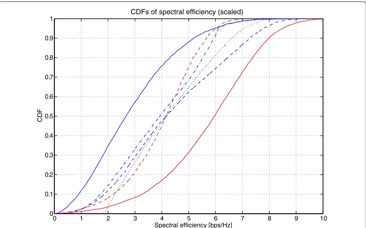
As seen in Figure 2, TBF can effectively narrow down the performance gap of the two users, but some difference still remains. Let us next look at the performance of the proposed scheduling method for closing the remaining gap. The solid lines in Figure 3 correspond to the situation in which 2-bit mode 1 altruistic beamforming has already been applied in FAP 2 for interference mitigation purposes at FUE 1. Now, using SR-based channel-aware scheduling we can provide to FUE 1 periods of low interference, increasing as a consequence the likelihood of experiencing higher instantaneous data rates. However, the selection of the applied threshold affects significantly the SINR region in which the (opportunistic) scheduling gain will appear.
0 1 2 3 4 5 6 7 8 9 10 0
0.1 0.2 0.3 0.4 0.5 0.6 0.7 0.8 0.9 1
Spectral efficiency [bps/Hz]
CDF
CDFs of spectral efficiency (scaled)
Figure 3 Rate cumulative distribution function for FUE 1 (blue) and FUE 2 (red) when 2-bit mode 1 is applied (FAP 1 ego/FAP 2 alt).Interference scenario:γ1→1=15 dB,γ1→2=0 dB,γ2→1=15 dB, and
γ2→2=20 dB. All cases:PNused as reference power. Solid curves: constant transmission (i.e., no scheduling). Blue curves: dashed (γˆth(c)), dashed-dotted (γˇth(d)), dotted(γˇth(ϒ )). Dashed red: all kinds of thresholds. Threshold selection: FUE 2 is 30% of time silent.
note that here, the selection of this specific activity factor is just for illustrative purposes (i.e., similar results are expected to be observed for different percentages of SRs). Study-ing the CDF regions in more detail it can be noticed that, settStudy-ing the threshold on the instantaneous received SINRγˇth(ϒ) provides the best performance at working regimes with low spectral efficiencies (i.e., at low outage probabilities). When implementing a channel-aware scheduling algorithm based on γˇth(ϒ), FUE 1 issues a SR in those time instants where its instantaneous received SINR is below a predefined threshold (like in previous cases, the threshold should be selected to guarantee the percentage of SPs that FAP 2 agreed in advance to support). On the other hand, the scheduling of SPs using the cross-link thresholdγˆth(c)provides a better performance at working regimes with high spectral efficiencies (i.e., at high outage probabilities). Finally, the implementation of a channel-aware scheduling algorithm that relies on the direct-link thresholdγˇth(d)provides the worst spectral efficiency over the whole CDF region. Note that the scheduling of SPs based onγˇth(ϒ)is included in this section for illustrative purposes, and its performance is solely evaluated based on numerical simulations. In addition, it is important to highlight that the spectral efficiencies in the second femtocell (i.e., red curves in Figure 3) are scaled by the corresponding activity factor that interfering FAP 2 agreed to support in advance with FAP 1.
Last but not least, let us look at the effect of the background noise-like interference on the performance of the algorithm that schedules SPs using the cross-link threshold
ˆ
γth(c). To carry out this analysis, we first select a value of background noise powerPN as
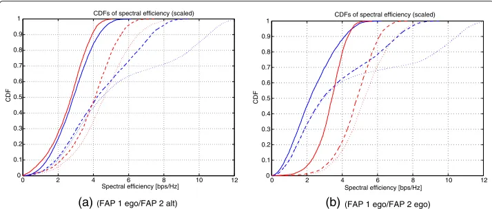
loss attenuations). Three cases are going to be analyzed:= 10 dB (strong background noise regime),= 0 dB (reference background noise regime), and = −10 dB (weak background noise regime). Figure 4a shows that the combination of TBF and channel-aware scheduling of SPs balances the rates effectively, except for the low background noise case (dotted line). This result is based on the fact that, as the system becomes more isolated (i.e., the background noise decreases), FUE 1 is able to receive very high SINR values during the SPs of FAP 2. The same behavior can be observed in Figure 4b, in which both FAPs apply an egoistic beamforming scheme. Nevertheless, it is evident that in the absence of interference mitigation gain (i.e., when both FAPs behave egoistically), the rates in the system do not remain balanced. In fact, equalizing the rates at the 50th per-centile would require the interfering femtocell to be silent in approximately 40–45% of the transmission time instants (depending on the background noise level).
Outage rate
In addition to the CDF approach presented in the previous section, we investigate the system performance in terms of outage rates. The outage rate of a system can be defined as:
Rout(Pout)=log21+γ (Pout), (33)
whereγ (Pout)is the SINR needed to achieve a given outage probabilityPout. The value ofγ (Pout), can be obtained by computing the solution for the following equation:
Pout=Prlog2(1+γ ) <Rout= γRout
0
fϒ(γ )dγ =Fϒ(γRout). (34)
Let us now look at the corresponding rates at outage probabilities 10 and 50%, when the threshold valueγth(orγˇth) varies. As seen in Figure 5, TBF mode 1 provides a significant
gain, but the relative gain decreases as the number of phase bits increases. Comparing
0 2 4 6 8 10 12
0 0.1 0.2 0.3 0.4 0.5 0.6 0.7 0.8 0.9 1
Spectral efficiency [bps/Hz]
CDF
CDFs of spectral efficiency (scaled)
(a) (FAP 1 ego/FAP 2 alt)
0 2 4 6 8 10 12
0 0.1 0.2 0.3 0.4 0.5 0.6 0.7 0.8 0.9 1
Spectral efficiency [bps/Hz]
CDF
CDFs of spectral efficiency (scaled)
0 0.5 1 1.5 2 2.5 3 3.5 4 0
0.5 1 1.5 2 2.5
Outage Rate for FUE 1 (bps/Hz)
Outage Rate for FUE 2 (bps/Hz)
Outage Probability 10 %
(a) 10-th percentile outage rate
0 1 2 3 4 5 6
0 1 2 3 4 5 6
Outage Rate for FUE 1 (bps/Hz)
Outage Rate for FUE 2 (bps/Hz)
Outage Probability 50 %
(b) 50-th percentile outage rate
Figure 5 Rate region for outage probability 10% and 50%.Red (o): Single-antenna. Green (): 1-bit mode 1. Blue ( ): 2-bit mode 1. Magenta ():∞-bit mode 1. Solid line:γˆth(c). Dashed line:γˇth(d). Interference scenario: γ1→1=15 dB,γ1→2=0 dB,γ2→1=15 dB, andγ2→2=20 dB. All cases:PNused as reference power.
the performance when using the threshold on the interference linkγˆth(c)and on the direct-linkγˇth(d), it can be concluded that the usage of cross-link threshold provides superior performance, except for the single-antenna case with 10% outage probability. In addi-tion, it is worth noting that in all cases, the rates achieved in both femtocells can be balanced by selecting an appropriate threshold value for the scheduling of SPs at the interfering FAP.
Related to the aim of balancing the data rates of the femtocells, let us next analyze the max-min outage rates when combining TBF and channel-aware scheduling (solid lines in Figure 6), i.e.,
Routmax−min=max ˆ
γth
minRout1 (γˆth),Rout2 (γˆth), (35)
−200 −15 −10 −5 0 5
0.5 1 1.5 2 2.5 3
Relative Noise Level (dB)
Max−Min Outage Rate for FUE 1 and FUE2
Outage Probability 10 % (Scheduling: Cross−Link)
−20 −15 −10 −5 0 5
0.5 1 1.5 2 2.5 3 3.5 4 4.5 5 5.5
Relative Noise Level (dB)
Max−Min Outage Rate for FUE 1 and FUE2
Outage Probability 50 % (Scheduling: Cross−Link)
(a) 10-th percentile outage rate (b) 50-th percentile outage rate
Figure 6 Max-min and min rates for outage probability 10% and 50%.Red (o): Single-antenna. Green (): 1-bit mode 1. Blue ( ): 2-bit mode 1. Magenta ():∞-bit mode 1. Solid line: TBF plus channel-aware scheduling usingγth(c)(all cases). Dashed line: only TBF (min outage rate). Interference scenario:
and the equivalent min outage rates in presence of TBF only (dashed lines in Figure 6), i.e.,
Routmin=minRout1 (γˆth→ ∞),Rout2 (γˆth→ ∞). (36)
Looking at the 10% outage probability case (i.e., Figure 6a) and 50% outage probabil-ity case (i.e., Figure 6b), we observe that the combination of TBF and channel-aware scheduling provides clearly the highest performance. Nevertheless, as the relative noise level increases, the gain from scheduling decreases as well. This decrease is significantly steeper than in the case where only TBF is applied. At the 50% outage rate level, the trends are very similar to the 10% case, but the rates are obviously higher. Still, it is important to note that already 1-bit mode 1 provides a remarkable gain with and without scheduling (using the case with no channel information as baseline) and could, therefore, significantly reduce outage in a practical system. In general, the more isolated the system is (i.e., the smaller is the background noise power) the better the proposed combination of TBF and channel-aware scheduling of SPs works.
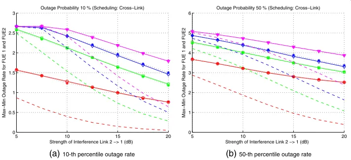
Finally, the interference link strength greatly affects the performance of the proposed TBF and scheduling methods, as illustrated in Figure 7. Eventhough the rates logically decrease as the interference link becomes stronger, the achievable gain from scheduling also increases while the beamforming gain is close to the same magnitude. However, it is worth noting that when the interference link is weak, allocating more than 1 phase bit for TBF does not result in a significant performance gain. Generally, as noticed in Figure 7, the proposed TBF and scheduling methods provide a substantial gain in terms of max-min outage rate although their relative effectiveness varies with the noise level.
Based on the performance analysis of this section, we can conclude that the proposed methods provide significant gains in all analyzed situations. In practical systems, however, there exists a tradeoff between the amount of signaling information and the achiev-able data rate in downlink. In general, the proposed 1-bit scheduling method provides very remarkable gains when the criterion is max-min rate. However, if we had focused
5 10 15 20
0 0.5 1 1.5 2 2.5 3
Strength of Interference Link 2 −> 1 (dB)
Max−Min Outage Rate for FUE 1 and FUE2
Outage Probability 10 % (Scheduling: Cross−Link)
5 10 15 20
0 1 2 3 4 5 6
Strength of Interference Link 2 −> 1 (dB)
Max−Min Outage Rate for FUE 1 and FUE2
Outage Probability 50 % (Scheduling: Cross−Link)
(a) 10-th percentile outage rate (b) 50-th percentile outage rate
on maximizing the sum rate, the conclusions would have been different. In regard to beamforming, it appears that allocatingmore than two phase bitswould not improve the performance enough, to justify the increased amount of signaling information that would be required.
Conclusions and discussion
Among other interference scenarios, downlink femto-femto co-channel interference has been identified as a key problem related to the deployment of femtocells. Eventhough the received signal power from the serving femto access point (FAP) is typically high, the proximity of neighboring femtocells may lead to high levels of received interference and, as a consequence, low SINR values. In this article, we proposed a combined low-rate inter-cell transmit beamforming (TBF) and channel-aware scheduling of silence periods (SPs) for both, interference mitigating and data-rate balancing between two femtocells via resource sharing. The implementation of this method requires a low-rate control channel between the victim (interfered) femto user equipment (FUE) and the interfering FAP.
The results indicate that the proposed method is effective to tackle the co-channel inter-ference scenario presented in this article. It is important to highlight that this method allows significant flexibility in system design. First, scheduling requests can only be sent and accepted whenever is necessary, depending on the power (im)balance situation between the two neighboring femtocells. Second, the TBF scheme can be performed in an egoistic or altruistic manner independently at each FAP, according to the SINR situa-tion of the FUE that is served in each femtocell. Finally, the number of bits used for TBF gives flexibility related to design of the control channel for signaling purposes.
In addition to the size of the beamforming codebook, several different scheduling cri-teria were investigated. Drawing from the results that were presented in Section ‘Per-formance analysis’, which were based mainly on closed-form expressions that were derived in Section ‘Theoretical analysis’, it can be concluded that using the strength of the cross-link as the scheduling criterion provides the best overall performance. However, if the goal is to minimize the occurrence of very low SINR values, setting the threshold on the instantaneous received SINR may lead to better performance results.
The performance of the algorithm was investigated as a function of several variables. It was shown that the proposed methods provide good performance in both, the isolated case (i.e., with only two femtocells present) and in the non-isolated case (i.e., with higher levels of background interference plus noise originated at several neighboring femtocells and/or macrocells to whom interference coordination cannot be implemented). Addition-ally, the method provides a significant performance gain with varying interference link strengths. As expected, the more isolated the system is, the higher is the relative gain that the proposed method provides. A similar behavior can be observed with respect to the strength of the cross-link, whose value is proportional to the level of interference that is generated between neighboring femtocells.
should be aware of the current rates that are supported at both femtocells, to be able to calculate the corresponding scheduling threshold value and choose the number of bits for TBF purposes (along with the corresponding egoistic/altruistic beamforming strat-egy). In a practical system, however, this could be handled so that the victim user sends a silence request (SR) and the selected TBF weight information (for interference miti-gation) whenever the strength of the cross-link is high, and the interfering FAP decides on the interference mitigation strategy to be applied independently (i.e., based on the requirements of the FUE that it serves). The optimality of the proposed method greatly depends on the selected criterion (e.g., max-min rate or sum rate) and is, to a large extent, a practical system design issue.
The topic investigated here calls for more research. In this article, we evaluated several different and independent intercell scheduling criteria. In some cases, different crite-ria could be used simultaneously to improve the average performance of the method. In addition, an algorithm could be developed for making joint decisions related to TBF and channel-aware scheduling strategies. Finally, the methods presented here focused on a pair of femtocells. Further research could address the best way to select these groups of cooperating femtocells, to guarantee coexistence with acceptable complexity requirements when co-located FAPs operate jointly over the same geographic area.
Appendices
Derivation of Closed-Form CDF expressions
Here we derive the closed-form CDF expressions, presented in Section ‘Theoretical analysis’ to study the performance of different interference coordination approaches for femtocells that combine
(a) Various channel phase resolutions to apply TBF, and
(b) Different SP scheduling approaches for interference mitigation.
Appendix 1
Scheduling of silence periods based on cross-link signal strength
When combining TBF with channel-aware scheduling based on the strength of the cross-link, see (8), the CDF of the received SINR attains the form
FZ(z)=
γˆth
0
FX(z(t+1))fY(t)dt+FX(z)Pry>γˆth z≥0, (37)
where different probabilistic models are used to approximate the stochastic behavior of RVsXandY, according to the number of phase bitsNthat are used in the quantization set of the TBF scheme. In this situation,γˆthrepresents the threshold that defines the SR
condition in thecross-link.
Single-antenna system (no channel phase information)
In absence of channel phase information, the stochastic behavior of RVsXandYcan be approximated as exponentially distributed, i.e.,
FX(x)=1−e− x
γ1→1 x≥0, f
Y(y)=
1 γ2→1e
− y
Then, combining (37) with (38), we find that
Partial channel phase information
In presence of partial channel phase information, the stochastic behavior of RVsXandY can be approximated asχ2distributed with 4 and 2 degrees of freedom, respectively, i.e.,
FX(x)=1− 1+
whereGandgare known as the beamforming gains of the TBF scheme. Then, combin-ing (37) with (40), it is possible to see that
Full channel phase information
In presence of full channel phase information, the stochastic behavior of RVsXandYcan be approximated asχ2distributed RVs with 4 and 1 degrees of freedom, respectively, i.e.,
FX(x)=1− 1+ 2x
Combining (37) with (42) and (43), it is possible to see that
FZ(z) =
At this stage of the analysis, we use the definite integral expressions
u
to finally obtain the following closed-form formula:
Appendix 2
Scheduling of silence periods based on direct-link signal strength
When TBF is combined with the scheduling of SPs based on the strength of the direct-link, see (10), the CDF of the received SINR becomes
FZ(z)=FZ(z|X>γˇth) Pr
X>γˇth+FX(z|X≤ ˇγth)Pr
X≤ ˇγth z≥0, (47)
where the different probabilistic models that are used to approximate the distributions of RVsXandY will depend on the specific study case. In this situation,γˇthrepresents the
threshold that defines the SR condition in thedirect-link.
Single-antenna system (no channel phase information)
In absence of channel phase information, the distributions for RVsXandYwere reported in (38), and the conditional distributions for RVXare given by
FX(x|X≤ ˇγth)=
Then, combining (47) with (48), we get
FZ(z)= Pr
Partial channel phase information
In presence of partial channel phase information, the stochastic behavior of RVsXandY was reported in (40), and the conditional distributions for RVXare given by
FX(x|X≤ ˇγth)=
FZ(z)=PrX>γˇth
Full channel phase information
In presence of full channel phase information, the stochastic behavior of RVsXandYwas reported in (42) and (43), and the conditional distributions for RVXattend the form given in (50) and (51). Then, combining (47) with (50) and (51), it is possible to observe that
At this stage of the analysis, we use the definite integral expressions
to obtain the following closed-form formula:
FZ(z)= 1+
The authors declare that they have no competing interests.
Acknowledgements
This study was prepared in Spectrum Management for Future Wireless Systems (SMAS) and Interference Management for Wireless Networks Beyond Present Horizon (IMANET) project frameworks, and was supported in part by the Academy of Finland (under grant 133652), the Finnish Funding Agency for Technology and Innovation (Tekes), Nokia Siemens Networks, Ericsson Finland, Nokia and Elektrobit Ltd. This article was presented in part at the Future Network & Mobile Summit (FutureNetw) 2011: Workshop on Broadband Femtocell Networks [26].
Author details
1Department of Communications and Networking, Aalto University, P.O. Box 13000, FI-00076 Aalto, Finland.2Ericsson
R&D Center, Elektroniikkatie 10, FI-90590, Oulu, Finland.
Received: 22 November 2011 Accepted: 24 August 2012 Published: 18 September 2012
References
1. MI Silventoinen, M Kuusela, PA Ranta, inProc. IEEE Int. Conf. on Universal Personal Commun.,Analysis of a new channel access method for home base station. vol. 2 (Cambridge, Massachusetts, USA, 1996), pp. 930–935
2. MI Silventoinen, M Kuusela, PA Ranta, inProc. IEEE Int. Conf. Personal Wireless Commun,Total frequency hopping for home base stations. (New Delhi, India, 1996), pp. 257–261
3. JN Latta, The WAVE Report, Issue # 9034: Alcatel readies home base station (1999), http://www.wave-report.com/ 1999%20Wave%20issues/wave9034.html
4. D Chambers, ThinkFemtocell: femtocell history (2008), http://www.thinkfemtocell.com/FAQs/femtocell-history.html 5. V Chandrasekhar, J Andrews, A Gatherer, Femtocell networks: a survey. IEEE Commun. Mag.46(9), 59–67 (2008) 6. H Claussen, inProc. IEEE Int. Symp. on Personal, Indoor and Mobile Radio Commun,Performance of macro- and
co-channel femtocells in a hierarchical cell structure. (Athens, Greece, 2007), pp. 1–5
7. HA Mahmoud, I Guvenc, inProc. IEEE Int. Symp. on Personal, Indoor and Mobile Radio Commun,A comparative study of different deployment modes for femtocell networks. (Tokyo, Japan, 2009), pp. 1–5
8. HC Lee, DC Oh, YH Lee, inProc. Int. Conf. on Commun,Mitigation of inter-femtocell interference with adaptive fractional frequency reuse. (Cape Town, South Africa, 2010), pp. 1–5
9. MZ Chowdhury, YM Jang, ZJ Haas, inProc. Int. Conf. on Ubiquitous and Future Networks,Interference mitigation using dynamic frequency re-use for dense femtocell network architectures. (Jeju Island, South Korea, 2010), pp. 256–261 10. X Li, L Qian, D Kataria, inProc. Annual Conf. on Inform. Sciences and Systems,Downlink power control in co-channel
11. HS Jo, C Mun, J Moon, JG Yook, Interference mitigation using uplink power control for two-tier femtocell networks. IEEE Trans. Wirel. Commun.8(10), 4906–4910 (2009)
12. S Park, W Seo, S Choi, D Hong, A beamforming codebook restriction for cross-tier interference coordination in two-tier femtocell networks. IEEE Trans. Veh. Tech.60(4), 1651–1663 (2011)
13. M Husso, J Hämäläinen, R Jäntti, J Li, E Mutafungwa, R Wichman, Z Zheng, AM Wyglinski, Interference mitigation by practical transmit beamforming methods in closed femtocells. EURASIP J. Wirel. Commun. Network.2010, 1–12 (2010)
14. M Husso, Z Zheng, J Hämäläinen, E Mutafungwa, inProc. IEEE Int. Symp. on Personal, Indoor and Mobile Radio Commun. Workhops,Dominant interferer mitigation in closed femtocell deployment. (Istambul, Turkey, 2010), pp. 169–174 15. B Ghimire, G Auer, H Haas, Busy burst enabled coordinated multipoint network with decentralized control. IEEE
Trans. Wirel. Commun.10(10), 3310–3320 (2011)
16. Z Zheng, J Hämäläinen, Y Yang, inProc. Int. Workshop on Multi-Carrier Systems and Solutions,Practical resource scheduling and power control optimization for LTE femtocell networks. (Herrsching, Germany, 2011), pp. 1–5 17. HC Lee, DC Oh, YH Lee, inProc. IEEE Int. Conf. on Commun,Coordinated user scheduling with transmit beamforming
in the presence of inter-femtocell interference. (Kyoto, Japan, 2011), pp. 1–5
18. J Giese, MA Amin, S Brueck, inProc. Int. Symp. on Wirel. Commun. Systems,Application of coordinated beam selection in heterogeneous LTE-Advanced networks. (Aachen, Germany, 2011, pp. 730–734
19. D López-Pérez, I Güvenc, G de la Roche, M Kountouris, TQS Quek, J Zhang, Enhanced intercell interference coordination challenges in heterogeneous networks. IEEE Wirel. Commun.18(3), 22–30 (2011)
20. IF Akyildiz, DM Gutierrez-Estevez, EC Reyes, The evolution to 4G cellular systems: LTE-Advanced. Phys. Commun. 3(4), 217–244 (2010)
21. 3GPP: Evolved universal terrestrial radio access (E-UTRA); physical channels and modulation (Rel. 10). 3GPP technical specification, TS 36.211, Ver. 10.3.0 (2011)
22. 3GPP: Evolved universal terrestrial radio access (E-UTRA); physical layer procedures (Rel. 10). 3GPP technical specification, TS 36.213, Ver. 10.3.0 (2011)
23. J Hämäläinen, R Wichman, inProc. IEEE Int. Symp. on Personal, Indoor and Mobile Radio Commun.,Performance analysis of closed-loop transmit diversity in the presence of feedback errors. vol. 5 (Lisbon, Portugal, 2002), pp. 2297–2301 24. 3GPP: Physical channels and mapping of transport channels onto physical channels (FDD) (Rel. 7). 3GPP technical
specification, TS 25.211, Ver. 7.8.0 (2002)
25. A Hottinen, O Tirkkonen, R Wichman,Multi-Antenna Transceiver Techniques for 3G and Beyond. 1st edn. (John Wiley & Sons, New York, 2003)
26. AA Dowhuszko, M Husso, J Li, J Hämäläinen, Z Zheng, inProc. Future Network and Mobile Summit (Workshop on Broadband Femtocell Networks),Performance of practical transmit beamforming methods for interference suppression in closed-access femtocells. (Warsaw, Poland, 2011), pp. 1–12
27. A Papoulis,Probability, Random Variables, and Stochastic Processes. 3rd edn. (McGraw-Hill International Editions, 1991) 28. AA Dowhuszko, G Corral-Briones, J Hämäläinen, R Wichman, On throughput-fairness tradeoff in virtual MIMO
systems with limited feedback. EURASIP J. Wirel. Commun. Network.2009, 1–17 (2009)
29. J Hämäläinen, R Wichman, AA Dowhuszko, G Corral-Briones, Capacity of generalized UTRA FDD closed-loop transmit diversity modes. Wirel. Personal Commun.54(3), 467–484 (2010)
30. AA Dowhuszko, G Corral-Briones, J Hämäläinen, R Wichman, inProc. IEEE Int. Conf. on Commun,Achievable sum-rate analysis of practical multiuser scheduling schemes with limited feedback. (Glasgow, Scotland, 2007), pp. 4381–4386
doi:10.1186/1687-1499-2012-293
Cite this article as: Dowhuszko et al.: Combined transmit beamforming and channel-aware scheduling for
interference mitigation in femtocells.EURASIP Journal on Wireless Communications and
Networking20122012:293.
Submit your manuscript to a
journal and benefi t from:
7Convenient online submission 7Rigorous peer review
7Immediate publication on acceptance 7Open access: articles freely available online 7High visibility within the fi eld
7Retaining the copyright to your article