R E S E A R C H
Open Access
On the performance of MIMO RFID
backscattering channels
Chen He
1*, Xun Chen
1, Zhen Jane Wang
1and Weifeng Su
2Abstract
In order to increase the reliability of data transmission, using multiple antennas in radio frequency identification (RFID) systems has been investigated by researchers, mainly through measurements and simulations. The multiple-input multiple-output (MIMO) RFID backscattering channel exhibits a special type of cascaded structure rather than that of other better-studied cascaded channels such as the keyhole fading and the double scattering fading. In this article, we analytically study the bit error rate performances of the MIMO RFID channel under two transmission schemes, the identical signaling transmission scheme and the orthogonal space–time coding scheme (OSTBC). We show that the diversity order of the MIMO RFID channel is min(N,L)under the identical transmission scheme, and the diversity order isLunder the OSTBC scheme, whereLis the number of tag antennas andNis the number of reader receiving antennas. A performance bottleneck is also observed in the MIMO RFID channel. Our results can provide useful guidance on designing an RFID system with multiple antennas.
Keywords: MIMO systems, RFID, Backscattering channel, Cascaded structures, STBC, Diversity gain
Introduction
Radio frequency identification (RFID) is a wireless com-munication technology that allows an object to be iden-tified remotely, which has many applications including inventory checking, access control, transport payment, electronic vehicle registration, product tracking, and secure automobile keys [1]. A typical RFID system includes major components such as readers (also known as interrogators) and tags (also known as labels), as well as RFID software or RFID middleware [2]. An RFID tag is a small electronic device which has a unique ID. The tags can be categorized into active and passive tags. An active tag has an RF transmitter and utilizes its internal battery to continuously power its RF communication cir-cuitry, while a passive tag does not have an RF transmitter and it modulates a carrier signal received from an inter-rogator by its antenna load impedance. Usually, a passive tag does not have its own battery and powers its circuitry by using the carrier signal energy, but it can be battery assisted. For passive RF tags, the range increase caused by multiple RF tag antennas will be limited by the RF tag chip
*Correspondence: chenh@ece.ubc.ca
1Department of Electrical and Computer Engineering, University of British Columbia, Vancouver, Canada
Full list of author information is available at the end of the article
sensitivity [3]. The sensitivity is strongly dependent upon the design of the tag’s RF circuitry [4]. During the last couples of years, it was shown that the improved circuitry design [3,5,6] can decrease this limitation.
Most RFID applications deployed today use passive tags because they usually do not require internal batteries and have longer life expectancy. Measurements in [7,8] showed that the RFID channel in passive systems could be modeled as a cascaded channel with a forward channel and a backscattering channel, and both the sub-channels are Rayleigh distributed in rich scattering environments [9]. This cascaded channel fades deeper than the Rayleigh channel and hence can reduce the data transmission reli-ability.
To allow reliable data transmission, researchers [7,9-11] investigated multiple-input multiple-output (MIMO) set-tings in the RFID backscattering channel and both bit error rate (BER) and reading range improvements were observed. The advantages of the MIMO RFID technol-ogy over the single-antenna RFID allow many potential applications in the areas of accurate tracking, identifica-tions, since it can significantly increase the reliability and throughput. For instance, in [12], a tracking problem was investigated for RF tags with multiple antennas and exper-imental results showed improved accuracy. To achieve
good performance, a sufficient separation between tag antennas is needed and hence a very high-frequency band is required for operations of RF tags with multiple anten-nas due to the small size of an RF tag. Fortunately, the unli-censed frequency band 5.8 GHz is available for backscatter radio applications. This above ultra-high frequency band has several potential advantages for backscatter radio systems such as increased antenna gain, reduced object attachment losses [13]. It has already been used in a passive backscatter radio system for monitoring [14]. To the best of the authors’ knowledge, the current studies about the performances of the MIMO RFID channel were mostly based on the measurements and/or Monte Carlo simulations. The main purpose of this study is to pro-vide a fundamental, analytical study of the behavior of the MIMO RFID channel, and to provide useful guidances on the design of potential RFID systems with multiple antennas.
Channel model
Passive tag signaling model
In a passive RFID system, a tag antenna simply reflects the unmodulated wave sent from the reader transmitter, as illustrated in Figure 1. The ID information of the RF tag depends on the reflection coefficient (t) of the tag antenna load. The generalM×L×N dyadic backscat-tering channel for representing a MIMO passive channel was first described in [9]. This channel consists of M reader transmitter antennas (from which a query is sent and the energy is transmitted),LRF tag antennas, andN reader receiver antennas. The baseband representation of the received signals at timetcan be expressed in a matrix form as [9]
( )
t
Figure 1To read a passive RF tag, the RF reader transmitter broadcasts an unmodulated carrier signal, and then the RF tag conveys its information (e.g., the ID of the tag) to the reader by reflecting the unmodulated carrier signal back to the reader receiver using load modulation.The reflection coefficient(t)of the tag antenna load, which actually represents the tag information, can be changed by switching the RF tag antenna load between different states [9].
r(t) = 1 2
∞
−∞
∞
−∞H b(τ
b;t)S(t)Hf
τf;txt−τb−τf
×dτbdτf +w(t), (1)
where the M × 1 vector x(t) represents unmodulated waves (carrier signals) sent out from the reader transmit-ters, r(t) is an N × 1 vector of received signals at the reader receivers, and theN×1 vectorw(t)represents cor-responding noises at the reader receivers. The matrices Hf(τf;t)of sizeL×MandHb(τb;t)of sizeN×Lrepresent
the impulse responses of the forward and backscattering links, respectively. The signaling matrix of the tag, S(t) with size L×L, describes the time-varying modulation and coding of the carrier signals by theL-antenna RF tag. Based on the different tag circuit designs,S(t)can have several forms: One form is theidenticalsignaling matrix [9]
S(t)=(t)I, (2)
where(t)means the reflection coefficient of the RF tag load, andImeans theL×Lidentity matrix. In thisidentical case, all antennas of the RF tag have the same reflection coefficient (t). Another form is thediagonalsignaling matrix [9]
S(t)= ⎛ ⎜ ⎝
1(t) . ..
L(t)
⎞ ⎟
⎠, (3)
where l(t)means the load reflection coefficient of the lth tag antenna at timet. In this case, the RF tag anten-nas have different load reflection coefficients. A diagonal signaling matrix with unequal load reflection coefficients may result from space–time-coded tag circuit designs, where the reflection coefficients of different tag antennas are pre-designed according to a certain space–time code.
H ( ; )
ff
t
H ( ; )
bb
t
( )
S t
( )
x t
( )
r t
Figure 2An illustration of the MIMO RFID channel signaling scheme.In a passive RFID system, the coding and modulation are done by the tag circuits at the tag side and the reader transmitting antennas actually act as charging devices. The modulation and coding in the middle way of a cascaded channels make the RFID channel different from other forms of cascaded channels.
lets=(s1,. . .,sL)T =(1,. . .,L)Tdenote theL
trans-mission symbols simultaneously transmitted fromL tag antennas, we can simply express the received signal vector at a particular time point as
r=Hs+w, (4)
where the vector r = (r1,. . .,rN)T are the received
signals, and each entry of the noise vector w = (w1,. . .,wN)Tis assumed to be independent and identical
distributed (i.i.d.) Gaussian with zero mean and unit vari-ance. The channel matrixHof theN×Lchannel, which is with sizeN×L, can be expressed as
H=
⎛ ⎜ ⎜ ⎝
hf1hb1,1,hf2hb2,1, · · ·, hfLhbL,1 ..
. . .. ...
hf1hb1,N,hf2h2,bN, · · ·, hfLhbL,N
⎞ ⎟ ⎟
⎠ (5)
wherehfl’s (l=1,. . .,L) represent forward channels of the N×Lchannel,hbl,n’s (l=1,. . .,L,n=1,. . .,N) represent backscattering channels, andhfl’s andhbl,n’s are indepen-dent complex Gaussian random variables. The total chan-nel gain at thenth receiving antenna ishn =Ll=1h
f lhbl,n.
Note that the channel gains hn’s, for n = 1, 2,. . .,N,
contain the common termshf1,. . .,hfL. It implies that the channel gains at different receiving branches at the reader are not statistically independent with each other.
Difference between the RFID channel and Other types of cascaded channels
The cascaded Rayleigh channel is also found in the propa-gation scenarios such as the keyhole propapropa-gation [15-17],
the double scattering propagation [18] and the amplify-and-forward (AF) relay cooperative communication sys-tems. As shown in Figure 2 we would like to emphasize that the MIMO RFID channel exhibits a different type of cascaded structure rather than that of the keyhole, dou-ble scattering, and AF channels due to the modulation and coding that are done at the tag side (middle way of a cascaded channel) rather than the reader transmission side.
For the keyhole channel, the channel matrix is given by [15,16] as
Hkeyhole=
⎛ ⎜ ⎜ ⎜ ⎝
y1z1,y2z1, · · ·, yLz1 ..
. . .. ...
y1zN,y2zN, · · ·, yLzN
⎞ ⎟ ⎟ ⎟
⎠. (6)
It is clear that here the rank of the above matrix Hkeyholeis 1. Comparing with the RFID channel matrix in Equation (5) which is generally full rank, we clearly note that the two channels are different in structure, although for both channels each entry of the matrices is double Rayleigh distributed. Their different channel statistics lead to different performances and diversity gains. The struc-ture of the MIMO RFID channel is also different from that of the double scattering channel in [18], and we will see later in the result part that their performances and diversity gains are different.
and hasNreceiving antennas. A recently published work in [17] discusses the performance of an AF channel with such antenna setting, which is the most similar model to the MIMO RFID channel by far. However, we cannot gen-eralize their results to infer the performance of the MIMO RFID channel. Because in [17], the model is based on a specific transmission scheme in which the relays inten-tionally forward messages to the destination at different time slots, and the forwarded messages are buffered at the destination, matched filtered, and then combined using maximal ratio combining (MRC). In the MIMO RFID channel, whatever the signaling schemes are used, the sig-nals from the tag antennas (analogy to the relays) arrive at the reader (analogy to the destination) at the same time slot, and this makes the two models significantly different. We will also see differences of these two mod-els from their performances and diversity orders. Other existing references about AF channels either do not con-sider multiple relays or do not concon-sider multiple receiving antennas and thus cannot be a generalized version of the MIMO RFID channel. Some previous articles con-sider a single relay with multiple antennas and the model looks similar. However, the model is indeed different (e.g., the relay uses different antennas for transmitting and receiving).
The intention of this study is to analytically derive the performances of the MIMO RFID channel, a specific type of cascaded channel which exists in passive MIMO RFID systems.
Performance analysis of MIMO RFID channel under identical signaling scheme
In this section, we analytically study BER performances and diversity gains of theN×LRFID channel when the identical signaling scheme is employed.
Under the identical signaling scheme, the system employs the identical signaling matrix in Equation (2) in which each tag antenna transmits the same symbol at time t. From the channel matrix in Equation (5), the chan-nel power at the nth receiving branch, also referred as the instantaneous signal-to-noise ratio (SNR) at thenth receiving antenna, can be given by
γn= ¯γ| L
l=1
hflhbl,n|2, (7)
whereγ¯ means the average SNR. Each of these instanta-neous SNRs follows the following distribution [9]
fγn(γn)=
2γn(L−1)/2
(L−1)!γ¯(L+1)/2KL−1
2
γn
¯
γ
, (8)
whereKL−1(·)denotes the modified Bessel function of the second kind. Using the asymptotic approximations of the Bessel function [19], one can obtain the approximation of the PDF for high SNR (e.g., asγ¯ → ∞) as,
fγn(γn) . =
⎧ ⎪ ⎪ ⎨ ⎪ ⎪ ⎩
−1
¯ γ ln
γn
¯ γ
, ifL=1;
1
(L−1)γ¯, ifL>1.
(9)
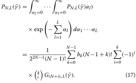
To derive the BER performance of theN × LMIMO RFID channel where N > 1, since the N receiving branches at the reader are not statistically independent as we mentioned earlier, we cannot use the above dis-tribution and its approximation to directly evaluate the performance of the MIMO channel by applying a widely used method as in [20,21] which assumes independency of receiving branches. Alternatively, we consider evaluating the BER using the conditional probability approach. We will see later, to analytically study the BER performance, we first need to investigate the properties of GN,L(·), a
function defined by a multi-variate integration. The func-tionGN,L(·)is defined as
GN,L(γ )¯¯ =
∞
αL=0
· · ·
∞
α1=0
1
1+ ¯¯γLl=1αl
N
×exp
− L
l=1 αl
dα1· · ·dαL. (10)
Hereαl is the squared magnitude of the channel gain of
the lth receiving branch, N andL are the index of the function GN,L(γ )¯¯ , and we define γ¯¯ = singγ2¯θ, where γ¯ is the average SNR and g is a constant which is mod-ulation dependent. For the coherent transmission case, the functionGN,L(γ )¯¯ is the moment generating function
(MGF) of the MIMO RFID channel withLtag antennas and N receiving antennas. For the non-coherent trans-mission case, the form ofGN,L(·)is required in deriving
the BER performance. The function GN,L(·) defined in
Equation (10) has the following recursive and asymptotic properties
Proposition 1.
G1,L(γ )¯¯ = e
1
¯¯ γ
¯¯
γ EL
1 ¯¯
γ
. =
⎧ ⎪ ⎪ ⎨ ⎪ ⎪ ⎩
ln(γ )¯¯ ¯¯
γ , ifL=1;
1
(L−1)γ¯¯, ifL>1.
Proposition 2. integers. The proofs of these propositions can be found in Appendix. With the above properties, we are now ready to derive the exact and asymptotic BER performances and study how the MIMO RFID backscattering channel behaves.
Non-coherent Case
We first investigate the non-coherent transmission case, which applies non-coherent equal gain combining (EGC) at the reader receiver side.
The channel gain at the nth receiving branch of the reader is given by hn = Ll=1h
f
lhbl,n. When fixing the
forward channel gainshfl’s, the channel gain hn is a
lin-ear combination of i.i.d. complex Gaussian random vari-ables, hence the conditional distribution ofhnonhfl’s is a
complex Gaussian distribution with varianceLl=1|hfl|2. Therefore, by fixing hfl’s, the N × L channel can be viewed as a single-input multiple-output (SIMO) channel in which each receiving branch is Rayleigh distributed and has power (or variance) Ll=1|hfl|2. Consequently using the result of the SIMO Rayleigh channel [23], we can have the conditional (onhfl’s) BER for theN×LRFID channel using non-coherent EGC as
PN,L(γ¯|hfl)=
which is modulation dependent [24]. Note that
The closed-form of the above exact BER can be com-puted recursively using Proposition 3 with the initial
knowledgeG1,L(γ )¯ = e
Table 1 shows a few examples under some antenna set-tings.
PN,L(γ )¯ =.
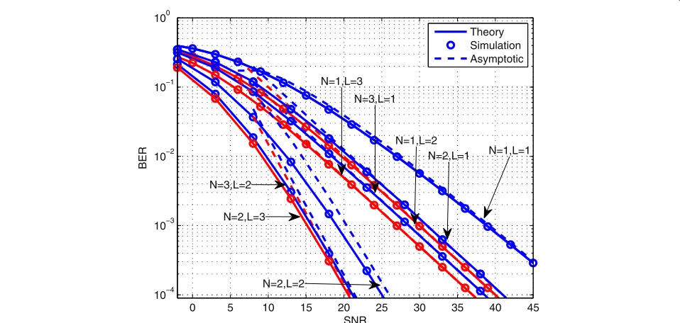
We can see that the above asymptotic BER form depends on the relation of the values ofLandN. Figure 3 shows the BER performances of theN×LRFID channels when employing the binary frequency-shift keying (FSK) with EGC.
The asymptotic diversity orderdacan be obtained as
da= lim
It means that the asymptotic diversity order of theN×L RFID channel under non-coherent transmission schemes is determined by the smaller value ofNandL. For the case ofL = N, compared with the case ofL = N, it requires a higher SNR to achieve the diversity orderN, because of the logarithm function in the numerator in Equation (18) whenN =L. This property means that even the diversity orders are the same the BER performances of the settings withN =L+1 orL=N+1 are remarkably better than the performance of the setting withN =L. The BER per-formance improvements fromN =L+1 toN = L+2, or fromL=N+1 toL=N+2, is not significant. These observations generalize the findings about the MISO case in [25].
Coherent case
We now look at the coherent detection case. We assume that the reader knows the channel state information (CSI) and MRC is applied at the reader receiver side.
Similar to our previous derivation, if we fix the forward gainshfl’s, the MIMO RFID channel can be viewed as a SIMO Rayleigh channel in which the receiving branches are independent and have power (or variance)Ll=1|hfl|2. Recall that the MGF for a Rayleigh fading channel is given
by1+ gγ¯ sin2θ
−1
[20]; therefore, the conditional MGF of theN×LRFID backscattering channel is
MN,L leads to the MGF for non-independent N receiving branches as
Using the moment generating approach in [20], the BER of theN×LRFID channel for the coherent case can be expressed as
Table 2 shows a few examples of the closed form of the MGF of the channel with coherent transmission scheme. Since the closed form ofGN,L(γ )¯¯ can be obtained
recur-sively using Propositions 1 to 4, the BERPN,L(γ )¯ can be
computed through the single integration in Equation (22) respective toθ. To have more insights on how the BER of theN×LRFID channel behaves, we also derive an asymp-totic form of this BER expression. Using Proposition 4, the asymptotic BER for Equation (22) can be expressed as
PN,L(γ )¯ =.
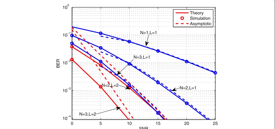
Figure 4 plots the BER curves of theN×LRFID channels when employing BPSK with MRC at the reader receiver antennas.
For theN×LRFID channel under the coherent case, the asymptotic diversity order can be given by
Table 1 Non-coherent case of the identical signaling scheme: closed-form BER expressions for theN×LRFID channel (Equation 17)
L=1 L=2
N=1 eg¯1γE1(
1
g¯γ)
2gγ¯ e
1
g¯γE2( 1
g¯γ)
2gγ¯
N=2 2e
1
g¯γE2(1
g¯γ)
gγ¯ +
2(−gγ¯+eg¯1γE1(1
g¯γ)+gγ )¯
gγ¯ +
(gγ )¯2−2gγ¯eg¯1γE1(1
gγ¯)+gγ¯−e
1
g¯γE1(1
g¯γ)
4(gγ )¯3
e 1
g¯γE1(1
g¯γ)−3(gγ )¯2+2(gγ )¯2e 1
g¯γE1(1
g¯γ)−gγ¯+4gγ¯e 1
g¯γE1(1
g¯γ)
4(gγ )¯3
As we can see that the asymptotic diversity order is still min(N,L) in the coherent transmission case, and the BER behavior is similar to that of the non-coherent case.
Performance analysis of MIMO RFID channel under OSTBC scheme
In this section, we analytically study BER performances and diversity gains of the N × L RFID channel when the orthogonal space-time coding scheme (OSTBC) is employed. OSTBC is one of the most attractive MIMO schemes with a very simple decoding process based on linear combining at the receiver. Because of its orthogo-nality, OSTBC achieves full diversityLN forL transmis-sion antennas andN receiving antennas in i.i.d. MIMO Rayleigh fading channels [26,27]. In this section, we inves-tigate the error rate performance of the MIMO RFID channel using the OSTBC scheme. For MIMO RFID sys-tems, OSTBC can be implemented by applying the sig-naling matrix in Equation (3) for the tag antennas. We assume that CSI is known by the reader and the channel is quasi-static.
Because of its orthogonality property, OSTBC can transform from the MIMO fading channel
r=Hs+w, (25)
to the following parallel SISO channels [28]
r=
||H||2 L s
+w, (26)
where
||H|| =
N
n=1
L
l=1
|hflhbl,n|2 (27)
is the Frobenius norm of H, s = (s1,. . .,sQ)T is the Q incoming symbols and the entries of w = (w1,. . .,wQ)T are i.i.d. Complex Gaussian random vari-ables with zero mean and unit variance. Similarly, the entries ofr=(r1,. . .,rQ)Tare the receiving symbols and can be detected based on a simple maximum likelihood method. The channel gain is divided by L because the transmission power should be normalized to unity. Since
0 5 10 15 20 25 30 35 40 45
10−4 10−3 10−2 10−1 100
SNR
BER
Theory Simulation Asymptotic
N=1,L=3
N=3,L=1
N=1,L=2
N=2,L=1 N=1,L=1
N=3,L=2
N=2,L=3
N=2,L=2
Table 2 Coherent case of the identical signaling scheme: MGFsGN,L(θ )for theN×LRFID channel (Equation 21)
L=1 L=2
N=1esin2g¯γθE1( sin2θ
g¯γ )
gγ¯
e sin2θ
g¯γ E2(sin2θ
g¯γ )sin2θ
gγ¯
N=2 e
sin2θ
g¯γ E2(sin2θ
g¯γ )sin2θ
gγ¯
− ¯γsin4θ+esin2θg¯γ E1(sin2θ
gγ¯ )sin6θ+ ¯γe
sin2θ
g¯γ E1(sin2θ
g¯γ )sin4θ (gγ )¯3
in real passive RFID signal transmissions, the transmis-sion energy is from the reader and is proportional to the number of tag antennas when the reader querying energy is fixed, we instead use the following model
r=||H||2s+w (28)
in which the transmission power is not normalized to unity. Let Eb denote the average energy per bit and Es
denote the average energy per symbol thenEs=Eblog2K whereKis the size of the signal constellation. The instan-taneous SNR per symbol is therefore given by
γ = ||H|| 2log
2K R
Eb N0 =
||H||2log2K
R γ¯= ||H|| 2gγ¯
(29)
whereRmeans the symbol rate and we defineg= log2K R .
Since evaluating the density of ||H||2 directly is dif-ficult, we consider the conditional probability approach as in previous derivations. Define |Hl|2 = n=N 1αlβl,n,
where αl = |hfl|2 andβl,n = |hbl,n|2. It is easy to check that |Hl|’s are i.i.d. random variables. Because ||H||2 =
L
l=1|Hl|2, for the SER analysis we can view theN×L
RFID channel which uses OSTBC as a virtual SIMO sys-tem withLreceiving branches in which MRC is applied at the receiver side. For thelth receiving branch of this SIMO system, the squared magnitude of the channel gain is|Hl|2 = Nn=1αlβl,n, whereαl is the channel power at
thelth receiving branch. We define the MGF of|Hl|2 as Gl(γ )¯¯ , whereγ¯¯ = singγ2¯θ, then the BER can be evaluated via
P(γ )¯ N,L= 1 π
π/2
θ=0
L
l=1
Gl(γ )¯¯ dθ. (30)
Now we need to derive Gl(γ )¯¯ . Since the conditional
channel gain|Hl|2 =Nn=1αlβl,ngivenαlcan be viewed
as the channel gain of another virtual SIMO system (i.e.,N Rayleigh distributed receiving branches with gainshbl,n’s, n=1,. . .,N) in which MRC is applied at the receiver side, consequently the MGF of|Hl|can be derived by averaging
the conditional MGFGl(γ¯¯|αl)overαl, withGl(γ¯¯|αl) =
1+αlγ¯¯
−N
being the MGF of anN-branches Rayleigh channel [20]
Gl(γ )¯¯ =
∞
αl=0
Gl(γ¯¯|αl)fαl(αl)dαl
=
∞
αl=0
1+αlγ¯¯−Nexp(−αl)dαl
= e 1
¯¯ γ
¯¯
γ EN
1 ¯¯
γ
. =
⎧ ⎨ ⎩
ln(γ )¯¯ ¯¯
γ , ifN=1;
1
(N−1)γ¯¯, ifN>1.
(31)
−5 0 5 10 15 20 25 30 35 40 45
10−4 10−3 10−2 10−1 100
SNR
BER
Theory Simulation Asymptotic
N=1 L=1 N=3,L=1
N=1,L=3
N=2,L=1 N=1,L=2
N=3,L=2 N=2,L=3
N=2,L=2
Substituting Gl(γ )¯¯ into Equation (30) yields the BER
expression of the N × L RFID channel for the OSTBC scheme
PN,L(γ )¯ =
1 π
π
2
θ=0
⎛ ⎝e
gγ¯
sin2θsin2θ
EN
sin2θ gγ¯
gγ¯ ⎞ ⎠
L dθ
(32)
. =
⎧ ⎪ ⎨ ⎪ ⎩
CL
ln(gγ¯)
gγ¯
L
ifN=1;
CL
1
(N−1)gγ¯
L
, ifN>1.
(33)
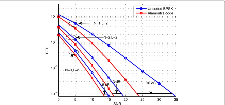
Figure 5 shows the SER/BER curves of Alamouti’s code with BPSK modulation in theN×LMIMO RFID channel (the SER and BER are exactly same for Alamouti’s code using BPSK).
Accordingly, for the N × L RFID channel with the OSTBC scheme, the asymptotic diversity order can be derived as
da= lim ¯ γ→∞
−logPN,L(γ )¯
log(γ )¯
=L. (34)
From Equation (34) we can see that here the achievable diversity order isL(the number of tag antennas), andN (the number of reader receiving antennas) does not affect the diversity gain. However, we note that there is a signif-icant BER improvement fromN = 1 toN > 1 due to
the logarithm function in Equation (33) whenN=1. This property is very different from that of traditional one-way channels in [27,29] and even very different from inde-pendent double Rayleigh channels [30], as we will see in comparisons in Table 3.
Results and discussions
In this section, we compare the error rate performances of the MIMO RFID backscattering channel with other forms of cascaded channels: the keyhole channel, the double scattering channel, and the independent double Rayleigh channel. We also compare the identical signal-ing scheme and the OSTBC scheme in the MIMO RFID channel and discuss how much improvement can be achieved by the OSTBC scheme under different antennas settings.
The pair-wise error probability for another cascaded channel which has independent receiving branches and the channel matrix of the following form
Hindep=
⎛ ⎜ ⎝
y1,1z1,1,y2,2z2,2, · · ·, yL,LzL,L
..
. . .. ...
yN,1zN,1,yN,2zN,2, · · ·, yN,LzN,L
⎞ ⎟
⎠ (35)
was discussed in [30] for space–time trellis code; how-ever, the performance of the identical signal scheme of this channel has not been studied yet. In this section, we give out its BER performance for comparison purposes. For
0 5 10 15 20 25 30
10−7 10−6 10−5 10−4 10−3 10−2 10−1 100
BER
SNR
Theory Simulation Asymptotic
3 dB 7 dB
N=3,L=2
N=2,L=2 N=1,L=2
Table 3 Diversity order comparisons between different cascaded structures
Channel and coding scheme Diversity order Performance bottleneck
RFID (identical) min(L,N) |L−N|>1
RFID (OSTBC) L N>2
Keyhole channel (OSTBC) min(L,N)[16] |L−N|>1
Double scattering channel (OSTBC) MLN/max(M,L,N)[18] −
Independent Double Rayleigh (identical) N L>2
Independent Double Rayleigh (OSTBC) NL[30] No bottleneck
non-coherent identical signaling transmission with EGC, the exact BER is given by
PN,L(γ )¯ =
whereU(a,b,x)is the confluent hypergeometric function, and the corresponding asymptotic BER expression
PN,L(γ )¯ =.
For coherent identical signaling transmission with MRC under perfect channel estimation, the exact and asymp-totic BERs are given by
PN,L(γ )¯ =
The derivations of the above results are given in Appendix.
Accordingly, we can show that the diversity order under both transmission schemes is
da= lim
Figure 6 and Figure 7 show the BER curve for the inde-pendent double Rayleigh channel with non-coherent and coherent transmission schemes, respectively. An interest-ing findinterest-ing is that, for the coherent transmission scheme, the result of the identical signaling scheme for the MIMO double Rayleigh channel with independent branches is similar to that of the MIMO RFID channel under the
OSTBC scheme, except the roles ofNandLare switched. The diversity order is given asNregardless ofL, but a sig-nificant BER performance improvement is observed from L=1 toL=2.
Diversity comparison and performance bottleneck
Under the identical signaling scheme, one interesting observation is that the diversity order of the stud-ied MIMO RFID channel is min(N,L), as shown in Equation (24). Equation (23) implies that if N− L > 1, solely increasing the number of receiving antennasNdoes not enhance the BER performance significantly. Similarly, ifL−N > 1, solely increasing the number of tag anten-nasLdoes not enhance the BER performance significantly either. Here, we refer to this observation as the perfor-mance bottleneck. In contrast, for both the Rayleigh chan-nel with independent receiving branches and the double Rayleigh channel with independent receiving branches, the diversity order isN, which means solely increasing the number of receiving antennas can significantly enhance the BER performance. Also there is a significant BER improvement fromL=1 toL=2 for the double Rayleigh channel with independent receiving branches, as shown in Equation (39). It is worth mentioning that, for the AF cooperative channel in Equation (17), the diversity order is(L+N)[17].
Under the OSTBC scheme, the diversity order of the studied MIMO RFID backscattering channel is the num-ber of tag antennas L, regardless of the number of the reader receiving antennas N, as shown in Equation (34). In contrast, for both the Rayleigh channel with indepen-dent receiving branches and the double Rayleigh channel with independent receiving branches, the diversity order is NL. The performance of the MIMO RFID channel is also significantly different from keyhole fading and double scattering fading. For the keyhole channel, the diversity order is min(N,L), and for the double scattering channel the diversity order isMLN/max(M,L,N).
0 5 10 15 20 25 30 10−4
10−3 10−2 10−1 100
SNR
BER
Theory Simulation Asymptotic
N=2,L=1 N=1,L=1
N=3,L=1
N=3,L=2 N=2,L=2
Figure 6BER performances (in Equations 36 and 37) of the MIMO independent double Rayleigh channel using non-coherent identical signaling (FSK with EGC).
N = 2 to N > 2, the BER improvement is not signif-icant, meaning that increasing the number of receiving antennas helps little whenN > 2. We consider this the performance bottleneck for the MIMO RFID backscatter-ing channel under the OSTBC scheme. While for both Rayleigh channel with independent receiving branches and double Rayleigh channel with independent receiving
branches, solely increasing the number of receiving or transmitting antennas can yield a higher diversity order and a significant BER performance improvement.
The above different behaviors of the MIMO RFID chan-nel are due to the special structure of the MIMO RFID backscattering channel. All the above discussions are summarized in Table 3.
0 5 10 15 20 25
10−4 10−3 10−2 10−1 100
SNR
BER
Theory Simulation Asymptotic
N=1,L=1
N=2,L=1 N=2,L=2
N=3,L=2
N=3,L=1
0 5 10 15 20 25 30 35 10−4
10−3 10−2 10−1
SNR
BER
Uncoded BPSK Alamouti’s code
N=2,L=2 N=1,L=2
1.5 dB 3 dB 10 dB N=3,L=2
Figure 8The BER performance comparison between Alamouti’s coding scheme and identical signaling scheme.A significant BER improvement by Alamouti’s code is observed forN=1, while the improvement is much smaller whenN≥2. These properties can be explained by our analysis of the MIMO RFID channel under the OSTBC and identical signaling schemes .
Performance improvement by employing OSTBC in RFID backscattering channel
In this section, we investigate how much performance enhancement can be brought by employing OSTBC in the studied MIMO RFID channel. Figure 8 compares the BER performances of Alamouti’s coding scheme and the iden-tical signaling scheme in theN×LRFID channel, where the RF tag is equipped with 2 antennas (i.e.,L = 2) and the number of reader receiving antennas varies from 1 to 3. A significant performance improvement (about 10 dB) is observed by Alamouti’s coding scheme for the setting N = 1. However, for the settings N = 2 andN = 3, the improvements by Alamouti’s scheme are not signifi-cant (i.e., 3 dB for N = 2 and 1.5 dB forN = 3). This observation can be explained by the derived asymptotic BER expressions in Equations (24) and (34): Our analysis for the OSTBC scheme implies that for Alamouti’s code the achievable diversity gain isL(L= 2 in this example) for anyNin theN ×LRFID channel. Consequently for the settings withN ≥ L, Alamouti’s code yields the same diversity order as that of the identical signaling scheme in the N ×L RFID channel, and the BER performance improvement is limited. In other words, when N ≥ L in a MIMO RFID system, OSTBC does not yield signif-icant performance improvement over simpler signaling schemes.
Conclusion
In this article, we analyzed the performance of the MIMO RFID backscattering channel, a cascaded channel that has
a special kind of structure. We observe several interesting properties of the channel from our analytical results. First, the diversity order is min(N,L)when employing the iden-tical signaling scheme and the diversity order isLfor the OSTBC signaling scheme. Second, the analytical results reveal that there is a performance bottleneck for the chan-nel. More specifically, with the identical signaling scheme, when |N −L| > 1 the BER performance enhancement is not significant by increasing the number of tag anten-nas or the number of receiving antenanten-nas alone. With the OSTBC signaling scheme, the SER performance enhance-ment is not significant whenN > L. These properties of the MIMO RFID channel are significantly different from that of other types of cascaded channels such as keyhole and double scattering. The analytical results and obser-vations presented in this article could provide a useful guidance for the design of RFID systems using multiple antennas.
Appendix
Proof of Proposition 1.LetA=1+ ¯¯γ Ll=2αl, then
∞
α1=0
exp(−α1) A+ ¯¯γ α1
dα1=
∞
α1=0
exp−α1−Aγ¯¯
¯¯
γ
α1+Aγ¯¯
e
A ¯¯ γd
α1+A
¯¯
γ
= e
A ¯¯ γ
¯¯
γ
∞
α1=A¯¯
γ
exp(−α1) α1 dα
1= e
A ¯¯ γ
¯¯
γ E1
A ¯¯
γ
.
whereα1 =α1+ γA¯¯ andE1(x)=
∞
t=xe−t/tdtare the
spe-cial functions called the exponential integral [22]. Now we have
The last step is obtained by the asymptotic property of the generalized exponential integralEL(·)[22].
Proof of Proposition 2.
∞ is just like that in Proposition 2.
Proof for Proposition 3.LetA=1+ ¯¯γLl=2αland
tN dt is the generalized exponen-tial integral. Using the relation thatEN(z) = N−11(e−z−
The last step is obtained by changing the index, i.e.,k = N−i.
Proof of Proposition 4.Case 1:N>L
sup-.
Therefore, Equation (14) is valid forN>L. Case 2:N=L
A similar approach as that of Case 1 can be obtained for this case; therefore, we omit the details here.
Proof for independent double Rayleigh. For the non-coherent transmission scheme, assuming that the instan-taneous SNRs forNindependent receiving branches are γ1,. . .,γN, its BER expression with respective to the instantaneous SNRs can be expressed as
PN,L(γt)= k}; therefore, we have
PN,L(γt)=
Averaging the densities of γn according to Equation
(8), we have the BER expression for the non-coherent transmission scheme as
PN,L(γ )¯ =
where evaluation of the integral can be found in [22] and U(a,b,x) is the confluent hypergeometric function. For small values ofx, the asymptotic expressions ofU(a,b,x) are given by [19]
U(a,b,x)=. −
Therefore, for large value ofγ¯, we can derive the follow-ing asymptotic BER expression
PN,L(γ )¯ =.
signaling MIMO setting ofLtransmitting antennas andN receiving antennas is expressed as
PN,L(γ )¯ =
The authors declare that they have no competing interests.
Acknowledgements
This study was supported by the Natural Sciences and Engineering Research Council of Canada (NSERC) under STPGP 364962-08.
Author details
1Department of Electrical and Computer Engineering, University of British
Columbia, Vancouver, Canada.2Department of Electrical Engineering, State University of New York (SUNY) at Buffalo, Buffalo, NY, USA.
Received: 25 August 2012 Accepted: 7 November 2012 Published: 29 November 2012
References
1. R Want, An introduction to RFID technology. IEEE Pervasive Comput.
13, 25–33 (2006)
2. F Klaus,RFID Handbook: Fundamentals and Applications in Contactless Smart Cards and Identification, 2nd edn. (Wiley, Hoboken, NJ, 2003) 3. P Nikitin, KVS Rao, inIEEE Antennas and Propagation Society International
Symposium. Performance limitations of passive UHF RFID systems, (9–14 July 2006), pp. 1011–1014
4. GD Vita, G Iannaccone, Design criteria for the RF section of UHF and microwave passive RFID transponders. IEEE Trans. Microw. Theory Tech.
53, 2978–2990 (2005)
5. D Yeager, F Zhang, A Zarrasvand, BP Otis, inISSCC 2010. A 9.2 uA gen 2 compatible UHF RFID sensing tag with -12 dBm sensitivity and 1.25 uVrms input-referred noise floor, San Francisco, USA, 7–11 Feb 2010), pp. 1011–1014
6. PV Nikitin, KS Rao, inIEEE International Symposium on Antennas and Propagation. Gain measurement of antennas using RFID, (3–8 July 2011), pp. 1012–1015
7. JD Griffin, GD Durgin, Multipath fading measurements for multi-antenna backscatter RFID at 5.8 GHz. IEEE Trans. Antennas Propagat.
58, 3693–3700 (2010)
8. D Kim, M Ingram, W Smith, Measurements of small-scale fading and path loss for long range RF tags. IEEE Trans. Antennas Propagat.51, 1740–1749 (2003)
9. JD Griffin, GD Durgin, Gains for RF tags using multiple antennas. IEEE Trans. Antennas Propagat.56, 563–570 (2008)
10. JD Griffin, GD Durgin, Gains For RF tags using multiple antennas. IEEE Commun. Lett.11, 735–737 (2007)
11. M Ingram, M Demirkol, D Kim, inInternational Symposium on Signals, Systems, and Electronics. Transmit diversity and spatial multiplexing for RF links using modulated backscatter, Tokyo, Japan, 24–27 Jul 2001), pp. 1–4 12. S Sarkka, M Huusko, VV Viikari, K Jaakkola, Phase-based UHF RFID tracking
with nonlinear Kalman filtering and smoothing. IEEE Sensors J.
12, 904–910 (2012)
13. JD Griffin, GD Durgin, Complete link budgets for backscatter radio and RFID systems. IEEE Antennas Propagat. Mag.51, 11–25 (2009)
14. B Strassner, K Chang, Passive 5.8-GHz radio-frequency identification tag for monitoring oil drill pipe. IEEE Trans. Microwave Theory Tech.
51, 356–363 (2003)
15. H Shin, JH Lee, Effect of keyholes on the symbol error rate of space-time block codes. IEEE Commun. Lett.7, 27–29 (2003)
16. Y Gong, KB Letaief, On the error probability of orthogonal
space-timeblock codes over keyhole MIMO channel. IEEE Trans. Wirel. Commun.6, 2402–2409 (2007)
17. M Elkashlan, PL Yeoh, RHY Louie, I Collings, On the exact and asymptotic SER of receive diversity with multiple amplify-and-forward relays. IEEE Trans. Veh. Technol.59, 4602–4608 (2011)
18. H Shin, MZ Win, MIMO diversity in the presence of double scattering. IEEE Trans. Inf. Theory.54, 2976–2996 (2008)
19. M Abramowitz, IA Stegun,Handbook of Mathematical Functions, 10th edn. (National Bureau of Standards, Washington, DC, 1972)
20. M Simon, M Alouini, A unified approach to the performance analysis of digital communication over generalized fading channels. Proc. IEEE.
86, 1860–1877 (1998)
21. DG Brennanr, Linear diversity combining techniques. Proc. IEEE.91, 331–356 (2003)
22. I Gradsheteyn, I Ryzhik,Table of Integrals, Series and Product, 7th edn. (Academic Press, New York, 1994)
23. J Proakis,Digital Communications, 4th edn. (McGraw-Hill, New York, 2001) 24. C Zhu, J Mietzner, R Schober, On the performance of non-coherent
transmission schemes with equal-gain combining in generalized K-fading. IEEE Trans. Wirel. Commun.9, 1337–1349 (2010)
25. C He, ZJ Wang, Closed-form BER analysis of non-coherent FSK in MISO double rayleigh fading/RFID channel. IEEE Commun. Lett.15, 848–850 (2011)
26. SM Alamouti, A simple transmit diversity technique for wireless communications. IEEE J. Sel. Areas Commun.16, 1451–1458 (1998) 27. V Tarokh, H Jafarkhani, A Calderbank, Space-time block coding for
wireless communications: performance results. IEEE J. Sel. Areas Commun.17, 451–460 (1999)
28. S Sandhu, A Paulraj, Space-time block codes: a capacity perspective. IEEE Commun. Lett.10, 384–386 (2000)
29. V Tarokh, N Seshadri, A Calderbank, Space-time codes for high data rate wireless communication: performance criterion and code construction. IEEE Trans. Inf. Theory.44, 744–765 (1998)
30. M Uysal, Diversity analysis of space-time coding in cascaded Rayleigh fading channels. IEEE Commun. Lett.10, 165–167 (2006)
doi:10.1186/1687-1499-2012-357
Cite this article as:Heet al.:On the performance of MIMO RFID backscat-tering channels.EURASIP Journal on Wireless Communications and Networking
20122012:357.
Submit your manuscript to a
journal and benefi t from:
7Convenient online submission
7Rigorous peer review
7Immediate publication on acceptance
7Open access: articles freely available online
7High visibility within the fi eld
7Retaining the copyright to your article