MIMO CONFIGURATION SCHEME WITH SPATIAL
MULTIPLEXING AND QPSK MODULATION
Yasir Bilal
1, Asif Tyagi
2, Javed Ashraf
3 1Research Scholar,
2Assistant Professor,
3Associate Professor,
Department of Electronics & Communication Engineering
,
Al-Falah School of Engineering and Technology, Faridabad, (India)
ABSTRACT
Multiple Input Multiple Output is an emerging technology that can greatly increase the capacity of a channel
without supplementary spectral resources. The only challenge is to get the output of transmitted signal with low
complexity and high performance and it can be achieved using optimal designing of detecting algorithm. In this
paper, Several MIMO Spatial Multiplexing detectors have been introduced and analyzed the result in terms of
bit error rate. There are several schemes that can be applied to MIMO such as Space Time Trellis Codes, Space
Time Block Codes,Vertical Bell Labs Space - Time architecture (VBLAST) and Spatial Multiplexing technique.
The main aim of this paper is to propose a signal detector scheme called MIMO detectors in order to increase
the MIMO channel performance. We investigate the MIMO system, spatial multiplexing scheme with Maximum
Likelihood (ML) Detection, Zero Forcing (ZF) Detection and Minimum Mean Square Error (MMSE) detection
and imitate this structure in Rayleigh Fading Channel.we also compare the performance of different MIMO
systems with QPSK Modulation in fading channels. Different characteristics and aspets have been discussed
and considered in this evaluation like signal to noise ratio (SNR), bit error rate (BER) and the number of
transmit and receive antennas. We compare the performances of SISO with MIMO and as well as compare the
performance among different MIMO sizes and graphs have been generated using MATLAB.It has been found
that ML receiver seems to have the optimum BER performance, Spatial Multiplexing achieves bit error rates
close to the ML scheme while retaining the low-complexity. Also we analyzed from the simulation that spatial
multiplexing performs in a similar way as Bell Labs Space – Time (BLAST) algorithm.
Keywords:
MIMO, Spatial Multiplexing, ML, MMSE and ZF.I. INTRODUCTION
It is well known that wireless communication networks can dramatically improve their throughput and
robustness by using MIMO at both the transmitter and receiver side in order to meet rapidly growing
requirement for broadband such as high quality audio and video. The existing wireless communication
technologies cannot support broadband data rates in an efficient way because of their sensitivity to fading.
MIMO wireless systems are motivated by two ultimate goals of wireless communication- viz high data rate and
Figure1: Diagram of MIMO Wireless Transmission System.
Transmitter and Receiver are Equipped with Multiple Antennas
There are three categories of MIMO techniques. The first one aims to enhance the reliability of a system by
decreasing fading effect through multiple spatial paths. Such techniques include STBC and STTC. The second
class aims to enhance the capacity by using layered approach. The example of this system suggested by Foschini
et al [3] is V- BLAST. Finally the third one probes the knowledge of the channel at transmitter. It decomposes
the channel coefficient matrix using SVD and uses these decomposed unitary matrices as pre- and post-filters at
the transmitter and the receiver to achieve near capacity [4]. Among them V-BLAST is mostly widely adopted
as it has low complexity and high spectral efficiency [5]. When maximum likelihood detector is utilised,
V-BLAST system experience receive diversity but the decoding complexity is ehhanced by the number of transmit
antennas. However, some near-ML schemes like Sphere-coding (SC) and semi -definite programming (SDP)
can be used to minimize the decoding complexity at low signal to noise ratio. When a large number of antennas
are introduced or high signal constellations are used, complexity of near -ML scheme might be still high. Some
suboptimal detectors have been elaborated, e.g., successive interference cancellations (SIC), decision feedback
equalizer (DFE), which are unable to collect receive diversity [6]. To further reduce the complexity, one can use
linear detectors like zero forcing, minimum mean square Error and maximum likelihood equalizers.
II. SPATIAL MULTIPLEXING
The Spatial Multiplexing can be understood by the concept of MIMO antenna configuration. In this process, we
divide the high data rate signal into multiple low data rate streams and each stream is transmitted from a
different transmitting antenna. These signals arrive at receiver antenna array with different spatial signatures.
The receiver then separates these streams into a parallel channel, thus improving the capacity. Thus we can say
that Spatial Multiplexing is a very strong technique for increasing channel capacity at higher SNR values.
The maximum number of spatial streams can be limited by the lesser number of antennas at the transmitter or
receiver side. Spatial multiplexing can be used with or without transmit channel knowledge
.
The cocept ofspatial multiplexing has been described in figure 2
III. CHANNELS
Channel can be defined as a transmission medium between transmitter and receiver. It can be wired or wireless.
In wired transmission we use some medium like coaxial cable, twisted pair cable or optical fiber and
transmission is smooth as compared with wireless transmission because received signal is not directly coming
from transmitter but the combination of reflected, diffracted, and scattered copies of the transmitted signal.
These signals are called multipath components. Rayleigh fading channel can be taken into consideration for the
analysis.
3.1 Rayleigh Fading Channel
Rayleigh Fading is an acceptable model if there are so many objects in the air that scatter the radio signal before
it arrives at the receiver. For sufficiently much scattered case, the central limit theorem expresses that the
channel impulse response will be well-modelled as a Gaussian process irrespective of the distribution of
individual components. If there will be no dominant component to the scatter, then such a process will have zero
mean and evenly distributed phase between 0 and 2π radians. The envelope of the channel response will
therefore be Rayleigh distributed. Calling this Random Variable R, the density function will have
P
R(r) = e
-r2/Ω, r ≥ 0
Where Ω = E (R2).
The gain and phase elements of channel’s distortion are often conveniently represented as a complex number.
Rayleigh fading is displayed by an assumption that the real and imaginary parts of the response are modeled by
independent and identically distributed zero-mean Gaussian processes so that the amplitude of the response is
the sum of two such processes.
IV. MODULATION TECHNIQUE
Modulation may be defined as the process of mapping the digital information into analog information in order to
transmit it over the channel. In Modulation, a binary signal changes binary bits into analog waveform.
Modulation can be done either by changing the amplitude, phase or frequency of sinusoidal carrier. Every
digital communication system has its unique modulator that is responsible for this task. There are several digital
modulation techniques used for data transmission.
4.1 Quadrature Phase Shift Keying
The most widely used modulation technique in Wireless Communication is QPSK that use four points in
constellation diagram equispaced around a circle. With four phases, QPSK can encode two bits per symbol as
Figure 3: QPSK Constellation Diagram
Quadrature phase shift keying is actually a form of PSK in which simultaneously two bits are modulatedby
selecting one of four possible carrier phase shifts (0, Π/2, Π, and 3Π/2). QPSK perform by changing the phase
of the In-phase (I) carrier from 0° to 180° and the Quadrature-phase (Q) carrier between 90° and 270°. This is
used to indicate the four states of a 2-bit binary code. Each state of these carriers is referred to as a Symbol. As
it has four states so it is a more bandwidth-efficient type of modulation than BPSK, possibly twice as efficient.
V. DETECTION SCHEMES
There are several detection schemes present with combination of linear and nonlinear detectors. The most
common techniques are ZF,MMSE and ML detection techniques. The generalized block diagram for MIMO
Detection techniques is shown in figure 4.
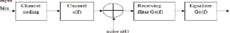
Figure 4: Block Diagram of System with Equalizer
5.1 Zero Forcing (ZF) Detection
Zero forcing refers to a form of linear equalization algorithm used in the communication system. It inverses the
frequency response of the received signal, this inverse is taken for the restoration of signal after the channel.
Robert lucky proposed the concept of zero forcing equalizer.The estimation of strongesttransmitted signal is
obtained by nulling out the weaker transmit signal. The strongest signal has been subtracted from received
signal and proceeds to decode strong signal from the remaining transmitted signal. ZF Detector ignores the
additive noise and may outstandingly amplify noise for the channel. It has many applications. For example it is
being studied for 802.11n (MIMO). The ZF equalizer is given by
W
ZF= (H
H)
-1H
HWhere
W
ZF is the equalization matrix and H is the channel matrix. Assuming MR ≥ MT and H has full rank,the result of ZF equalization before quantization is written
5.2 Minimum Mean Square Error (MMSE) Detection
Minimum mean square error equalizer minimizes the mean –square error between the output of the equalizer
and the transmitted symbol, which is a stochastic gradient algorithm with low complexity
.
The MMSEequalization is
W
MMSE= arg
GminE
x,n[║x- ẋ║
2]
Where WMMSE is equalization matrix, H channel correlated matrix and n is channel noise
Y
MMSE= H
H(HH
H+ n
oI
n)
-1y
5.3 Maximum Likelihood (ML) Detection
The idea is to assume a particular model with unknown parameters; we can then define the probability of
observing a given event conditional on a particular set of parameters. We have observed a set of outcomes in the
real world. It is then possible to choose a set of parameters which are most likely to have produced the observed
results.This is maximum likelihood. In most cases it is both consistent and efficient. It provides a standard to
compare other estimation techniques
.
Consider a sample (X1...Xn) which is drawn from a probability distribution P (X|A) where A are parameters. If
the Xs are independent with probability density function P (Xi|A) the joint probability of the whole set is
P(X
1…..X
n |A) = Π
ni=1P (X
i |A)
This may be maximised with respect to A to give the maximum likelihood estimates
.
VI. COMPARISON OF RESULTS
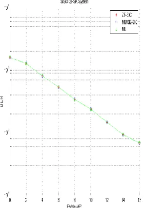
6.1 SISO with QPSK
If we analyse the performance of single input with single output antenna scheme with ZF, MMSE and ML, it is
crystal clear that all detectors perform in the same way therefore the resources of the receiver are completely
utilized or consumed by all the cast of high power and with high complexity. To better understand the cocept let
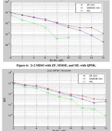
6.2 MIMO with QPSK
The improvement can be seen in the above result if we consider the 2x2, 3x3 and 4x4 MIMO scheme with
QPSK. Here MLSE performs better in comparison with the other considered approaches as shown in figure 6, 7
and 8.
Figure 6: 2×2 MISO with ZF, MMSE, and ML with QPSK.
Figure 8: 4×4 MIMO with ZF, MMSE and ML with QPSK
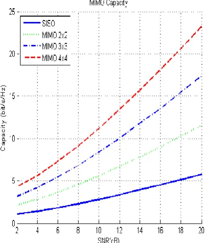
VII. DISCUSSION ON RESULTS
Let us look at the capacity of the multiple inputs and multiple output antennas considered in transmitters and
receivers. If we increase the size of MIMO like 2x2, 3x3, 4x4 etc. then the capacity of the MIMO is increased
with the size as shown in figure 9. No doubt that performance is also increased dramatically as we increase the
number MIMO size but when we see the simulation result, we find that capacity of 4×4 MIMO is high but at the
same time it needs a high simulation time and it has got more complexity, more power consumptions than 2×2
and 3×3 MIMO. Therefore we prefer such BER combination that has got less simulation time, less complexity
and less power consumptions. Based on this fact, we select the suitable combination to recover and equalizer our
VIII. CONCLUSION
We analyzed the performance of linear detectors for MIMO Spatial Multiplexing systems in Rayleigh fading
channel and AWGN channel for QPSK modulation, which exhibited the best trade-off between performance
and complexity among Spatial Multiplexing techniques. We show that conventional linear equalizers can only
collect diversity Nr-- Nt+1 for MIMO systems though they have very low complexity. By investigating and
simulating each receiver concepts, if Spatial Multiplexing implements a detection technique, i.e. MMSE
receiver and optimal ordering to improve the performance, although ML receiver appears to have the best BER
performance.
IX. FUTURE SCOPE
The MIMO principle is based on a Rayleigh multipath environment. So finally we proposed that ML detector
for MIMO-Spatial fading model with QPSK modulation is the ultimate optimization technique in the next
generation broadband communication system.
REFERENCES
[1] G. J. Foschini and M. J. Gans, “On limits of wireless communications i n fading environment when using
multiple antennas,”Wireless Personal Common. vol. 6, pp.311-335, Mar. 1998.
[2] V. Tarokh, N. Seshadri, and A. R. Calderbank, “Space-time codes for highdata rate wireless
Communication: Performance criterion and code construction,” IEEE Trans. Inf. Theory, vol. 44, no. 2, pp.
744–765, Mar. 1998
[3] P. W. Wolniansky, G. J. Foschini, G. D. Golden and R. A.Valenzuela, "V-BLAST: an architecture
forrealizing very high data rates over the rich- scattering wireless channel," In Proceeding of International
symposium onSignals, Systems Electronics, pp. 259-300, October 1998.
[4] J. Ha, A. N. Mody, J. H. Sung, J. Barry, S. Mclaughlin and G. L. Stuber, “LDPC coded OFDM with
Alamouti/SVD diversity technique,” IEEE Journal on Wireless Personal Communication, Vol. 23 ,Issue
1,pp. 183-194,Oct. 2002.
[5] G. D. Golden, G. J. Foschini, R. A.Valenzuela, and P. W. Wolniansky, “Detection algorithm and initial
laboratory results using V-BLAST spacetime communication architecture,” Electron. Let. vol. 35, no. 1,pp.
14-16, Jan. 7,1999.