Performance, diagnostics, controls and plans for the
gyrotron system on the DIII-D tokamak
J. Lohr1, M. Cengher1, J.L. Doane1, R.A.Ellis2, Y.A. Gorelov1, E. Kolemen2, C.P. Moeller1, S. Noraky1, B.G. Penaflor1, D.M. Ponce1, R. Prater1,M. Shapiro3 and D. Tax3
1General Atomics, San Diego, California 92186-5608, USA
2Princeton Plasma Physics Laboratory, Princeton, New Jersey 08540, USA 3Massachusetts Institute of Technology, Cambridge, Massachusetts 02139, USA
Abstract. The DIII-D ECH complex is being upgraded with three new depressed collector gyrotrons. The performance of the existing system has been very good. As more gyrotrons having higher power are added to the system, diagnostics of gyrotron operation, optimization of the performance and qualification of components for higher power become more important. A new FPGA-based gyrotron control system is being installed, additional capabilities for rapid real time variation of the rf injection angles by the DIII-D Plasma Control System are being tested and infrastructure enhancements are being completed. Longer term plans continue to include ECH as a major component in the DIII-D heating and current drive capabilities.
1 Present system, performance and plans
Gyrotron-based electron cyclotron heating and current drive systems have been in operation on the DIII-D tokamak for over 25 years [1]. At one time, 10 gyrotrons generating about 200 kW each at 60 GHz were operating, to study heating and current drive efficiency, to verify quantitatively the theory of wave-particle interactions at the fundamental of the electron cyclotron resonance frequency, and to study transport and creation of H-mode conditions [2]. Accessibility at higher density but above the cutoff frequency was enhanced when the 60 GHz system was replaced by a more powerful 110 GHz second harmonic system [3], eventually comprising six gyrotrons in the 1 MW class which, with the development of the CVD diamond output window, could reach pulse lengths on DIII-D in excess of 5 s at full power, while producing high quality Gaussian rf beams able to be injected directly into corrugated circular waveguide without phase correction. Although, during initial operation, the system experienced problems with gyrotron collector longevity and power supply design, the system now operates on a daily basis for experiments in many areas of fusion physics with very good reliability and stability in a variety of control modes. The complex routinely generates 4.7 MW and injects 3.5 MW, with 75% transmission efficiency from the gyrotrons to the tokamak at pulse lengths limited administratively to 5 s.
Despite continual modifications, expansions and upgrades, the reliability of the system has held constant at very close to 85% for the past 7 years, where, for example, the failure of a single gyrotron to run to the requested pulse length would give 83% reliability in the 6 gyrotron system for that shot. Because four of the gyrotrons at DIII-D are powered in parallel on two high voltage power supplies, an interlock trip for one of these paired tubes would necessarily take out two gyrotrons even though EPJ Web of Conferences
DOI: 10.1051/
C
Owned by the authors, published by EDP Sciences, 2012 ,
epjconf 201232/
020 (2012) 02
32 0 09
09
the paired tube did not fault. Therefore the individual gyrotron reliability is somewhat higher than stated for the overall average.
2010
2011
2012
2013
2014
2015
2016
0 5 10 15
12 8
4
0 P (MW)
P (MW)GEN
INJ
R.F. power Complete
Complete
In progress
Committed
Desired
Design 1.2 MW gyrotron
Build 1.2 MW (ARRA), design 1.5 MW
Operate 7 gyrotrons at 110 GHz, build 1.5 MW gyrotron at 117.5 GHz
Operate 7 gyrotrons at 110 GHz test/operate 117.5 GHz gyrotron
Install 2 more tubes, order n more, operate 8-10 gyrotrons
Replace 2 old 110 GHz gyrotrons with 1.5 MW 117.5 GHz tubes, opetrate 8-10 gyrotrons
Replace 4 old 110 GHz gyrotrons with 1.5 MW 117.5 GHz tubes, opetrate 8-10 gyrotrons
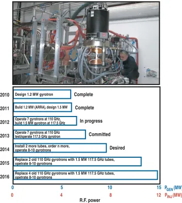
Fig. 1. In the DIII-D program trajectory, the ECH system is intended to comprise 10 gyrotrons by 2016, all with generated power in excess of 1.0 MW. Most of the gyrotrons will operate at 117.5 GHz. The photograph shows the 7th gyrotron, a 110 GHz depressed collector tube generating 1.2 MW for 10 sec pulses, during its recent installation.
All the gyrotrons in the present system are diode tubes [4] with conventional MIG guns and swept collector deposition. The newest three systems of this group are equipped with cryogen-free superconducting magnets [5], while two others have compressor cooled radiation shields with liquid helium cooled coils. The oldest magnet uses both liquid helium and liquid nitrogen, but has a helium reliquifier [6], which reduces the liquid helium consumption to less than 0.1% per day, requiring a refill at most once per year. This represents a cost effective alternative to a recovery system. Present plans call for installation of a second reliquifier and moving the remaining LHe cooled magnet to standby status as more cryogen-free magnets are acquired.
1 MW class diode gyrotrons, all of which operate at 110 GHz, will eventually be phased out and replaced by 117.5 GHz tubes designed to generate 1.5 MW at gyrotron thermal equilibrium, having operational pulse lengths of 10 s in the DIII-D application. In the first upgrade step, a 7th gyrotron, with a depressed collector, operating at 110 GHz and generating 1.2 MW, is installed and being commissioned during 2012, which will increase the total injected rf power to 4.4 MW. The next depressed collector upgrade tube has been designed to generate 1.8 MW for short pulses and 1.5 MW for operational pulse lengths up to 10 sec. at 117.5 GHz. This gyrotron should become operational during 2013. A second 110 GHz 1.2 MW depressed collector gyrotron has recently become available to the DIII-D program and is expected to be installed, possibly at the end of the 2012 DIII-D experimental campaign, to replace one of the older diode tubes. The tube replaced, in turn, will become a spare in an 8 gyroton system.
Depending on funding levels, the ultimate system on DIII-D will comprise, by approximately 2016, up to 10 gyrotrons, each generating between 1.2 and 1.5 MW, and operating primarily at 117.5 GHz. The current program plan is presented in Figure 1.
2 Modulation and real time steering of the RF beams
The Plasma Control System [8] on DIII-D provides real time control of the many parameters which affect the time dependence of the plasma shape, performance and position in the vacuum vessel. The PCS is now also being used to control the output power of the individual gyrotrons in the ECH system. Flexible modulation programs can be pre-loaded either locally at the ECH control console or at the PCS console to provide modulated heating with different waveforms at particular locations in the plasma for transport studies, or to study the effect of the rf beams on spatially localized instabilities. The PCS can control the duty cycle of the ECH output as a method of controlling the average output power without operating the gyrotrons at reduced intermediate output levels, which can increase the gyrotron collector loading. An input parameter for the ECH power feedback can be the local electron temperature, an MHD instability or an equilibrium parameter such as qmin. The
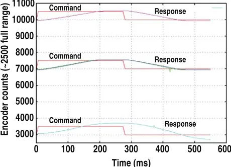
PCS is now being configured to be able to change the angles of the ECH launcher mirrors to steer the rf beams independently in the poloidal direction in response to pre-programmed commands or the need to mitigate plasma instabilities requiring real time command and response. Enhancements being added to the FPGA-based ECH control system include flexible control of the gyrotron filament power to compensate for cathode cooling during pulses and restart after faults, in which the gyrotron protection blocks the pulse prior to deposition of excessive energy in internal arcs, or the gyrotron experiences a change of operating mode, but it is desired to continue the rf pulse if possible.
RF
DIII-D ECH launcher Port edge
Infrared view of Gaussian R.F. beam exiting the launcher during tests of the port box limits
25 cm
Fig. 2. The power profile of the R.F. beam entering the tokamak is shown in infrared on a mylar target during mapping of the port box limits. The beam quality is excellent and it can be directed over the tokamak upper half plane with both co- and counter-current drive.
11000
Encoder count
s (
~
2500 f
u
ll rang
e)
10000
9000
8000
7000
6000
5000
4000
3000
Command Response
Response
Response
0 100 200 300
Time (ms)
400 500 600
Command
Command
Fig. 3. Real time steering of the launcher mirrors is being developed. The full 40º poloidal steering range is accomplished in 875 msec and all seven systems operate without mutual interference, having positioning accuracy of <1 cm at the tokamak center. Up and down tests of simultaneous motion of the mirrors are shown. Communications latency is 2.7 msec for read and 0.1 msec for write commands.
3 Launcher mirror upgrades
The rf beams are launched in the tokamak from the mouths of oversized circular corrugated waveguides 60 mm in diameter. Each beam strikes a weakly focusing fixed mirror, which reflects it through ~ 45° and directs it to the center of the flat steering mirror, which provides beam steering by tilting and rotating. Because of the relatively short rf pulses in DIII-D (<8 s), the mirrors are not actively cooled. Two of the launcher focus mirrors on the DIII-D system have experienced surface failures. Other mirrors have had incipient failures, indicated by localized fatigue cracking on the mirror surfaces, seen after long term service over several years. The focus mirrors were originally made from stainless steel with a 0.025 mm thick copper overcoat; and the steering mirrors were a brazed laminated design with a thin OFHC copper reflecting layer and stainless steel ribs to reduce eddy currents. Shutters, which were closed to protect the mirrors from deposits during discharge cleaning and baking, were found to be unnecessary and have been removed. The two failures in the focus mirrors were due to fatigue failure of the copper reflecting layers of the mirrors at the centers, where a stainless steel mounting stud restricted the heat transfer away from the reflecting surface. As a result of the thermal transfer problems, all the fixed focus mirrors have been replaced by solid Glidcop mirrors, which have the strength to withstand mechanical loads during disruptions and preserve excellent heat transfer properties. The movable steering mirrors, none of which have actually failed to date, were modified by insertion of additional copper near the center and replacement of the OFHC copper by CuCrZr alloy. Thermal modeling indicates that the maximum surface temperature for each type of mirror with the new designs will be <350ºC for 10 s pulses at 1.2 MW. The original mirrors and the design of the newly installed upgraded versions along with typical thermal model calculations are shown in Figure 4.
As a diagnostic to protect against mirror failures and arcing in the launchers, each dual launcher has a Langmuir probe, interlocked to the ECH pulse, at each waveguide mouth and a video record of the light in the launchers is continuously maintained using high definition cameras looking toward the plasma through windows in the launcher mounting flanges. Although rf sniffer probes have been investigated as a basis for interlocks in case of refraction, these did not provide sufficiently reliable protection, being prone to false alarms and providing slow response. Instead, we have developed algorithms based on kinetic profiles and equilibria, which remove the ECH pulse permit when it is likely that a cutoff layer will refract or completely reflect the rf beams.
Damaged copper overcoat on original focus mirror design
2 cm New solid Glidcop design
10 cm
Focus mirror
Steering mirror
T =320º C
SolidWorks max
More copper
New steering mirror 14 cm
4 Transmission efficiency
Increasing the efficiency of the waveguide transmission lines is a cost effective way to increase the injected R.F. power in the DIII-D ECH system. For the 31.75 mm diameter waveguides used in the DIII-D =3 mm system, the transmission line loss for the approximately 90 m waveguide runs with 10-12 miter bends, if the rf beam is entirely HE1,1, is -1 dB, or about 20% [9]. This ideal situation
can be achieved in low power tests with mode-filtered beams. Each miter bend, of which the DIII-D systems have approximately 10 per line, contributes about 1.5% mode conversion from the HE1,1
propagating mode per miter bend, or about -0.5 dB, some of which reaches the tokamak and some of which is lost as heating of the waveguides. In high power operation, small misalignments of the rf beam in tilt and offset at the point where the beam enters the waveguide result in mode conversion to other than the desired HE1,1 mode. The rf transmission efficiency, measured using calorimetry on the
heat loading for a high power dummy load located both at the gyrotron and then in the DIII-D machine area, averages 75% or 5% more than expected for perfect beams due to these effects.
Two changes were made to improve the transmission efficiency in the DIII-D installation: A reduction in the number of miter bends in each line; and an improvement in the alignment of the rf beams relative to the waveguides at the inputs. By eliminating the crossover gallery, a section of waveguides which gave flexibility in the connection of individual gyrotrons to specific launchers, 13 miter bends were eliminated from the entire system. The alignment at the waveguide inputs was improved [10] by careful adjustment of the MOU coupling mirror followed by infrared measurements of the rf propagating in the waveguides, launched into free space and then analyzed by a phase retrieval algorithm [11] to provide a measure of the mode quality in the waveguides. These steps increased the injected rf power by about 100 kW.
5 Conclusion
The gyrotron complex on DIII-D, currently comprising seven tubes in the 1 MW class, continues to be upgraded regularly and to perform well for plasma experiments, with excellent reliability. The system is becoming more flexible owing to enhancements in the controls and increased capabilities of the new gyrotrons while the injected power is increased.
This work was supported by the US Department of Energy under DE-FC02-04ER54698, DE-AC02-09CH11466, and DE-FC02-93ER54186.
References
1. R. Prater and C.C. Petty, Fusion Sci. Technol., 48, 1141 (2005) 2. J. Lohr, et al., Phys. Rev. Lett., 60, 2630 (1988)
3. J. Lohr, et al., Proc. 16th Joint Workshop on Electron Cyclotron Emission and Electron Cyclotron Resonance Heating (EC-16), R. Prater, ed., World Scientific, Singapore, 339 (2011) 4. K. Felch, et al., Proc. IEEE, 87, 752 (1999)
5. Cryomagnetics Inc., 1006 Alvin Weinberg Dr., Oak Ridge TN 37830 USA 6. Cryomech Inc., 113 Falso Dr., Syracuse, NY 13211 USA
7. Gregory S. Nusinovich, Introduction to the Physics of Gyrotrons, Johns Hopkins University Press, 230 (2004)
8. D.A. Humphreys, et al., Nucl. Fusion, 47, 943 (2007)
9. J.L. Doane and C.P. Moeller, Int J. Electronics, 77, 489 (1994)
10. Y.A. Gorelov, et al., Proc. Strong Microwaves: Sources and Applications, A.G. Litvak, ed., Russian Academy of Sciences, Nizhny Novgorod (2011)