255 |
P a g e
DESIGN AND MODELLING OF SENSORLESS VECTOR
CONTROLLED INDUCTION MOTOR USING MODEL
REFERENCE ADAPTIVE SYSTEMS
Janaki Pakalapati
1
Assistant Professor, Dept. of EEE,
Avanthi Institute of Engineering and Technology, Visakhapatnam (India)
ABSTRACT
In the present day scenario, much effort has been thrown in the area of electromechanical energy conversion,
especially towards the design of electromechanical conversion devices. Since recent years, the importance of
Induction Motors has been geared up due to the widest range of possible applications.
It is well known fact that electric energy consumption of the appliances can be reduced by controlling the speed of
the motor. The three phase variable speed IM drives are therefore encouraged to be used in the industry today as an
attractive solution forever increasing electricity generation cost. The methodology is undertaken according to these
stages: Study of the IM dynamic equations related Vector control, Construct the Vector control using Simulink
blocks, Implementation in field orientation control scheme.
In this thesis Vector control technique is used get high performance variable speed drive systems. Also attempt is
made to simulate the controller used to control the speed generated by the induction motor. The simulation studies
have been carried out for the vector control of induction motor with MRAS by using MATLAB/SIMULINK.
I INTRODUCTION
In 1882, Nikola Tesla identified the rotating magnetic field principle, and pioneered the use of a rotary field of force to operate machines. He exploited the principle to design a unique two-phase induction motor in 1883. An induction motor (IM) is a type of asynchronous AC motor where power is supplied to the rotating device by means of electromagnetic induction. Other commonly used name is squirrel cage motor due to the fact that the rotor bars with short circuit rings resemble a squirrel cage (hamster wheel).An electric motor convert‟s electrical power to mechanical power in its rotor.
256 |
P a g e
are widely used for single speed applications rather than variable speed applications due to the complexity of controlling algorithm and higher production cost of IM variable speed drives. However, there is a great interest on variable speed operation of IM within the research community mainly because IMs can be considered as a major industrial load of a power system. On the other hand the IMs consume a considerable amount of electricity generated. The majority of IMs are operated at constant speed, determined by the pole pair number and the stator supply frequency.
There are many senseless methods. Which, class to two kinds, open loop and closed loop. Up to this moment, there are many open loop sensorless schemes have been presented bur all of them have many defected by motor parameters like stator currents and stator voltage. But the closed loop method gets very low defected by motor parameters and feedback variable because calculate and estimate process always have feedback to adjust transition error. So, this closed loop control method is manage to estimate rotor speed by two models i.e one is reference model and another one is adaptive model, which is also used to estimate rotor flux and the error of 2 those signals have been adjusted through PI control unit. In this, the paper also concerning about stator resistance estimate method. It gives the result that estimate of rotor speed do not effect by stator resistance.
II RFOC CONTROL SCHEME
The class- field-orientated control (FOC) controls the d and q coordinate stator currents in separate. This control method is based on projections, which transform a three-phase time and speed dependent system into a two co-ordinate (d and q co-ordinates) time invariant system. These projections lead to a structure similar to that of a DC machine control. Field orientated controlled machines need two constants as input references: the torque component (aligned with the q co-ordinate) and the flux component (aligned with d co-ordinate). Asfield-orientated control is simply based on projections, the control structure can handle instantaneous electrical quantities; this makes the control accurate in every working operation (steady state and transient) and independent of the limited bandwidth mathematical model. The speed estimation technique based on MRAS was first proposed by Schauder. This is the best speed estimation techniques for both transient and steady state conditions of the speed response.
Decoupled flux and torque control of an induction machine can be realized by control of phase currents. If the stator voltage vector and stator current are defined in stationary common frame of reference as:
257 |
P a g e
Electromagnetic torque can be express in term of space vector as:
The torque equation change with the new reference frame:
From the rotor voltage equation on the new reference frame, we can get the rotor current as follow:
Substitute rotor current to rotor voltage equation, then we get
Separation into real and imaginary part, we have following equation:
258 |
P a g e
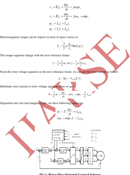
Consequently developed torque is proportional to slip frequency. If the stator d- axis current is held constant, torque can be instantaneously. The principal difference is however that in an induction machine both d-axis and q-axis stator current vector, while in a Dc machine excitation and armature current are completely independent as shown in fig 1. [1].
III SENSORLESS CLOSED LOOP
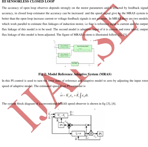
The accuracy of open loop observes depends strongly on the motor parameters and is effected by feedback signal accuracy, in closed loop estimator the accuracy can be increased and the speed signal give by the MRAS system is better than the open loop increase current or voltage feedback signals is not accurate. In MRAS there are two models which work parallel to estimate flux linkages of induction motor, i.e first is reference input is current and the output flux linkage of this model is to be used. The second model is adaptive, input of it is current and rotor speed, output flux linkage of this model is been adjusted. The figure of MRAS system is illustrated follow [2], [3].
Fig 2: Model Reference Adaptive System (MRAS)
In this PI control is used to turn the error state of reference and adaptive model to zero by adjusting the input rotor speed of adaptive model. The estimated speed from PI controller is
The system block diagram of a conventional MRAS speed observer is shown in fig [3], [4].
Fig 3: parallel rotor speed and stator resistance estimation
259 |
P a g e
The adaptive mechanism for speed
IV SIMULATION RESULTS
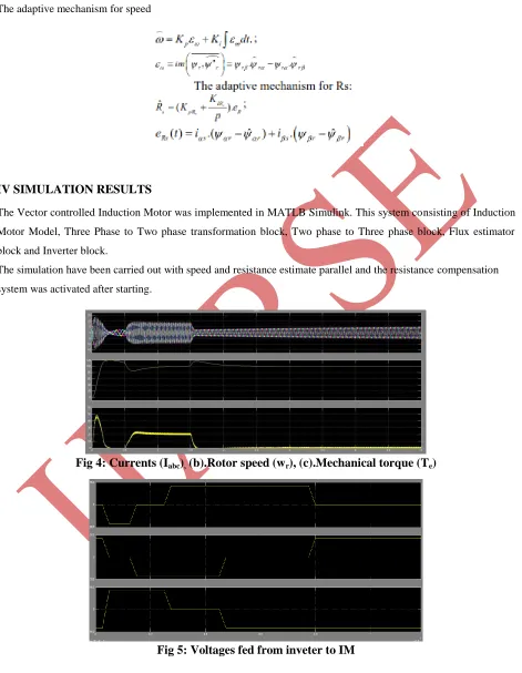
The Vector controlled Induction Motor was implemented in MATLB Simulink. This system consisting of Induction Motor Model, Three Phase to Two phase transformation block, Two phase to Three phase block, Flux estimator block and Inverter block.
The simulation have been carried out with speed and resistance estimate parallel and the resistance compensation system was activated after starting.
Fig 4: Currents (I
abc)
,(b).Rotor speed (w
r), (c).Mechanical torque (T
e)
260 |
P a g e
V CONCLUSION
In this thesis the principle of vector control of induction motor is given elaborately. The mathematical model of the drive system has been developed and based on mathematical modeling results have been simulated. Simulation results of Vector Control of induction motor were carried out by using Matlab/Simulink and from the analysis of the simulation results, the transient and steady state performance of the drive have been presented and analyzed.
From the simulation results, it can be observed that, in steady state there are ripples in torque wave and also the starting current is high. The main results obtained from the Simulation, the
Following observations are made.
i) The transient response of the drive is fast, i.e. we are attaining steady state very quickly. ii) The speed response is same as that of actual speed of induction motor in vector control.
REFERENCES
[1]R. Jotten and G. Maeder, “Control methods for good dynamic performance induction motor drives based on current and voltage as measured quantities,” IEEE Trans. Industry Applications, Vol.IA-19, no. 3, pp. 356-363, 1983.
[2] A. Abbondanti, and M. B. Brennen, “Variable speed induction motor drives use electronic slip calculator based on motor voltages and currents,” IEEE Trans. Industry Applications, vol. IA-11, no. 5, pp. 483-488, 1975
[3]Ehsan Hassankhan, and Davood A. Khaburi,” DTC-SVM Scheme for Induction Motors Fed with a Three-level Inverter.