IJEDR1502189
International Journal of Engineering Development and Research (www.ijedr.org)1091
Error Free Iterative Mitchell Algorithm Based
Multiplier for Image Filters
1Jeevana B, 2S Sridevi 1M.Tech,2Asst. Professor 1
Electronics and Communication
1CMRIT, Bangalore, Karnataka
________________________________________________________________________________________________________
Abstract - In digital image processing applications the quality of image depend on the Multipliers. Existing multipliers introduce errors in the output which will require more time, hence error free high speed multipliers has to be designed to overcome this problem. This paper presents a FPGA based iterative Mitchell Algorithm based multiplier for image filters by introducing error correction term in Karastuba-Ofman multiplier (KOM) architectures for image filters. The proposed multiplier is synthesized using Spartan 6 FPGA Family Device XC6SLX45-CSG324. Iterative Mitchell algorithm based multiplier improves the performance parameters such as area utilization, error, speed are better in the case of proposed architecture compared to existing architectures.
Index Terms - FPGA, Mitchell log multiplier, Karastuba-Ofman multiplier, PSNR.
________________________________________________________________________________________________________
I. INTRODUCTION
In many real-time DSP applications, speed is the main target and achieving this may be done at the expense of the accuracy of the arithmetic operations. Signal processing deals with signals distorted with the noise caused by amplifiers, quantization processes, non-ideal sensors, etc., as well as algorithms based on certain assumptions, results in inaccurate results. In many signal processing algorithms, which include correlation computations, here the exact value of the correlation is not much of important; only the maximum of the correlation is required. Multipliers will introduce small errors in the result which will not affect the result significantly and they are still acceptable in practice. Several researchers have found the use of Logarithmic Number System in divider /multiplier design. The two methods proposed in the literature are look up table (LUT), Mitchell Algorithm (MA). Interpolation based methods efficiently implement logarithmic operations but requires more hardware when compared to MA predicated calculation.
MA does not require a Look up table and shifting and counting operations are used for multiplication. Multipliers based on MA, the accuracy of the final result depends upon the procedure used to determine the log and antilog values. This is due to the simple piecewise approximation of the logarithm and antilogarithm curve. Many researches has been going on MA based multipliers, none of these researches had been succeeded to make zero error in MA. A novel approach has been introduced to reduce error rate of MA based multiplier, in fact zero error condition is also achieved with proposed algorithm.
II. RELATEDWORK
[1]In this paper to improve the accuracy of the Logarithmic multiplier Mitchell‟s based algorithms is used. Here the mantissa is divided into eight intervals and an average correction value is added in each intervals. To test multiplier Finite Impulse Response (FIR) Filter is used as part of a real application. This method offers an area saving of approximately 50% and for larger inp ut widths power saving is of 71%. This multiplier can additionally run at high speeds by pipelining the 3 main stages (error correction, logarithm calculation summation, antilogarithm calculation). [2] Proposed methods avoid logarithm approximation and introduce an iterative algorithm with various possibilities for minimizing the error and getting an exact result. Iterative method implemented four 16-bits multipliers, a multiplier with no correction terms, and three multipliers with two, three and four correction terms, respectively. The calculation of correction terms can be performed parallel in hardware. This iterative method reduces the error percentage of the MA by 44.7% by on the average. [3] Proposed an algorithm to efficiently compute radix-10 logarithm of a decimal number. In this algorithm 64-bit floating-point arithmetic is used, and is based on a digit-by-digit iterative computation. It does not require any correction or rounding circuitry hence it is suitable for critical applications which require timing and accuracy. The final logarithmic output is very accurate with a maximum absolute error of 3.53x . The architecture
is generalized and scalable. It can be extended for decimal 128 formats.
IJEDR1502189
International Journal of Engineering Development and Research (www.ijedr.org)1092
design Karatsuba algorithm is used. By combining classical and Karatsuba algorithm it is possible to obtain highly efficient multipliers. By applying Karatsuba algorithm squaring can be easily performed. The experimental results on FPGA‟s and other parameters such as delay, memory usage are compared between bit parallel Karatsuba Multiplier and Classical Multiplier. The comparison result says that Karatsuba multiplier is better than the other multipliers. The bit parallel Karatsuba multiplier consumes less resource among the known FPGA implementationMany researches has been going on MA based multipliers, none of these researches had been succeeded to make zero error in MA. A novel approach has been introduced to reduce error rate of MA multiplier, in fact zero error condition is also achieved with proposed algorithm.MA does not require a Look up table; shifting and counting operations are used for multiplication. Multipliers based on MA, procedure used to find the log and the antilog values impact the accuracy of the final result. This is due to the simple piecewise approximation of the logarithm and antilogarithm curve.
III. ERROR FREE 4X4MITCHELL LOG MULTIPLIER
The Proposed model is the combination of KOM and EFMLM. By using radix2 concept 16x16 multiplier to be implemented is decomposed into smaller order multiplier. Each 16x16 multiplier is decomposed into four 8x8 multipliers and each 8x8 multiplier is decomposed into sixteen 4x4 multipliers. In all 4x4 multiplication the EFMLM is used which results in zero error. In 4x4, 8x8 and 16x16 multiplications KOM is used along with 4x4 EFMLM to obtain zero errors.
Fig.1 Proposed 16x16 Multiplier
Fig.2 Error correction circuit
In the proposed error correction circuit 1st stage XOR gate output is sent as input to the second stage. 2nd stage XOR
gate output and is send as input to third stage. 3rd stage XOR gate output and is send as input to fourth stage.
Finally the output of all the four stage is added ( , , , ) to obtain error free result.
Algorithm (Iterative MA-based algorithm)[2]
.
IV. KOM in Proposed Model
KOM is an high speed, parallel multiplier architecture. The KOM product is given in Eq.1 .
(1) EFMLM’s 4x4 KOM 4x4 KOM 4x4 KOM 4x4 KOM 4x4 KOM 4x4 KOM 4x4 KOM 4x4 KOM 4x4 KOM 4x4 KOM 4x4 KOM 4x4 KOM 4x4 KOM 4x4 KOM 4x4 KOM 4x4 KOM 8x8 KOM 8x8 KOM 8x8 KOM 8x8 KOM 16x16 KOM KOM’s Adder Mitchell Block Mitchell Block Mitchell Block Mitchell Block
N1 N2
pp1
pp2 pp3
pp4 ni1 𝑛𝑖11 𝑛𝑖12 𝑛𝑖21 𝑛𝑖22 ni2
P(appro )
1. N1, N2: n-bits binary multiplicands. 2. Calculate k1: leading one position of N1
3. Calculate k2: leading one position of N2
4. Calculate (N1-2k1)2k2: shift (N1-2k1) to the left by k2 bits
5. Calculate (N2-2 k2
)2k1: shift (N2-2 k2
) to the left by k1 bits
6. Calculate k12 = k1 + k2
7. Calculate 2k1+k2: decode k12
8. Calculate P(0)approx: add 2k1+k2, (N1-2k1)2k2 and (N2-2k2)2k1
IJEDR1502189
International Journal of Engineering Development and Research (www.ijedr.org)1093
The KOM architecture used in implemented model is shown in fig 3. For multiplications the operands say a and b of size n bits are taken and an each n bit operand is decomposed into two n/2 bits operands. Operand a is decomposed into as and . Operand b is decomposed into and .Fig.3 KOM in Proposed Model [6]
The KOM performance is enhanced using pipelined architecture concept as shown in Fig.4. The architecture is organized into five stages viz., (1) Operand Decomposition stage (2) Adder 1st stage (3) Adder 2nd stage (4) Adder 3rd stage and (5) Operand Alignment stage and speed of multiplier is optimized with pipelining implementation. In pipelined KOM speed is double compared to non pipelined KOM.
Throughput Analysis of Pipelined KOM
To analyze throughput in pipelined architecture, for each operation one clock period is considered .In 1st clock period n bit operands are decomposed into four n/2 bit operands and are sent to n/2 KOM stage. During 2nd clock period, the first n/2 KOM outputs product, which is Partial Product say mid1( ) are sent to nth KOM stage. At 3rd period, second n/2 KOM outputs product, which will be mid2( ) are sent to nth stage. At 4th clock period, third n/2 KOM outputs product which is low( ) , simultaneously mid1 and mid2 are added in adder 1 of nth stage KOM. During 5th clock period, fourth n/2 KOM outputs high( ) , simultaneously low( ) is added with sum of mid1( ) and mid2( ) in adder 2 of nth KOM. At 6th clock period the product of fourth n/2 KOM high ( ) is added with sums of low ( ), mid1 ( ) and mid2 ( ) in adder 3 of nth KOM. During 7th clock period, the product is aligned. Generally seven periods are required to obtain product in the pipelined KOM. The KOM without pipeline requires nine clock periods such as one for operand decomposition, four for partial products generation, three for adders and one for product alignment. The number of clock periods required by pipelined KOM is less compared to KOM without pipelined hence the throughput is enhanced.
Fig.4 Pipelined Implementation of KOM [6]
n bit Full Adder
n bit Full Adder
PRODUCT (2n) Zero Extension
n/2 bit Barrel Shifter
n/2 KOM (aHbHZn) n/2 KOM (aHbLZn/2) n/2 KOM (aLbHZn/2) n/2 KOM (aLbL)
n bit Full Adder
n bit a(z) n bit b(z)
n/2 n/2 n/2 n/2
n
n n
n
n
n
n/2
n/2
n
IJEDR1502189
International Journal of Engineering Development and Research (www.ijedr.org)1094
Fig.5 Pipelined organization for throughput analysis in KOM [6]IV. APPLICATION OF PROPOSED MODEL TO NOISY IMAGE SMOOTHENING THROUGH GAUSSIAN FILTER
The Biometric is one of the important fields and it is used to identify person effectively since biometric traits cannot be shared. The several biometric traits such as Palm Print, Iris recognition, Finger Print, Signature, Voice recognition, Face recognition etc. are used to authenticate a person and the biometric samples may be corrupted with noise with high frequency components. Hence to eliminate high frequency components using filters pre processing is required. The noisy image is considered and Gaussian filter along with proposed multiplier is used to eliminate high frequency components. In Gaussian filters to eliminate high frequency components the noisy image is convolved with Gaussian kernel values and is sampled and truncated to obtain 3x3 Gaussian kernels as shown in Fig.6 for scaling 256.The 2-D, zero mean Gaussian function is given in Eq.2 .
(2)
=Standard deviation of the distributionFig.6 Gaussian 3x3 Kernel windows for
=1.0 with scaling factors 256.[6]The 3x3 matrix is considered from the noisy image. Noisy image is convolved with 3x3 Gaussian Kernel window using Eq.3.
(3)
For entire image convolution process is continued by shifting one column every time Where x = input noisy image,
h = filter mask, y =output image;
Height and width are respective height and width of image
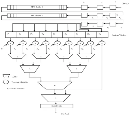
Hardware Implementation for Image filtering
Using Gaussian kernel the noisy image is filtered by adopting convolution. The architecture given below consists of two FIFO buffers in that FIFO buffer1 will read the first row of noisy image at every rising edge of clock. Each pixel value is send to FIFO buffer it s send to register window to constitute 3x3noisy image matrix. Register window is convolved with the Gaussian Kernel window of size 3x3 using proposed multiplier and Ripple Carry Adder. The register window of noisy image is shifted right by one column and convolved with Gaussian Kernel and this process is continued till the end column of image to complete process for first three rows of an image. The rows are shifted down by 1 to consider 2nd, 3rd and 4th rows for convolution process and are continued till end row of the noisy image to complete convolution process with whole noisy image.
1
256
48 2131
31 21
31
21 31
21
2 2 2
( )
2 2
1 ( , )
2
x y
G x y e
0 0
( , )
( , )
(
,
)
height width
i j
y m n
h i j
x m i n
j
IJEDR1502189
International Journal of Engineering Development and Research (www.ijedr.org)1095
Fig.7 Hardware Implementation for Image filteringAlgorithm of the Proposed Multiplier Inputs: a, b of size n is considered. Output: P of size 2n bits
Step1: aL=a[0 to (n/2-1)];Decompose a into 2 n/2 size operands, lower n/2 bits are aL and
Step2: aH=a[(n/2) to (n-1)] ; higher n/2 bits are aH.
Step3: bL=b[0 to (n/2-1)];Decompose b into 2 n/2 size operands, lower n/2 bits are bL and
Step4: bH=b[(n/2) to (n-1)] ; higher n/2 bits are bH
Step5: low= KOM (aLbL); operands sent to n/2th KOM stage to get low.
Step6: high=KOM (aHbH); Decomposed operands sent to n/2th KOM stage to get high
Step7: mid1=KOM (aHbL); Decomposed operands sent to n/2th KOM stage to get mid1
Step8: mid2=KOM (aLbH); Decomposed operands sent to n/2th KOM stage to get mid2
Step 9: The n/2th stage is decomposed into n/4,n/8….till 4x4, by repeating steps 1 to 8. Step 10: Calculate k1: leading one position of N1
Step 11: Calculate k2: leading one position of N2
Step 12: Calculate (N1-2k1)2k2: shift (N1-2k1) to the left by k2 bits
Step 13: Calculate (N2-2k2)2k1: shift (N2-2k2) to the left by k1 bits
Step 14:Calculate k12 = k1 + k2
Step 15: Calculate 2k1+k2: decode k12
Step 16:Calculate (1st stage of MLM): add 2k1+k2,(N1-2 k1
)2k2 and (N2-2 k2
)2k1
Step 17: Calculate ,(2nd stage of MLM). By repeating steps 10 to 16.1st stage XOR gate output is sent as input to second
stage.
Step 18: Calculate (3rd stage of MLM). By repeating steps 10 to 16.2st stage XOR gate output is sent as input to third stage Step 19: Calculate (4th stage of MLM). By repeating steps 10 to 16.3st stage XOR gate output is sent as input to fourth stage Step 20:Calculate PEFMLM by adding output of all the four stages of MLM. PEFMLM = + + + .The four PEFMLM „s of
4x4stage constitute Partial products for 8x8 stage.
Step 21: mid= mid1+mid2; mid1 and mid2 partial products added to get mid. Step 22: PKOM8x8=high+mid+low;Product of 8x8 stage is obtained.
Step 23: Products of 8x8 stage constitute Partial products of 16x16 stage.
Step 24: Steps 21 and 23 are repeated for higher stages of KOM, till n x n Multiplier stage.
V. RESULT
Proposed design is implemented using Hardware Description Language (VHDL). Multiplier designed is implemented on Spartan 6 family device, XC6SLX45-CSG324. The implemented multiplier is simulated using Modelsim 14.5.
Table 1 Area utilizations for 16 bit pipelined multipliers Multiplier (16x16) Slices 4 input LUT‟S IOB‟S
BB [2] 216 404 99
BB+1ECC [2] 427 803 99
BB+2ECC [2] 635 1189 99
BB+3ECC [2] 824 1546 99
Proposed 512 1344 65
Out Pixel 𝑟4 * 𝐾2 * 𝐾1 * 𝐾3 * 𝐾4 * 𝐾5 * 𝐾6 * 𝐾7 * 𝐾8 * 𝐾9 + + +
FIFO Buffer 1
FIFO Buffer 2
Data In 𝑟1 𝑟2 𝑟3 𝑟5 𝑟6
𝑟1 𝑟2 𝑟3 𝑟4 𝑟5 𝑟6 𝑟7 𝑟8 𝑟9
𝑟7 𝑟8 𝑟9 Register Window + + + + + Shift Divide
* Proposed Multiplier
IJEDR1502189
International Journal of Engineering Development and Research (www.ijedr.org)1096
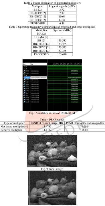
Table 2 Power dissipation of pipelined multipliersMultiplier Logic & signals (mW)
BB [2] 3.72
BB+1ECC [2] 7.32
BB+2ECC [2] 10.66
BB+3ECC [2] 13.37
PROPOSED 6.59
Table 3 Operating frequency comparisons of proposed and other multipliers Multiplier Pipelined(MHz)
MA [2] -
OD-MA [2] -
BB [2] 153.335
BB+1ECC [2] 153.335 BB+2ECC [2] 153.335 BB+3ECC [2] 153.335
PROPOSED 103.670
Fig.8 Simulation results of 16x16 KOM
Table 4 PSNR values
Type of multiplier PSNR of corrupt image(dB) PSNR of smoothened image(dB)
MA based multiplier[4] 14.4782 16.5914
Iterative multiplier 14.4782 18.88
Fig. 9 Input image
IJEDR1502189
International Journal of Engineering Development and Research (www.ijedr.org)1097
VI. CONCLUSIONFor each and every system design power dissipation, speed and silicon area are the three factors to be looked . These factors should in required levels, but optimization of all three factors at a time is not possible. Processors used in modern day systems /gadgets operate at GHZ speed; most of the applications have very high graphics contents in them. For such applications speed of DSP processor should be very high, while it should consume less power because most of devices will be portable and area of these devices should be less. In general DSP algorithms involve in intensive multiplications and additions. Hence speed of arithmetic components used in DSP processor should operate at high speed to keep track of non flickering graphical effects. A novel approach for logarithmic multiplier is implemented in project. The proposed error free Mitchelle log multiplier (EFMLM) satisfies all required conditions for modern design. EFMLM is synthesized using Xilinx ISE 14.5 on Spatran6 family device XC6SLX45-CSG324. The multiplier uses less area compared to existing logarithmic multipliers. The PSNR of the implemented multiplier is high when applied to noisy image to remove noise.
VII. REFERENCES
[1]D J McLaren, “Improved Mitchell-based Logarithmic Multiplier for low-power DSP applications,” Proceedings of IEEE International System On Chip Conference, pp. 53-56, September 2003
[2]Patricio Buli´c, Zdenka Babi´c and Aleksej Avramovi´c, “An Iterative Logarithmic Multiplier,” International Journal on Microprocessors and Microsystems, vol. 35, pp. 23-33, February 2011.
[3]Ramin Tajallipour, M d Islam and Khan A Wahid, “Fast Algorithm of A 64-bit Decimal Logarithmic Converter,” Journal of Computers, vol. 5, no. 12, pp. 1847–1855, December 2010.
[4]Deeksha R Shetty, Savitha Patil “Improving Accuracy in Mitchell‟s Logarithmic Multiplication Using Iterative Multiplier for Image Processing Application”International Journal of Soft Computing and Engineering (IJSCE) ISSN: 2231-2307, Volume-3, Issue-3, July 2013.
[5]Ajitha.S.S, Retheesh.D “Efficient Implementation OF BIT Parallel Finite Field Multipliers” IJRET ISSN: 2319-1163 Volume: 03 Issue: 03 Mar-2014.
[6]Satish S Bhairannawar1, Rathan R, Raja K B, Venugopal K R, L M Patnaik “FPGA Based Efficient Multiplier For Image Processing Applications Using Recursive Error Free MITCHELL Log Multiplier And KOM Architecture” International Journal of VLSI design & Communication Systems (VLSICS) Vol.5, No.3, June 2014
[7]Gang Zhou, Harald Michalik, and Laszlo Hinsenkamp.“ Complexity Analysis and Efficient Implementations of Bit Parallel Finite Field Multipliers Based on Karatsuba-Ofman Algorithm on FPGAs,” IEEE Transactions on Very Large Scale Integration (VLSI) Systems, vol. 18, no. 7, pp 1057-1066, July 2010.
[8]D. K. Kostopoulos, “An Algorithm for the Computation of Binary Logarithms,” IEEE Transactions. on Comp., vol. 40, no. 11, 0018-9340/91, November. 1991.
[9]Mark G. Arnold, Jesus Garcia and Michael J. Schulte, “The Interval Logarithmic Number System,” International Workshop on Power and Timing Modelling Optimization and Simulation,pp. 285–294, 2000.
[10]Bryson R. Payne, Saeid O. Belkasim, G. Scott Owen, Michael C. Weeks, and Ying Zhu, “Accelerated 2D Image Processing on GPUs,” ICCS 2005, LNCS 3515, pp. 256 – 264, 2005.
[11]Muhammad H. Rais, “Efficient Hardware Realization of Truncated Multipliers using FPGA,” World Academy of Science, Engineering and Technology, 2009.