ISSN(Online): 2319-8753 ISSN (Print): 2347-6710
I
nternational
J
ournal of
I
nnovative
R
esearch in
S
cience,
E
ngineering and
T
echnology
(A High Impact Factor, Monthly, Peer Reviewed Journal)
Visit: www.ijirset.com
Vol. 7, Issue 11, November 2018
GPRS Based Power Load Management
System
Lakshmi Narasimman.A1, Hamsadhwani. V2, Shanmugam. A1, Venitto.G1
UG Scholar, Department of EEE, Periyar Maniammai Institute of Science and Technology, Vallam, Thanjavur,
Tamil Nadu, India1
Assistant Professor, Department of EEE, Periyar Maniammai Institute of Science and Technology, Vallam, Thanjavur,
Tamil Nadu, India2
ABSTRACT: Load management is the process of balancing the supply of electricity on the grid with the electrical load by adjusting or controlling the load and to reduce the gap between the power demand and power generation. This balancing can be achieved by implementation of restriction and control, load shedding and by following energy conservation techniques. If this balance is not maintained, the stability of voltage and frequency would be affected. If the loads at the consumer end are made to tie up with Electricity Board (EB) mains as per prevailing voltage and frequency conditions, the grid disturbance and total blackout can be avoided and the system stability can be improved. If the quantum of connected load is curtailed based on the Time schedule and based on the sanctioned load, this load management can be effectively implemented. The techniques for proper power load management system with the use of PIC Microcontroller have been discussed. The PIC Microcontroller can measure the voltage, current, power and display the values and also actuate the relays by sending signals to the Driver circuit. The data measured by the PIC Microcontroller can also be communicated to the remote user by using GPRS technology.
KEYWORDS: Power Load management, Maximum Demand, Remote Monitoring, GPRS I. INTRODUCTION
The power demand in our country is getting increased day by day due to population growth, industrial development and technological development. To meet the growth in power demand, new generating plants have to be constructed with higher budget. The construction of new generating plants is time consuming and affects the major part of the country’s budget. Hence it is very essential to curtail the power demand within the power generation limits. It is called as power balancing which balances the power demand with power generation of the system. The above power balancing can be achieved by implementation of effective and proper power load management techniques. Direct control involves disconnection, reconnection and modification the operation of the consumer electrical devices by the Licensee. Indirect Control can be achieved by adopting different tariffs for different timings for encouraging the consumers to utilize the electrical power during off peak period rather than peak hours [1].
ISSN(Online): 2319-8753 ISSN (Print): 2347-6710
I
nternational
J
ournal of
I
nnovative
R
esearch in
S
cience,
E
ngineering and
T
echnology
(A High Impact Factor, Monthly, Peer Reviewed Journal)
Visit: www.ijirset.com
Vol. 7, Issue 11, November 2018
loads only and the Power loads should be isolated from EB mains or otherwise excess energy charges will be charged to the consumer [2].
The remote monitoring of supply voltage, current and power drawn from EB mains or from Generator is very useful to the Executives to gather information about the current status of the Industry to give appropriate instructions to their subordinates in their organization for effective load management and improve energy efficiency. General Packet Radio Service (GPRS) communication technology is used to develop inexpensive system for wireless electrical load monitoring from remote location continuously [3].
In the industry, the loads can be put into service according to the schedule for effective load management. The production is organized in such a way to avoid the high consumption loads such as induction furnace, welding sets during peak hours. Only low capacity electric loads are allowed to draw the EB supply during peak hours. Whenever the connected load exceeds the sanctioned demand, the low priority loads should be released from supply mains and load controller maintains the average demand and released load will be reconnected after a certain period when the total demand is within the sanctioned demand [4].
For proper power system operation, the voltage and frequency should be stable. The high voltage to the electrical equipment will weaken the insulation and reduce the life period and during under voltage the motors will not operate as per our requirement. The frequency of the system is directly proportional to the speed of the alternator and the speed is inversely proportional to the connected load. If loads are connected as per existing frequency conditions, the grid disturbance and total blackout can be avoided and the system stability can be improved [5].
The technologies and methodologies discussed above have been incorporated, integrated and implemented. The one way data transfer can be enhanced with two way communication for real time industrial applications.
II. DESCRIPTION OF THE SYSTEM
A. PIC Microcontroller
PIC microcontroller is the first RISC based microcontroller fabricated in CMOS (complementary metal oxide semiconductor) that uses separate bus for instruction and data allows simultaneous access of program and data memory. The main advantage of CMOS and RISC combination is low power consumption resulting in a very small chip size with a small pin count. The next advantage is that it has immunity to noise compared to other fabrication techniques. PIC Microcontroller has many special peripheral features such as memory with flash technology (data is retained even after the power is switched off), the program can be modified up to 10000times,10 bit multi-channel Analog to Digital Converter (converting analog data such as Voltage / Current into the digital form), Universal Synchronous Asynchronous Receiver Transmitter with 9 bit address detection (transmitting the data to remote location and for getting the data from the remote location), Synchronous serial port (interfacing output devices).These features makes it the right choice for the system.
EB Supply
Figure 1 Block Diagram of the system
B. Relay and Driver Circuit
ISSN(Online): 2319-8753 ISSN (Print): 2347-6710
I
nternational
J
ournal of
I
nnovative
R
esearch in
S
cience,
E
ngineering and
T
echnology
(A High Impact Factor, Monthly, Peer Reviewed Journal)
Visit: www.ijirset.com
Vol. 7, Issue 11, November 2018
C. Real Time Clock
Real Time Clock (RTC) using DS1307 is used along with PIC16F877A microcontroller to set the desired R&C Time as and when the consumer is directed by the Licensee to restrict the usage of electricity. The DS1307 Serial Real-Time Clock is a low-power; full binary-coded decimal (BCD) clock/calendar plus 56 bytes of NV SRAM for data storage. Address and data are transferred serially via a 2-wire, bi-directional bus. The clock/calendar provides seconds, minutes, hours, day, date, month and year information. The end of the month date is automatically adjusted for months with fewer than 31 days, including corrections for leap year. The clock operates in either the 24-hour or 12-hour format with AM / PM indicator. The DS1307 has a built-in power sense circuit that detects power failures and automatically switches to the battery supply.
D. Liquid Crystal Display
The Liquid crystal display used is Crystalonics dot–matrix (alphanumeric) liquid crystal displays. The use of C-MOS LCD controller and driver ICs result in low power consumption. These modules can be interfaced with a 4-bit or 8-bit microprocessor /Micro controller. It corresponds to high speed MPU interface. 80 x 8 bit display RAM, 9,920-bit character generator ROM for a total of 240 character fonts. 208 character fonts (5 x 8 dots) 32 character fonts (5 x 10 dots). 64 x 8 bit character generator RAM 8 character generator RAM 8 character fonts (5 x 8 dots) 4 characters fonts (5 x 10 dots)
E. SPDT Relay
The Single Pole Double Throw relays are used and the coil of a relay passes a relatively large current, typically 30mA for a 12V relay, but it can be as much as 100mA for relays designed to operate from lower voltages. Relays are usually SPDT or DPDT but they can have many more sets of switch contacts. A lever on the left is attracted by magnetism when the coil is switched on. This lever moves the switch contacts. There is one set of contacts (SPDT) in the foreground and another behind them, making the relay DPDT.
F. Power Supply
12Volts Battery is used as Voltage source and a separate charging unit fed by 230V AC supply is used for charging this Battery. The DC output voltage from the Battery is connected to the simple capacitor for filtering ripples if any and this is connected to the IC Voltage Regulator. This voltage regulator maintains the constant DC output even if the input dc voltage varies, or the load connected to the output dc voltage changes.
III. EXPERIMENTAL METHODS
A. MD Monitoring and Priority of Loads
ISSN(Online): 2319-8753 ISSN (Print): 2347-6710
I
nternational
J
ournal of
I
nnovative
R
esearch in
S
cience,
E
ngineering and
T
echnology
(A High Impact Factor, Monthly, Peer Reviewed Journal)
Visit: www.ijirset.com
Vol. 7, Issue 11, November 2018
Table 1 MD monitoring and Priority of Loads
B. Implementation of R and C on the
Required time
To check the function of Restriction & Control provisionof this system, the starting time for Restriction and Control was set as 18:00 Hrs and finishing time was set as 18:05 Hrs with the use of keypad for experimental purpose.
C. Frequency Monitoring and Load Management
The reference frequency range is set as 48-52 Hz for normal operating conditions in the PIC Microcontroller. The operation of PIC Microcontroller for the following frequency conditions were tested by varying the potentiometer.
D. Voltage Monitoring and Load Management
The reference voltage range is set as 200-245 Volts for normal operating conditions in the PIC Microcontroller. The operation of PIC Microcontroller for the following voltage conditions were tested by varying the potentiometer.
E. Remote Monitoring of Voltage, Current and Power
The data transfer of various parameters such as Voltage, Current and power of both EB circuit and Generator circuit between this system and remote Mobile Phone were checked by activating the GPRS module SIM and Android Mobile phone for various operating conditions.
IV. RESULTS AND DISCUSSION
1. Power measurement, MD monitoring and Priority of Loads
ISSN(Online): 2319-8753 ISSN (Print): 2347-6710
I
nternational
J
ournal of
I
nnovative
R
esearch in
S
cience,
E
ngineering and
T
echnology
(A High Impact Factor, Monthly, Peer Reviewed Journal)
Visit: www.ijirset.com
Vol. 7, Issue 11, November 2018
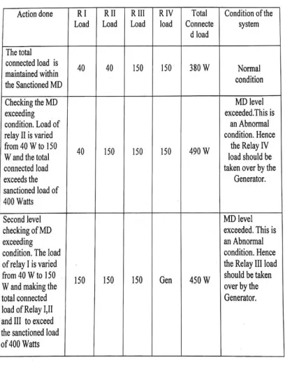
During the first level of MD exceeded condition, the PIC Microcontroller stopped the bias to the Driver Circuit of Relay IV and found least priority loads connected in Relay IV was transferred to Generator supply. During the second level of MD exceeded condition, the Microcontroller stopped the bias to the Driver Circuit of Relay III and next priority of loads connected in Relay III was transferred to Generator supply. During the above conditions, the LCD display interfaced with PIC Microcontroller displayed the value of the power in watts. Thus proper working of PIC Microcontroller and Relays were ensured and they fulfilled this Paper’s requirement of power measurement , MD monitoring and management of power load priority.
Table 2 Power measurement, MD monitoring and Priority of Loads
2. Implementation of R and C on the required time
The implementation of Restriction and Control was tested using this system and the test results are tabulated below.
Table 3 Implementation of R and C on the required time Load
Condition
Relay Loads fed by
Explanation
I II III IV
Normal
CL = 380 W EB EB EB EB
All the relays are in
energized condition.The
loads are fed by EB power through NO contacts of all relays.
MD exceeded First Level CL = 490 W
EB EB EB
EB to GE
N
The relay IV is switched
over to deenergized
condition and the load in Relay IV is fed by the Generator supply.
MD Exceeded
Second Level CL = 450 W
EB EB
EB to GEN
GEN
Already Relay IV load is fed by the Generator and now the relay III load is
changed over to
deenergized condition and the load in Relay III is fed by the Generator supply.
Condi tion
Tim e in Hrs
Relay Loads fed by
I II III IV
Before R&C
17:5 9
E
B EB EB EB
R&C Startin g Period 18:0 0 E B GE N GE N GE N R&C Finishi ng 18:0 5 E
ISSN(Online): 2319-8753 ISSN (Print): 2347-6710
I
nternational
J
ournal of
I
nnovative
R
esearch in
S
cience,
E
ngineering and
T
echnology
(A High Impact Factor, Monthly, Peer Reviewed Journal)
Visit: www.ijirset.com
Vol. 7, Issue 11, November 2018
At 18:00 Hrs, the loads connected across Relay II, III & IV were transferred to the Generator Circuit and load in Relay I (light load) remains in EB supply circuit. At 18:05 Hrs, the loads fed by the Generator circuit were reverted to the EB supply circuit. Thus proper working of PIC Microcontroller, RTC and Relays were ensured and this Paper’s requirement on Restriction and Control got fulfilled.
3. Frequency monitoring and Load management
The operation of PIC Microcontroller for the various frequency conditions was tested using this system and the test results are tabulated below.
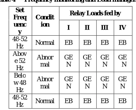
Table 4 Frequency monitoring and Load management
During under frequency (below 48 Hz) and over frequency (above 52 Hz) conditions, the PIC Microcontroller stopped the Bias to the Driver Circuits pertaining to Relay I,II,III and IV .All the loads were transferred from EB supply circuit to the Generator Circuit. When frequency returns to normal level, all the loads were fed by the EB supply circuit. Thus proper working of PIC Microcontroller and Relays were ensured and this Paper’s requirement on Frequency monitoring got fulfilled which would protect the sensitive equipments connected in the system and the stability of grid could be maintained during abnormal frequency conditions.
4. Voltage monitoring and Load management
The operation of PIC Microcontroller for the various voltage conditions was tested using this system and the test results are tabulated below.
During under voltage (below 200V) and over voltage (above 245V) conditions, the PIC Microcontroller stopped the Bias to the Driver Circuits pertaining to Relay I, II, III and IV. All the loads were transferred from EB supply circuitto the Generator Circuit. When voltage returns to normal level, all the loads were fed by the EB supply circuit. Thus proper working of PIC Microcontroller and Relays were ensured and
Set Freq uenc y
Condit ion
Relay Loads fed by
I II III IV
48-52
Hz Normal EB EB EB EB Abov
e 52 Hz
Abnor mal
GE N
GE N
GE N
GE N
Belo w 48
Hz
Abnor mal
GE N
GE N
GE N
GE N
48-52
ISSN(Online): 2319-8753 ISSN (Print): 2347-6710
I
nternational
J
ournal of
I
nnovative
R
esearch in
S
cience,
E
ngineering and
T
echnology
(A High Impact Factor, Monthly, Peer Reviewed Journal)
Visit: www.ijirset.com
Vol. 7, Issue 11, November 2018
Table 5 Voltage monitoring and Load management
and this Paper’s requirement on Voltage monitoring were fulfilled which would protect all the equipments connected in the system from abnormal voltage conditions.
5. Remote monitoring of Voltage, Current and power
The data transfer between this system and remote Mobile Phone were checked for various operating conditions and the display results for various conditions are tabulated below.
N - refers Normal condition ; A - refers Abnormal condition
Table 6 Remote monitoring of Voltage, Current and power Set
Volta ge
Con ditio n
Relay Loads fed by
I II III IV 200
to 245 V
Nor
mal EB EB EB EB
Abov e 245
V
Abn orma
l
GE N
GE N
GE N
GE N
Belo w 200
V
Abn orma
l
GE N
GE N
GE N
GE N
200 to 245 V
Nor
ISSN(Online): 2319-8753 ISSN (Print): 2347-6710
I
nternational
J
ournal of
I
nnovative
R
esearch in
S
cience,
E
ngineering and
T
echnology
(A High Impact Factor, Monthly, Peer Reviewed Journal)
Visit: www.ijirset.com
Vol. 7, Issue 11, November 2018
From the above results, it is evident that the GPRS module in the system was satisfactorily interlinked with the remote Mobile phone and the parameters displayed in the Mobile phone were accurate and similar to the values in LCD. Thus proper working of PIC Microcontroller and GPRS module of this paper were ensured and this Paper’s requirement on continuous remote monitoring of various electrical parameters and status of power loads using GPRS technology got fulfilled.
V. CONCLUSION
Load management in both Industrial and commercial sector has gained its significance recently. For proper load management the implementation of R&C measures and monitoring power, Voltage and frequency are very essential. In this paper, a low cost integrated power load management along with GPRS communication has been designed and explained. The system was subjected to various electrical environments and the functions of the system were checked and the results are well within the expected values and satisfactory. If the system is modified according to Industrial environment, there will be no doubt that this would be the best and inexpensive system in the prevailing market.
REFERENCES
[1] Montaser Attakassem, Abdelfatah Ali Elahwil, “Power Load Management -Techniques and Methods in Electric Power System” in International Research Journal of Engineering and Technology (IRJET) Dec 2015.
[2] TNERC, “Tamilnadu Electricity Supply Code” Jan-2010.
[3] Mladen Knezic, Zeljko Ivanovic, and Branko Dokic, “GPRS-Based Electrical Energy Monitoring System”, in IX Symposium Industrial Electronics (INDEL) Nov-2012.
[4] W. Grattieri, A.Demouselle, T.Dunne , H.R. Hagmann, J.M.H. Kevers, S. Lindskoug, H.Ottosson, J.F.Reynaud,H. Aoki, “Electric Load Management in Industry”, in www.leonardo energy.org Jan-2009.