ABSTRACT
PATSILARAS, GEORGE. Leveraging Coupled Cores for Single-Threaded Application Performance. (Under the direction of Dr. James Tuck.)
The shift to multicores has resulted in a focus on parallel applications. At the same time, not all applications can benefit from parallelization techniques for two reasons. The first reason is the increased complexity of the hardware, which makes it difficult for the programmer to optimize for performance due to variable communication latency between cores. The second reason is due to not all applications having code which can be parallelized. For these applications the focus has been to reduce the long memory latencies.
At the same time, the projected amount of dark silicon (the fraction of the chip powered off) on a chip is growing. Hence, Asymmetric Multicore Processors (AMP) offer a unique op-portunity to integrate many types of cores, each powered at different times, in order to optimize for different regions of execution. We design an AMP with both a core specialized for Memory Level Parallelism (MLP) and one specialized for Instruction Level Parallelism (ILP). We pro-pose a hardware-level, application steering mechanism called Symbiotic Core Execution (SCE). SCE detects MLP phases by monitoring the L2 miss rate of the application, and it uses that information to steer the application to the best core. Interestingly, we show that L2 miss rates are important for deciding when an MLP region begins and when it ends. As a program runs, its execution migrates to a core customized for MLP during regions of high MLP; when the region ends, it is re-scheduled on the core that fits the application characteristics. This way we can utilize the shift to multicores and improve single-threaded applications.
in such a way that their meaning is hard to glean from the hardware at run time. Hence, there is a wide gap between the programmers understanding and the resulting behavior at run time. In order to give programmers higher performance, hardware can be designed to better match the programmers abstraction.
© Copyright 2012 by George Patsilaras
Leveraging Coupled Cores for Single-Threaded Application Performance
by
George Patsilaras
A dissertation submitted to the Graduate Faculty of North Carolina State University
in partial fulfillment of the requirements for the Degree of
Doctor of Philosophy
Computer Engineering
Raleigh, North Carolina
2012
APPROVED BY:
Dr. Gregory Byrd Dr. Vincent Freeh
Dr. Eric Rotenberg Dr. James Tuck
DEDICATION
BIOGRAPHY
ACKNOWLEDGEMENTS
As my ten-ure as a student, correction eleven-year, journey at North Carolina State University comes to an end, I would like to thank many people for their help in getting by the happy an difficult moments.
I would like to thank my advisor for his help and patients to all my crazy ideas. I am also appreciative of my PhD committee members, Dr. Byrd, Dr. Rotenberg, and Dr. Freeh for their valuable feedback and guidance. Dr. Viniotis for his graduate school advise.
I would like to thank my father, mother and sister for the tremendous support and reminding me to believe in myself and keep on working hard.
My soon to be wife, Teri, for her support and patience.
TABLE OF CONTENTS
List of Tables . . . vii
List of Figures . . . .viii
Chapter 1 Introduction . . . 1
1.1 Efficiently Exploiting Memory Level Parallelism on Asymmetric Coupled Cores for Single-Threaded Performance . . . 2
1.2 Improving Fine-Grain Thread Level Parallelism Using Abstract Queue Operations 5 1.3 Published Work . . . 8
1.4 Organization of Document . . . 8
Chapter 2 Efficiently Exploiting Memory Level Parallelism on Asymmetric Coupled Cores for Single Threaded Performance . . . 9
2.1 Background . . . 10
2.1.1 Application Limitations for High Performance . . . 10
2.1.2 Effects of a Core’s Width on Cycle Time . . . 11
2.1.3 Checkpointed L2 Miss Processing with Value Prediction:CLP+VP . . . . 12
2.1.4 Complexity . . . 13
2.1.5 Core Customization . . . 14
2.2 Motivation . . . 15
2.2.1 Effects of MLP Techniques on Different Cores . . . 15
2.2.2 Exploring MLP on Different Core Widths . . . 16
2.3 Symbiotic Core Execution . . . 19
2.3.1 Overall Architecture . . . 20
2.3.2 SCE Mode Scheduling . . . 21
2.3.3 Preferred Core Scheduling . . . 22
2.3.4 MLP Region Detection . . . 23
2.3.5 MLP Epoch Scheduling . . . 26
2.4 Evaluation of SCE . . . 26
2.4.1 Experimental Setup . . . 26
2.4.2 Power Modeling . . . 28
2.4.3 Performance Compared to Symmetric Multicore Processors . . . 30
2.4.4 Power and Energy Delay2 . . . 31
2.4.5 Performance Compared to Asymmetric Multicore Processors . . . 32
2.4.6 SCE Execution Analysis . . . 34
2.4.7 Sensitivity to Scheduling Parameters . . . 37
2.4.8 MLP Region Scheduling Benefits onCLP+VP . . . 38
2.5 Related Work . . . 39
2.5.1 Memory Level Parallelism . . . 39
2.5.2 Asymmetric Multicore Processors . . . 40
Chapter 3 Improving Fine-Grain Thread Level Parallelism Using Abstract
Queue Operations on Multicores . . . 42
3.1 Bridging the Multicore Abstraction Gap . . . 42
3.1.1 Properties of Abstract Parallel Operations . . . 42
3.1.2 An Architectural Design Pattern for Abstract Parallel Operations . . . . 44
3.1.3 Examples . . . 46
3.2 Architecting a Single-Producer/Single-Consumer Queue as an Abstract Parallel Operation . . . 47
3.2.1 Overview of Architecture . . . 47
3.2.2 Queue Data Structure and DS$ for Enqueue/Dequeue Operations . . . . 50
3.2.3 Resource Arbitration . . . 53
3.2.4 Performance Optimizations . . . 54
3.2.5 Miscellany . . . 57
3.3 Evaluation . . . 59
3.3.1 Micro-Benchmark . . . 60
3.3.2 Decoupled Software Pipelining . . . 62
3.4 Related Work . . . 65
3.5 Discussion and Summary . . . 66
Chapter 4 Conclusion . . . 68
LIST OF TABLES
Table 2.1 Asymmetric Core Configurations . . . 16
Table 2.2 Core Details. Cycle counts are in processor cycles . . . 27
Table 2.3 Core Configurations . . . 28
Table 2.4 Characterizing SCE: Total overhead of switching over entire execution, scheduling accuracy and value predictor accuracy . . . 35
Table 2.5 Characterizing Execution in SCE Mode: Percent of execution spent on Core4and Core2+CLP+VP in SCE mode . . . 36
Table 3.1 Applying Architectural Design Pattern to Abstract Operations. . . 46
Table 3.2 AQO Actions on Specific Coherence Actions . . . 52
Table 3.3 Architecture simulated. . . 59
Table 3.4 System configurations with various queues. . . 60
LIST OF FIGURES
Figure 1.1 Multicore Abstraction Gap. . . 6
Figure 2.1 Function price out impl( network t *net) in mcf . . . 10
Figure 2.2 Scaling of Issue Queue in terms of delay . . . 11
Figure 2.3 MLP regions . . . 13
Figure 2.4 Virtual instruction window of CLP+VP . . . 15
Figure 2.5 Performance of different core widths normalized to Core4 . . . 17
Figure 2.6 Performance versus MLP potential . . . 18
Figure 2.7 Percent of Total Execution Spent in Different L2 Bins . . . 19
Figure 2.8 Architecture of Tile and AMP . . . 20
Figure 2.9 SCE scheduling algorithm . . . 23
Figure 2.10 Responsive Switching to MLP Core . . . 24
Figure 2.11 Lazy Switching to Preferred Core . . . 25
Figure 2.12 SCE scheduling for MLP being the preferred core . . . 26
Figure 2.13 Power breakdown of each component in a multicore . . . 30
Figure 2.14 Speedup for SCE CLP+VP, Core2, Core2 CLP+VP, and Core4 CLP+VP normalized to Core4 . . . 31
Figure 2.15 Power for SCE CLP+VP, Core2, Core2 CLP+VP, and Core4 CLP+VP normalized to Core4 . . . 32
Figure 2.16 Energy Delay2 for SCE CLP+VP, Core2, Core2 CLP+VP, and Core4 CLP+VP normalized to Core4 . . . 33
Figure 2.17 Speedup for SCE all, SCE none, SCE4, and SCE imm normalized toSCE none . . . 34
Figure 2.18 Sensitivity to scheduling parameters. . . 37
Figure 2.19 Increase in executed instructions fromCLP+VPvs benefit of MLP region scheduling . . . 38
Figure 3.1 Scaling of Issue Queue in terms of delay . . . 43
Figure 3.2 APO Design Pattern. . . 44
Figure 3.3 Architectural Overview and Semantics for Hardware Queue. . . 47
Figure 3.4 Queue Data Structure and Operations. . . 50
Figure 3.5 Coordinating actions with the hardware queue using Red Zone Dequeueing. 55 Figure 3.6 Performance of AQOwith Unidirectional Micro-Benchmark. . . 61
Figure 3.7 Speedup of AQOusing DSWP over HAQu. . . 62
Figure 3.8 Normalized L2 Cache accesses. . . 63
Figure 3.9 Normalized Energy consumption. . . 63
Chapter 1
Introduction
The last two decades of single thread performance scaling have been a golden era for computer architecture. In this period, programmers focused on implementing correct programs using high level languages and relied heavily on advances at the architectural level and below to transparently speedup their code from one processor generation to the next. As frequency scaling has slowed down due to power constraints, so has the increase in single-threaded performance. Until now, clock frequency performance was predominantly increased linearly depending on the memory footprint of applications.
Chip Multicore Processors (CMPs) have superseded large monolithic processors due to the latter’s excessive design complexity and high power consumption. As a result, most CMP designs have focused on increasing the number of cores and on re-organizing the memory hierarchy. This reflects a bias toward parallel and multi-programmed workloads, and deemphasizes single-threaded performance concerns.
them concurrently. The more threads that overlap, the larger the performance gains. However, not all single-threaded applications can be parallelized. For those applications that cannot be parallelized, specialized, asymmetric multicore processors (AMPs) can improve performance by executing different regions of code on the best suited cores.
DSWP attempts to exploit fine-grain parallelism. At the same time, performance challenges remain, primarily due to communication between cores being hampered by 10s of cycles of delay through the interconnect and cache coherence protocol. This problem increases as we add levels of cache to the cache hierarchy, despite processors being located side-by-side within a few clock cycles (of wire delay).
AMPs have been shown to improve power efficiency for single-threaded applications. How-ever, performance improvements remain challenging, primarily due to two runtime decisions. The first decision is the need of AMPs to know which core is best for a certain region. The second decision is the need to know how to identify different phases to execute on the available cores.
This dissertation presents two hardware optimizations to improve performance and energy efficiency in current and future CMPs for single-threaded applications. The first optimization is Symbiotic Core Execution (SCE). The second optimization is Abstract Queues (AQ).
1.1
Efficiently Exploiting Memory Level Parallelism on
Asym-metric Coupled Cores for Single-Threaded Performance
Multi-core Processors (AMPs). AMPs are typically composed of single-ISA, heterogeneous Multi-cores with varied microarchitectural features. AMPs offer a unique opportunity to speedup single threads by specializing cores for distinct phases of many different applications. This comes with some caveats which include: 1) how to select which core out of a selection is the highest performing core and 2) when to switch to this preferred core.
Memory level parallelism (MLP) has been proposed as a way to boost the performance of applications that stall frequently due to misses in the last level cache (LLC). Rather than waiting for one access at a time, the goal of MLP techniques is to exploit available memory bandwidth to request many memory accesses at once. A variety of hardware-only MLP enhancing techniques have been proposed [10, 32, 14, 34, 12, 5, 22, 56, 26, 49, 55]. These techniques are advantageous since they can transparently accelerate sequential codes, but they are limited by their high energy consumption. Some of these techniques leverage precomputation to issue loads in advance of when they are needed. Other MLP techniques leverage hardware within a single core to detect a long latency load, then speculate past the load to generate overlapping misses [14, 5, 22, 56]. Multi-threaded approaches have been considered which automatically construct prefetching threads [14], or tightly couple two cores to act as a large instruction window [55]. Given the importance of tolerating long latencies to memorywithin a single thread, future processors will likely incorporate techniques to overlap long latency misses.
AMPs are an interesting design space in which to consider the addition of such MLP tech-niques. Since many applications have instruction level parallelism (ILP) and MLP phases during their execution, cores on an AMP could be leveraged to exploit the behavioral differences among these phases. Furthermore, the power and design complexity of new architectural features to exploit MLP can be mitigated by designing a custom core for MLP.
and judicious scheduling mechanisms in hardware, regions of high MLP can be exploited by the characteristics of the MLP-customized core; when ILP dominates, apreferredcore is used.
The contributions of this work are:
Characterization of the performancebenefits of core customization on an AMP for MLP
regions. Specifically, the analysis of L2 miss rates to compare program regions with similar behavior on different core designs. Contrary to conventional wisdom, even with frequent L2 misses, frequency and core width combined are an important design characteristic. In this space, a narrow core has definitive performance benefits over a wider core in sequential program regions.
Symbiotic Core Execution (SCE), a technique which benefits from new opportunities
created by an increasing fraction of dark silicon on future chips. By using an AMP with one core customized for ILP and one specialized for regions of high MLP, we are able to exploit the fine-grained phase behavior of applications while powering off the unused core.
A hierarchical, hardware-level scheduling mechanism designed for SCE, which judiciously
switches cores to exploit regions of high MLP on the customized MLP core without incurring a high switching overhead. We also detect when the MLP region ends, in order to switch back to the preferred core at an appropriate time. We show it is sufficient to look at L2 miss rates in order to identify MLP regions.
1.2
Improving Fine-Grain Thread Level Parallelism Using
Ab-stract Queue Operations
In the past, the abstraction between language and architecture was good enough that program-mers did not need to understand how deep pipelines with out-of-order execution worked to get better performance. With the shift to multicore, such transparent support for performance scaling is more challenging. Even if we look beyond the problem of parallelizing programs and assume that programs will be multi-threaded, serious challenges remain for providing transpar-ent performance improvemtranspar-ents.
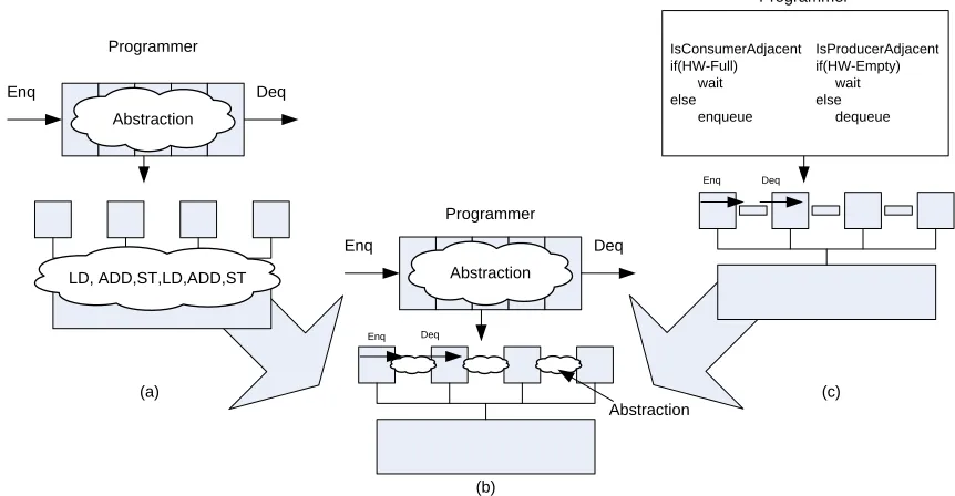
In particular, there is an added dimension of difficulty caused by thread interaction and coordination that must be managed to achieve efficient execution. However, current multicores do not capture these interactions explicitly. Instead, they are decomposed into sequences of instructions whose meaning is tough to decipher at runtime. Consider the case of a queue, as shown in Figure 1.1(a); the abstract meaning to the programmer is clear, but the hardware sees a sequence of instructions involving accesses to shared variables, atomic operations, and possibly fence instructions [21, 25, 19, 27, 31]. Without a significant investment of effort, the hardware cannot understand the kind of interaction taking place.
Recent proposals have addressed some of these problems with efficient abstract operators in hardware [36, 37, 43, 46, 52]. Fig. 1.1(c) shows an example for hardware queues. However, such proposals are usually ad hoc solutions, and often do not provide an effective abstraction. For example, management of chip-level resources within a program or across multi-programmed workloads are left to the programmer to solve some other way; also, system level events, like context switches, are often unsupported or require OS changes. In these cases, the job of the system programmer gets harder instead of easier.
Programmer
Programmer
Enq Deq
Abstraction
LD, ADD,ST,LD,ADD,ST
IsConsumerAdjacent IsProducerAdjacent if(HW-Full) if(HW-Empty) wait wait else else enqueue dequeue
Enq Deq
Deq
Programmer
Enq Deq
Abstraction
Enq
Abstraction
(b)
(a) (c)
Figure 1.1: Multicore Abstraction Gap.
of problems. First, programmers have a difficult time designing algorithms that achieve high performance on a wide variety of multicore architectures and in a wide variety of applications. As cache hierarchies, instruction sets, and on-chip interconnects change, so will the ideal imple-mentation of hardware. The second problem is faced by chip architects. Without a better way to proceed, chip designers are forced to optimize a set of hardware operations that are far removed from the programmer’s abstraction. While these changes are beneficial, such innovations may not lead to clear benefits for the programmer. Instead, software may need to be changed to fully exploit their potential. Therefore,we need to narrow the abstraction gap so that programmers can leverage an efficient and high performing abstraction and architects have a clear and direct
framework for innovation.
In order to narrow the gap, we propose a general architectural design pattern for
ab-stract parallel operations (APOs). We provide to the programmer an interface for an
chip architect how to tolerate system level events (i.e. context switches), how to manage limited hardware resources, and how to account for thread interactions. Our approach manages limited chip resources by allowing instructions in the APO interface to execute in either hardware or software. Robust support of system level events is provided by interpreting the meaning of cache coherence operations on APO structures. Finally, it provides a coordinated strategy for managing thread interaction by arbitrating critical resources transparently in hardware. With this pattern in place, it is easier for architects to designrobust APOs.
To illustrate our design pattern, a design of a single-producer/single-consumer hardware queue is illustrated, which is called an abstract queue operation (AQO). From this detailed design, we have discovered that the size, number, and topology of hardware queues can be abstracted away from the programmer with very little overhead and with no OS level support. This means that the programmer need not be aware that they are using hardware queues at all. Therefore, the architect can directly improve the queue’s behavior because it is an architected concept.
Overall, our work makes the following contributions:
We are the first to propose a general architectural design pattern for integrating abstract
queue operations into multicore architectures. Also, we describe important features of our design pattern, such as how to tolerate system level events (i.e. context switches), how to manage limited hardware resources, and how to account for thread interactions.
We explain how to apply our pattern to single-produce/single-consumer queues.
Using our pattern and by building on top of a recently proposed hardware accelerated
queue (HAQu [28]), we implement an abstract hardware queue in detail; as a result, we discover important novel features of abstract hardware queues.
to a hardware-accelerated queue communicating through memory, our design obtained speedups of 7.9×on our micro-benchmark and 11% on average for our DSWP parallelized codes.
1.3
Published Work
Aspects of this dissertation have been already published.
Efficiently Exploiting Memory Level Parallelism on Asymmetric Coupled Cores
in the Dark Silicon Era, published in January 2012 in ACM Transactions of
Architec-ture and Code Optimization (TACO) special issue on High-Performance and Embedded Architectures and compilers. This work focuses on using asymmetric core configuration to exploit memory level parallelism.
1.4
Organization of Document
Chapter 2
Efficiently Exploiting Memory Level
Parallelism on Asymmetric Coupled
Cores for Single Threaded
Performance
…
while( arcin ){
tail = arcin->tail;
if( tail->time + arcin->org_cost > latest ) {
arcin = (arc_t *)tail->mark;
continue; }
red_cost = arc_cost - tail->potential + head_potential;
if( red_cost< 0 ){
… }
arcin = (arc_t *)tail->mark; }
Figure 2.1: Function price out impl( network t *net) in mcf
2.1
Background
2.1.1 Application Limitations for High Performance
0.00 0.20 0.40 0.60 0.80 1.00 1.20 1.40 1.60 1.80
0 1 2 3 4 5 6 7
De
lay
(
n
s)
Issue Width Issue Queue Size:32
Issue Queue Size:64 Issue Queue Size:128
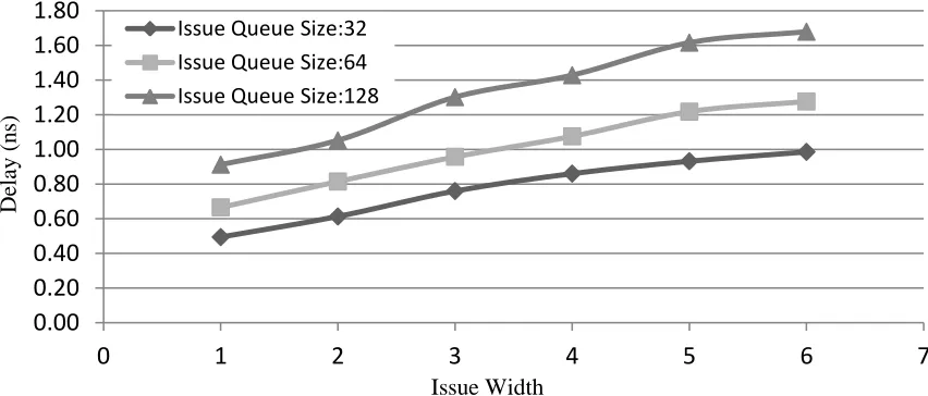
Figure 2.2: Scaling of Issue Queue in terms of delay
2.1.2 Effects of a Core’s Width on Cycle Time
A large instruction window along with a complex microarchitecture might enhance IPC, but at the same time it could increase the clock period. For instance, increasing the size of the issue window and issue width can boost IPC for applications with abundant ILP. However, that may not translate into higher performance because the clock period may increase to accommodate the larger content addressable memory and deeper select tree.
Fabscalar [9], is a state of the art tool that enables architects to synthesize customized designs and evaluate the effects of different designs in terms of frequency, area and power. Using Fabscalar, we can synthesize a Verilog model of an arbitrary superscalar processor and analyze how the size of key processor structures can affect frequency. Figure 2.2 shows the impact of increasing the issue window on the delay of the wakeup-select logic for different issue widths. These assume a 45nm technology and the same input voltage. As we can see from the graph, the smaller the width and issue queue size, the faster the clock frequency can be.
the highest frequency with issue widths of one, two, and four. In our search, we assumed a pipelined architecture with a constant depth andfixed supply voltage, then we varied the issue width and all related microarchitectural structures. We found that the 4-wide core’s maximum frequency was 1.66GHz, the 2-wide core frequency was 2.22GHz and the 1-wide core had a maximum frequency of 2.5GHz (more architectural details can be found in Section 2.4.1). The design search considers all possible timing critical paths of a modern superscalar out-of-order processor, for example wake-select logic, rename logic, cache access time etc. [39], in order to synthesize a processor with a realistic clock frequency. Since we keep the total pipeline depth constant for our exploration, the synthesized core reflects the trade-off between the pipeline complexity and the propagation delay. As in any design space exploration, it is important to search for an appropriate set of designs. Fabscalar considers many circuit-level and architecture-level optimizations, although it is not exhaustive. Therefore, a design team could find other core designs our search did not consider. In general, however, attempts to increase the frequency through microarchitectural complexity do not always have the expected effect on performance, area, or power consumption. In the rest of the chapter, we use the core designs found by Fabscalar.
2.1.3 Checkpointed L2 Miss Processing with Value Prediction: CLP+VP
Speculative Epoch Execution
Mem Latency
L2 Miss
Predict & Checkpoint Core and Cache State
Check Prediction
Check Pred. and Discard Checkpoint
Speculative L1 Data Cache
Checkpoint Core
VPred OPB
CLP+VP Execution Example
(a)
CLP+VP Architecture
(b) Figure 2.3: MLP regions
was incorrect, execution is restored to the checkpoint, the value predictor tables are updated, and the processor resumes from the mispredicted load instruction. In order to avoid recovery in the case of a successful prediction, the L1 cache buffers the speculative state [5]. We will refer to this basic strategy as Checkpointed L2 Miss Processing with Value Prediction(CLP+VP). CLP+VPsupports making predictions on multiple outstanding loads, but only one checkpoint is kept, so any misprediction results in rolling back the entire speculative epoch back to the first predicted load value. Therefore, we adopt CAVA’s mechanisms to prevent aggressive speculative execution through loads which are value predicted with low confidence.
Figure 2.3(b) shows theCLP+VParchitecture with the required Speculative Data Cache [5]. In addition, the OPB is the Outstanding Prediction Buffer. It tracks all outstanding predictions, and if the prediction does not match, the Recovery and Rollback logic is triggered.
2.1.4 Complexity
Design complexity is not easy to measure. Single core techniques are preferable for design com-plexity since modifications are constrained to a single core. However, even single core modifica-tions are increasingly costly in terms of complexity, use of die area, and power as the transistor counts of cores continue to creep up. Previous research has estimated complexity[3] for different components of a processor.
technique, the higher the design complexity will be. This assumes a linear relationship between verification time and transistor count. As such AMP cores offer the unique opportunity to reduce the complexity of a design by implementing a technique on a simpler/smaller core rather than a more complex core. For our cores studied in Section 2.1.2 we can assume that addingCLP+VP on a 2-wide smaller core will have a smaller design complexity than having to add the same technique with larger structures on a 4-wide core.
2.1.5 Core Customization
Core customization is an attractive way of utilizing the real estate of CMPs due to application diversity. Previous research has focused on exploiting applications’ diversity given different cores [23]; however, there have been few studies on core preference for a given architectural technique. Looking at problems such as pointer-chasing and solutions like CLP+VP a question someone might have is what impact this has on core selection for an AMP. There are many factors that make this analysis non-trivial and difficult to anticipate.
The trade-off between core-width and frequency is largely driven by ILP. While MLP and
ILP are not strictly correlated, conventional wisdom argues that MLP tends to come in regions of lower ILP. Hence, this suggests narrower cores may be better.
Latencies to memory are fixed regardless of frequency. Therefore, the frequency of the core
may not matter since the execution time of MLP regions may be ultimately dominated by latency to memory. Hence, the fixed latency to memory suggests that an average sized core – in other words, nothing too fast, and nothing too slow — will work just as well as anything else.
Finally, the accuracy of techniques like CLP+VPto speculate over L2 misses using
Miss Miss
Virtual Instruction Window
Extra Miss
Instruction Window
Instruction Window 4-wide
Core
2-wide Core
Figure 2.4: Virtual instruction window of CLP+VP
narrow cores could be favored.
Through detailed analysis in the next section, we hope to better understand these factors.
2.2
Motivation
2.2.1 Effects of MLP Techniques on Different Cores
One of the benefits of CLP+VP is that it achieves a larger virtual instruction window by speculating over a L2 miss. Figure 2.4 shows the effect that this will have for a 4-wide core and a 2-wide core. The dark solid line cutting the instruction window shows the actual instruction window and how the virtual instruction window will be larger. Regardless of the width both cores will achieve a large virtual instruction window.
Table 2.1: Asymmetric Core Configurations
Label Configuration
Core4 4-wide 1.66GHz Core Core2 2-wide 2.22GHz Core
Core1 1-wide 2.5GHz Core
Core2 CLP+VP 2-wide 2.22GHz Core with CLP+VP Core4 CLP+VP 4-wide 1.66GHz Core with CLP+VP
SCE CLP+VP 4-wide 1.66GHz Core+2-wide 2.22GHz CLP+VP core
Another benefit for a faster clock frequency is when CLP+VPmispredicts a value. In that case, the processor needs to rollback to the checkpointed state and re-execute the instructions. This is done more quickly on a 2-wide core giving a faster recovery time.
2.2.2 Exploring MLP on Different Core Widths
In this section, we investigate the behavior of different core designs, shown in Table 2.1, in code regions sensitive to MLP techniques. Our goal is to establish a relationship between core performance and suitability for exploiting MLP on the same code region. To establish enough data points to draw a strong conclusion about potential for MLP and core preference, we extract code regions of 10K instructions from a dynamic trace of the SPEC CPU 2000 applications and categorize these regions according to their L2 miss rate. Hence, for a wide range of applications, we can average out behavior based solely on the potential for MLP.
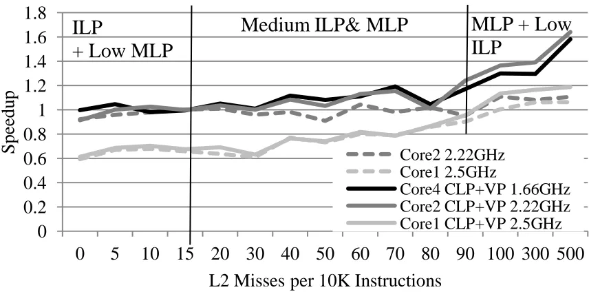
Figure 2.5 plots the performance of theCore2, Core1, Core4+CLP+VP, Core2+CLP+VP, and Core1+CLP+VP designs normalized to the Core4 design. The dashed lines show all the cores without CLP+VP, while solid lines are taking CLP+VP into account. Each bin on the x-axis indicates a different L2 miss rate (L2 misses/10K instructions). Each point on the y-x-axis is the speedup overCore4for all code regions with a specific L2 miss rate. Since these cores have no additional MLP technique, they are only exploiting the MLP available from out-of-order execution.
0
0.2
0.4
0.6
0.8
1
1.2
1.4
1.6
1.8
0
5 10 15 20 30 40 50 60 70 80 90 100 300 500
Spe
ed
u
p
L2 Misses per 10K Instructions
Core2 2.22GHz
Core1 2.5GHz
Core4 CLP+VP 1.66GHz
Core2 CLP+VP 2.22GHz
Core1 CLP+VP 2.5GHz
ILP
+ Low MLP
MLP + Low
ILP
Medium ILP& MLP
Figure 2.5: Performance of different core widths normalized to Core4
has no to very few misses. Most high ILP applications spend the majority of their execution in this region (98% for ammp). In this region 4-wide core designs have a clear advantage due the high ILP exploited by the width of the cores. The second region is identified asMedium ILP& MLP. In this region we see that ILP is diminished somewhat by the increasing number of L2 misses. Applications executing on the 4-wide cores (Core4andCore4+CLP+VP) are faster than Core1, and Core1+CLP+VP. However, we also see that designsCore2, and Core2+CLP+VP are competitive. When comparing the 2-wide core designs to the 4-wide cores, we can consider the 2-wide cores a better design due to the power savings of a smaller core (for an explanation on how higher frequency can save on power see section 2.4).
The third region identified as MLP+ Low ILPis the most interesting region. We see that the 2-wide core designs gain a slight advantage. In Figure 2.6b we show the actual IPC and instructions per second (IPS) for the 100 L2 miss bin. These regions have high amounts of L2 misses per sampled region. What is also interesting is that here we see clearly the core width versus core frequency trade-off.
0% 50% 100%
1
11 21 31 41 51 61 71 81 91 101 111 121 131 141 151 161 171 181 191
Instruction Issue Distance for L2 Misses
10Misses 50Misses 100Misses
(a) Issue Distance of L2 misses
0 1 2
IPC IPS
Core4 Core2
(b) IPC vs IPS
Figure 2.6: Performance versus MLP potential
execution time (regular instructions would complete while misses are being serviced), and since the time to access main memory is constant, the cores should perform the same. However, this is not the case. Figure 2.6a shows on the x-axis the distance between issued instructions which miss in the L2. On the y-axis we have the total percentage of load instructions which have an issue distance of ’x’ or less from a previous L2 miss. The three lines represent different L2 miss rate bins from Figure 2.5. From this graph, it is clear that regardless of the amount of L2 misses in every 10K bin, L2 misses cluster close together. This clustering is important for two reasons. First, it explains why MLP techniques can benefit sequential performance. Second, clustering shows us that execution time for these bins is actually composed of memory access regions and non-memory access regions. The conventional wisdom fails to account for application and core-level effects in regions of high L2 miss rates, however, our analysis does account for them. Therefore, we see that the MLP+Low ILPregion can exploit asymmetry.
0
0.2
0.4
0.6
0.8
1
1.2
0
5
10 15 20 30 40 50 60 70 80 90 100 300 500
P
er
cent
ag
e
Ov
er
E
n
tir
e
E
x
ecut
io
n
L2 Misses per 10K Instructions
Overall
mgrid
mcf
bzip2
Figure 2.7: Percent of Total Execution Spent in Different L2 Bins
2.3
Symbiotic Core Execution
The goal is to design an AMP which can identify MLP regions on the fly and schedule execu-tion to the best available core. To do this, we propose Symbiotic Core Execuexecu-tion (SCE). The term symbiosis is borrowed from biology: two self sufficient organisms exist symbiotically when they survive better together than when alone. Symbiosis is a compelling description because it identifies the cores as being independent and capable of working alone, as is often needed in a multiprocessing environment. However, when necessary, they can be used together for a greater performance advantage.
2-Wide MLP 4-Wide
ILP
32K L1
16K L1
2MB L2
Memory
Tile View (a)
AMP View (b) Tile 1 Tile 2
Tile 3 Tile 4
Figure 2.8: Architecture of Tile and AMP
algorithm.
2.3.1 Overall Architecture
SCE’s mechanism is implemented on a homogeneous ISA, heterogeneous tile CMP. Figure 2.8(a) shows an example SCE tile and Figure 2.8(b) shows the homogeneous-tile CMP implementation. Due to power constraints and the large areas of a chip that will have to remain powered off in the near future [13], we can power on only one core of the tile at a given time. We refer to this as SCE mode. In SCE mode, the OS sees one logical core per tile, and hardware can initiate fast context switching among the symbiotic cores. In the case where the number of threads is more than the number of cores per tile, we assume that SCE is disabled, and the chip can enable different combinations of types of cores to fit applications’ needs for a given power budget. Scheduling applications in this case would be similar to previous work such as [23].
the reorder buffer, the processor squashes the remaining instructions, and performs the context switch between the cores by copying the register file from one core to the next. We design the context switch to begin as soon as the head of the ROB stalls by a long latency instruction. That way, the context switch delay is overlapped by the servicing of an L2 miss. Once the context switch is finished, execution is resumed. If we switched because of a long latency instruction at the head of the re-order buffer, then that instruction is re-executed.
Our hardware level context switch happens only during SCE mode. Furthermore, the idle core will always be available, so our context switch mechanism can be fast. Even though we have hardware support for switching, many overheads may be incurred on a switch, such as cache warm-up penalty, cache invalidations, effects on the TLB, and poor branch predictor history. These effects are one reason why building an efficient SCE scheduler is important.
2.3.2 SCE Mode Scheduling
Our goal is for SCE mode scheduling to work well for a wide range of applications but espe-cially for those that contain significant amounts of MLP. This is challenging because there are hierarchical, competing concerns. At the Core-level, we do not know a priori which node will usually provide the best performance. We must determine apreferredcore on the fly. Further-more, this preferred core can change throughout execution. As a result we must adapt to the coarse-grained phase of the running application. In addition, at the fine-granularity of MLP phases, we will switch to the MLP core to exploit its MLP technique, and we must switch back to the preferred core in regions of low ILP. Failure to identify a good start or end to the MLP region could take the application away from its preferred core for too long. Finally, even within MLP epochs, the MLP technique should be used only when it can actually provide a performance benefit. A good scheduling algorithm will manage all of these concerns.
2.3.3 Preferred Core Scheduling
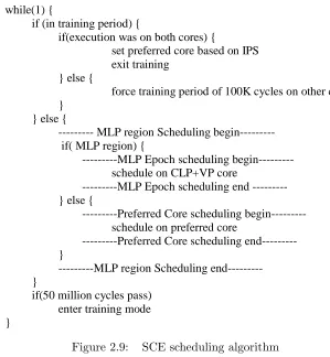
Figure 2.9 shows pseudocode for our overall core scheduling strategy. Because we wish to choose the best core even when not in an MLP region, much of the code is concerned with picking the preferredcore. Overall, the algorithm is divided into training mode and non-training mode.
Every 50 million cycles (25-30ms depending on the core), our algorithm enters training mode and picks a new preferred core. A typical operating system time slice would range from 5ms to 100ms [29]. Scheduling at the operating system time slice enables the scheduling mechanism to capture possible context switches and the effects they can have on performance. We also selected 50 million cycles in order to have a large enough period for our preferred core scheduling policy to not execute frequently while at the same time small enough to allow for many complex phase behaviors to be see. Reducing the frequency would also have an impact on executing on an incorrect core for a period of time. An alternative to this scheduling mode could be using a phase change detection mechanism similar to [47].
The first if-condition controls the actions during training mode. For each core in the AMP tile, we run for a minimum of 100K cycles and record the instructions per second (IPS) in a hardware register. Note, we must use IPS to account for different operating frequencies. Once all cores in the tile have been trained, we select the core with the highest IPS. Note that we do not disable the MLP technique when training on the MLP core. While this may distort the IPS compared to running without the MLP technique, it usually does not alter the preferred cored decision.
When not in training mode, non-MLP regions will run on the preferred core by default until an MLP region is encountered. When we enter an MLP region, execution switches to the MLP core. As long as the MLP region is active, execution remains there. However, once the MLP region ends, execution returns again to the preferred core.
while(1) {
if (in training period) {
if(execution was on both cores) {
set preferred core based on IPS exit training
} else {
force training period of 100K cycles on other core }
} else {
--- MLP region Scheduling begin--- if( MLP region) {
---MLP Epoch scheduling begin--- schedule on CLP+VP core
---MLP Epoch scheduling end --- } else {
---Preferred Core scheduling begin--- schedule on preferred core
---Preferred Core scheduling end--- }
---MLP region Scheduling end--- }
if(50 million cycles pass) enter training mode }
Figure 2.9: SCE scheduling algorithm
application always benefits from being on the MLP core, this algorithm will ensure that it is never scheduled off that core except for short regions of training. However, it critically relies on judicious MLP Region detection. If MLP regions are triggered too frequently, it can add significant overhead and hurt performance. In the next section, we consider the design of the MLP Region Detection policy.
2.3.4 MLP Region Detection
Responsive switching to MLP core
MLP Region
Ninst
L2 Misses L2 Misses > rmiss* Ninst
Preferred Core
Nstay Switch
1st Miss Completes
Switch Penalty
MLP Core
Figure 2.10: Responsive Switching to MLP Core
average, we see the crossover point at 10 L2 misses per 10K instructions. So, as a heuristic, we assume that we need to observe misses at that rate in order for the MLP core to be profitable. We identify this rate asrmiss. We usermiss to identify the minimum number of L2 misses that should be observed in a region ofNinst instructions in order to switch cores.
For each contiguous chunk ofNinst instructions, our scheduler counts the number of misses. If fewer thanNinst×rmiss misses are observed at the end of the region, the counter is cleared. As soon as Ninst ×rmiss misses are observed, the application is switched to the MLP core. Figure 2.10 illustrates this policy.
MLP Core
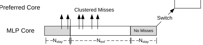
Nstay Next
Clustered Misses
No Misses
Nstay
Preferred Core
Switch
Figure 2.11: Lazy Switching to Preferred Core
Lazy Switching back to the Preferred Core
Once running on the MLP core, our scheduler evaluates a) if it was a correct decision to switch and b) if there is no longer a benefit from MLP. It is important to remain on Core2+CLP+VP long enough to exploit any MLP. However, it is desirable to correct erroneous decisions before too much time elapses.
Since L2 misses cluster, if the application is entering a region of clustered misses, we expect an elevated miss rate. We define Nstay as the number of instructions that must be executed on the MLP core; during that region, an L2 miss must be observed. If no misses are observed, it is likely that clustering is not present (or no longer present) and execution should return to the preferred core. However, if a single miss is observed, we remain on the core for an extended execution, Next. At the end of the extended region, we perform the same evaluation again. Figure 2.11 illustrates this policy. We found that Ninst = 3000, Nstay = 700 and Next = 3000 work well. Note the rate of L2 misses required to switch back to the preferred core is lower than that required to switch away. Our scheduling policy is more sensitive to the Ninst and rmiss parameters.
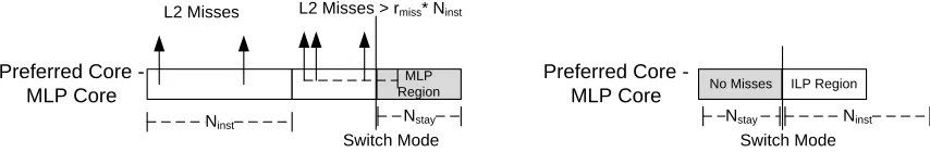
MLP Core is Preferred Core
MLP Region
Ninst
L2 Misses L2 Misses > rmiss* Ninst
Preferred Core - MLP Core
Preferred Core -
MLP Core No Misses ILP Region
Nstay
Nstay Ninst
Switch Mode Switch Mode
Figure 2.12: SCE scheduling for MLP being the preferred core
between modes seamless.
2.3.5 MLP Epoch Scheduling
Previous work has shown that MLP techniques need to be smart on how speculation is per-formed on L2 misses [34, 5]. In order forCLP+VPto be effective, the value prediction must be accurate in order to avoid polluting the cache and fetching instructions down the wrong path. We use a last-value predictor indexed by a hash of the PC and the branch history and we use a confidence estimator with a two-bit saturation counter indexed by the PC, just like in [5]. If the confidence on a prediction is too low, we do not speculate. Furthermore, we geometrically accumulate the confidence estimate for all the speculative load values created during an epoch. Once the accumulated confidence drops below a threshold, we stop speculating.
Another source of inefficiency is speculating over the shadow of an L2 miss that overlaps with no other L2 misses. If running on the ILP core (when it is the preferred core), this inefficiency is prevented because we are unlikely to switch to the MLP core for isolated L2 misses. When we are on the the MLP core, we avoid speculation because our value prediction confidence estimator will eliminate solitary misses with low prediction accuracy.
2.4
Evaluation of SCE
2.4.1 Experimental Setup
Table 2.2: Core Details. Cycle counts are in processor cycles
Core Setup Multicore Single Core Multicore Single Core Multicore Single Core Origin Fabscalar Scaled Peak Fabscalar Scaled Peak Scaled Peak Fabscalar Frequency 1.66 GHz 1.68 GHz 2.22 GHz 2.31 GHz 2.30 GHz 2.5 GHz
Fetch Rate 6 4 2
Issue Rate 4 2 1
Retire Rate 4 2 1
ROB 128 96 64
LD/ST Queue 54/38 42/38 36/24
Mem/Int/Fp Units 2/3/2 2/2/2 1/1/1
Main Memory RT 184 cycles 186 cycles 246 cycles 256 cycles 255 cycles 277 cycles Core Switch Delay 37 cycles 50 cycles 55 cycles
Area(mm2) 1.636 1.118 0.718
Pipeline: 3-cycle fetch, 1-cycle decode,1-cycle Rename, 1-cycle dispatch,2-cycle issue, 2-cycle issue, 1-cycle RegRead, 2-cycle Mem/Int/Fp Units,1-cycle DataCache, 1-cycle writeback, 1-cycle retire Core4 Cache: IL1 and DL1: Size=32KB; Assoc=4-way; Line size=64B; RT=3 cycles
Core2 Cache: IL1 and DL1: Size=16KB; Assoc=4-way; Line size=64B; RT=3 cycles Shared L2 Cache: Size=2MB; Assoc=8-way; Line size=64B; RT=10 cycles
BTB: size=2K; Assoc=2-way, Supply Voltage= 1.1V, Tech=45nm
Branch predictor: bimodal size=16K; gshare-11 size=16K; Branch Mispred. Pen.=14 cycles H/W Pref.: 16-stream stride prefetcher; hit delay=8 cycles; buffer size= 16KB
SCE param.:Nstay=700cycles,rmiss=0.001 andNext=3000cycles
CLP+VP configuration: OPB = 128 entries Max. Outs. preds./Instr.=512/3072 BHLV+GLV predictor, table size=4096 entries each
GCC 4.4 [16] with -O3. Our simulations use the ref inputs set. We skip the initialization stage of applications and simulate at least 600 million correct instructions for SPEC2000 and 300 million for SPEC2006. We used as many of the SPEC2000 and SPEC2006 as we could to guarantee a mix of applications with both low-MLP and high-MLP behavior; also, some were excluded due to limitations of the cross-compiler or simulator.
We also used the FabScalar framework [9] to weigh the cost of different superscalar designs in terms of clock period, area, and power (static and dynamic). The FabScalar framework synthesizes Verilog models of arbitrary superscalar processors, where each superscalar processor can be customized in terms of pipeline ways (width of the processor) and sizes of the memory structures within a stage.
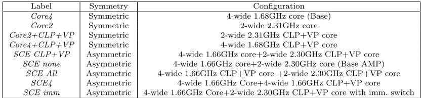
consump-Table 2.3: Core Configurations
Label Symmetry Configuration
Core4 Symmetric 4-wide 1.68GHz core (Base)
Core2 Symmetric 2-wide 2.31GHz core
Core2+CLP+VP Symmetric 2-wide 2.31GHz CLP+VP core
Core4+CLP+VP Symmetric 4-wide 1.68GHz CLP+VP core
SCE CLP+VP Asymmetric 4-wide 1.66GHz core+2-wide 2.30GHz CLP+VP core
SCE none Asymmetric 4-wide 1.66GHz core+2-wide 2.30GHz core (Base AMP)
SCE All Asymmetric 4-wide 1.66GHz CLP+VP core +2-wide 2.30GHz CLP+VP core
SCE4 Asymmetric 4-wide 1.66GHz Core+4-wide 1.66GHz CLP+VP core
SCE imm Asymmetric 4-wide 1.66GHz Core+2-wide 2.30GHz CLP+VP core with imm. switch
tion by doing SPICE level simulation.
We used Synopsis Design Compiler C2005.09-SP3 and Cadence SoC Encounter V7.1, using the FreePDK OpenAccess 45nm Standard Cell Library [50] to synthesize our different designs in order to estimate timing, power and area. SESC supports power modeling and we feed the power characteristics of each structure with data from Fabscalar. To keep the design space within limits, we do not modify the voltage supply, which could affect frequency, and restricted the total pipeline depth to 14 (from Fetch to Commit) for all compositions of the processors used in the evaluation. We believe that a 14-deep pipeline is appropriate, since it can also be found in contemporary high performance microprocessors [53].
2.4.2 Power Modeling
Since we allow different core designs to operate at different frequencies, it is important to care-fully consider trade-offs in terms of power and performance in our evaluation. In this section, we describe the methodology for calculating the operating frequencies of each core in all simulated configurations.
PDynamic=αCV2F (2.1)
The peak power is calculated much like PTotal except that an average switching factor is replaced with the worst case dynamic load for the chip. When running on an SCE configuration, the peak power is:
PPeakSCE= Max(PDynP eakCore2, PDynP eakCore4) +PStaticCore2 +PStaticCore4+PPeakAllElse (2.2)
Since it is the case that PDynP eakCore2 < PDynP eakCore4, the equation can be simplified to only consider the peak dynamic power of Core4. Also, PPeakAllElse is the remaining dynamic and static power from interconnect and cache. Compared to a single Core4 design, we have added extra leakage power.
In order to make a fair comparison, we set the peak power of the chip to that of the SCE configuration. Since the single core configurations cannot reach this peak power, we use the Fabscalar tool to identify a scaled voltage and frequency that boosts their power consumption to match the peak power of the SCE configuration. Interestingly, we use this same technique to provide our own design an advantage. When running on Core2, the peak power is over-estimated by the difference in PDynP eakCore2 and PDynP eakCore4. Hence, SCE can also exploit scaled voltage and frequency when running on the smaller core.
Dynamic Core4, 74.71% Dynamic 32K L1, 1.10% Dynamic 16K L1, 0.98% Dynamic 2M L2,
18.00% Leakage Core4+L1, 0.74% Leakage Core2+L1, 0.67% Leakage L2, 3.80%
(a) SCE Core4 Execution Peak Power Dynamic Core2, 61.71% Dynamic 32K L1, 1.10% Dynamic 16K L1, 0.98% Dynamic 2M L2,
18.00% Leakage Core4+L1, 0.74% Leakage Core2+L1, 0.67% Leakage Core2+L1, 3.80% Unused PeakPower, 13.01%
(b) SCE Core2 Execution Peak Power Dynamic Core4L1, 74.71% Dynamic 32K L1, 1.10% Dynamic 2M L2,
18.00% Leakage Core4+L1, 0.74% Leakage L2, 3.80% Unused PeakPower, 1.66%
(c) Single Core Core4 Execution Peak Power
Figure 2.13: Power breakdown of each component in a multicore
peak power when executing onCore4 versusCore2 on SCE is 13.01%; this is primarily due to the difference between the dynamic power for a 4-wide core compared to a 2-wide core. Hence, when executing on Core2 during SCE, the voltage and frequency can be scaled to consume 13.01% more dynamic power.
Table 2.2 shows the resulting frequencies in our experiments. The Fabscalarcolumns show the frequency reported by the Fabscalar tool. This is used forCore4 in SCE mode. TheSingle Core Scaled Peak column shows the adjustment to frequency when running on a single core (no SCE). Finally, the Multicore Scaled Peakcolumn shows the adjustment to frequency when execution is on Core2 in SCE mode.
Table 2.2 shows the SESC configuration parameters used in our experiments. Labels used in the graphs are explained in Table 2.3 along with the configurations executed.
2.4.3 Performance Compared to Symmetric Multicore Processors
0 0.2 0.4 0.6 0.8 1 1.2 1.4 1.6 1.8
Core2 Core2 CLP+VP Core4 CLP+VP SCE CLP+VP
Sp
ee
d
u
p
o
v
er
B
ase
SPEC 2000 SPEC 2006
2.01 2.03 2.04
Figure 2.14: Speedup for SCE CLP+VP, Core2, Core2 CLP+VP, and Core4 CLP+VP nor-malized toCore4
MLP and low value prediction accuracy during the MLP regions.
When compared to a single core with the CLP+VP technique, we see that our design is better. SCE CLP+VP is better than Core4 +CLPVP by 5.3% and 6.6% for SPEC2000 and SPEC2006 applications, respectively, with a maximum of 14.5%. The benefits come from the faster 2-wide CLP+VP core achieving better performance than the 4-wide CLP+VP for high MLP regions and the use ofCore4to complement 2-wide CLP+VP core’s for regions of low to no MLP.
Although not included here for brevity, we also performed an experiment in which the 2-wide core in SCE CLP+VP does not use the Scaled Peakfrequency, rather it uses the Fab-scalar reported frequency. In this configuration,SCE CLP+VPperforms marginally worse than the Scaled Peak SCE CLP+VP configuration (roughly 1.5% worse on SPEC2000 and 1% on SPEC2006), but the overall performance trend remains.
2.4.4 Power and Energy Delay2
0.00 0.50 1.00 1.50 2.00
Core4 CLP+VP Core2 CLP+VP SCE CLP+VP
No
rm
alize
d
to
B
ase
P
o
w
er
SPEC 2000 SPEC 2006 2.1 2.0
Figure 2.15: Power for SCE CLP+VP, Core2, Core2 CLP+VP, and Core4 CLP+VP normal-ized to Core4
and invalidations triggered by the coherence protocol. The graphs show, our SCE CLP+VP design consumes less power compared toCore4+CLP+VP by 18.9% and 15.6% for SPEC2000 and SPEC2006, respectively. SCE, does require more power than Core2+CLP+VP, but this is a direct consequence of using Core4 to accelerate some non MLP regions. For benchmarks with high MLP regions such as mcf and equake, we see that average power is higher on the Core2+CLP+VP thanCore4 due to speculation and re-executed instructions.
Figure 2.16 displays the energy delay2for each configuration. Overall,SCE CLP+VPreduces the energy delay2 by 20.1% and 23.1% for SPEC2000 and SPEC2006 benchmarks overCore4. When compared to theCore4+CLP+VPdesign, the energy delay2savings are 18.3% and 21.1% for SPEC2000 and SPEC2006, respectively. Note thatequake, mcf, swimandgccare particular advantageous when considering energy delay2 because their high performance offsets their high power consumption. An interesting observation here is that on average 56% of the average power is from dynamic power while the remaining 44% is due to static power.
2.4.5 Performance Compared to Asymmetric Multicore Processors
0.00 0.25 0.50 0.75 1.00 1.25 1.50
Core4 CLP+VP Core2 CLP+VP SCE CLP+VP
No
rm
alized
to
B
ase
En
er
g
y
Delay
2
SPEC 2000 SPEC 2006
Figure 2.16: Energy Delay2 for SCE CLP+VP, Core2, Core2 CLP+VP, and Core4 CLP+VP normalized to Core4
1.66GHz frequency neither of which haveCLP+VP; the 2-wide is used for MLP regions.SCE4 has a 4-wide base core along with a 4-wide CLP+VPcore for the MLP regions. Finally, SCE immis our SCE core configuration with a scheduler which switches to the MLP core at the first L2 miss (as opposed to using L2 miss rate likeSCE CLP+VPdoes).
Figure 2.17 shows the speedup of each design compared to the Base AMP design, shown asSCE none. Overall, our design is 4.7% and 3.3% better for SPEC2000 and SPEC2006 when compared to the base AMP with no MLP technique implemented. Our SCE design is also better than SCE4 by 4.8% and 8% for SPEC2000 and SPEC20006. When comparing against SCE immwe see thatSCE CLP+VP’s performance is better by 6.3% and 9.9% over SPEC2000 and SPEC2006. This is an important indicator to why our scheduling mechanism is effective. It shows how the miss rate is more accurate for detecting MLP regions, than making scheduling decisions solely based on a single L2 miss.
0 0.2 0.4 0.6 0.8 1 1.2 1.4 1.6 1.8
SCE CLP+VP SCE All SCE4 SCE imm
Sp
ee
d
u
p
o
v
er
B
ase
A
M
P
SPEC 2000 SPEC 2006
Figure 2.17: Speedup for SCE all, SCE none, SCE4, and SCE imm normalized toSCE none
select a customized core and only implement it there. On the other hand, if an MLP technique is cheap, add it everywhere. In either case, you get the best performance due to our effective hardware scheduling mechanism which exploits core-level differences.
2.4.6 SCE Execution Analysis
Table 2.4 displays details on the switching overhead for our SCE proposal. TheOverheadcolumn indicates the overhead due to switching cores. Our scheduling mechanism can overlap most of the context switch with L2 misses when switching between Core4 to CLP+VP. This explains why, out of the total overhead, the migration to the MLP core contributes an average of 24%. One more source of overhead is the invalidation of shared cache lines that are a result of switching cores. We have not measured this, but we modeled it in our simulations.
Table 2.4: Characterizing SCE: Total overhead of switching over entire execu-tion, scheduling accuracy and value predictor accuracy
Total Sched. Value Benchmark Overhead Acc. Pred Acc.
ammp 0.31% 96.13% 24.75%
applu 0.02% 82.43% 34.76%
bzip2 0.02% 86.67% 9.94%
crafty 0.51% 82.87% 78.55% equake 1.13% 96.80% 47.10%
gap 1.12% 95.78% 90.91%
gzip 0.07% 96.85% 4.04%
mcf 1.07% 99.78% 49.09%
mesa 1.42% 89.86% 88.01%
mgrid 0.02% 74.08% 15.13% parser 1.98% 93.83% 74.88%
swim 0.05% 91.45% 3.70%
twolf 0.74% 94.43% 44.31% vortex 0.36% 87.98% 59.88%
vpr 0.91% 95.95% 22.22%
wupwise 1.78% 85.00% 44.00% perlbench 0.02% 90.00% 12.58%
gcc 0.97% 94.51% 48.84%
milc 1.43% 93.34% 57.47%
gromacs 0.28% 83.10% 46.81% gobmk 0.86% 91.43% 68.33%
namd 0.35% 89.86% 44.40%
Table 2.5: Characterizing Execution in SCE Mode: Percent of execution spent on Core4and Core2+CLP+VP in SCE mode
Benchmark Core4 Core2+CLP+VP
ammp 32% 68%
applu 78% 22%
bzip2 92% 8%
crafty 78% 22%
equake 07% 93%
gap 23% 77%
gzip 06% 94%
mcf 05% 95%
mesa 83% 17%
mgrid 72% 28%
parser 48% 52%
swim 12% 88%
twolf 11% 89%
vortex 83% 17%
vpr 90% 10%
wupwise 11% 89%
perlbench 47% 53%
gcc 12% 88%
milc 26% 74%
gromacs 58% 42%
gobmk 81% 19%
namd 69% 31%
dealII 92% 8%
soplex 24% 76%
0.93 0.94 0.95 0.96 0.97 0.98 0.99 1 1.01 rmiss 0.01 rmiss 0.023 rmiss 0.06 Nstay 300 Nstay 1000 Nstay 3000 Next 1000 Next 10000 N om ralize d t o N ext 10 K
Scheduling Sensitivity
Figure 2.18: Sensitivity to scheduling parameters.
Table 2.4 also displays the accuracy of our scheduler and the value predictor for our CLP+VP. Overall our scheduling mechanism’s accuracy is high. Value prediction accuracy is also interesting since low accuracy does not necessarily translate to low performance. Even for high MLP regions, when the value prediction is wrong, useful prefetches can generate enough MLP to improve performance during the re-execution of instructions. Finally, Table 2.5 shows the time spent on Core4and Core2+CLP+VP in our SCE design. As we can see here, bench-marks with huge gains spend the most time on the MLP core.
2.4.7 Sensitivity to Scheduling Parameters
0 10 20 30 40 50 60 70
Core4+CLP+VP Core4+CLP+VP+SCE Scheduling
In
cr
ea
se
in
E
x
ec
u
te
d
I
n
structio
n
s
(%)
SPEC 2000 SPEC 2006
Figure 2.19: Increase in executed instructions fromCLP+VPvs benefit of MLP region schedul-ing
meet the minimumrmiss rate decreases and forces applications to migrate back to the preferred core sooner. The performance can degrade across benchmarks by 1.9% for anNstay of 300. We found that our scheduling mechanism is not very sensitive to Next. We see that reducing it by 3 resulted in a decrease across benchmarks of 0.7%.
2.4.8 MLP Region Scheduling Benefits on CLP+VP
2.5
Related Work
2.5.1 Memory Level Parallelism
Although we are in the era of CMPs, sequential performance is important. Lots of research has focused on designing processors that attack the memory wall by increasing the program’s MLP. Prefetching in the form of helper threads is a technique used to extract MLP [10, 32, 14]. Execution of the helper thread is done in-parallel on a SMT, or on a separate core for CMP architectures. Other techniques such as WIB[26], CFP[49], KILO[11], and BOLT[20] focus on increasing the window size by unblocking the pipeline on cache misses, thereby increasing the MLP. In these techniques long-latency operations (and dependent instructions) are removed from the scheduling window and inserted to buffers, thus freeing resources. When the latency is resolved the instructions are reinserted into the scheduling window. Runahead execution [34, 12], CAVA [5], and Clear [22] tolerate the long latency of L2 misses by retiring the load instruction when it reaches the head of the ROB and continuing execution despite the fact that the load has not completed. When the memory request returns it re-executes the instructions or if the value was correct, it continues execution. Chou et al. [8] evaluates the effectiveness of out-of-order execution on MLP compared to in-order processors as well as the effectiveness of value predictors, branch predictors and runahead execution in extracting more MLP. Our work contributes to how an MLP technique could be added to an AMP.
2.5.2 Asymmetric Multicore Processors
Asymmetric Multicore Processor designs have been proposed as a solution to achieve higher performance per watt ratio for executing a wider range of applications [23, 4, 51]. This does not always result in improved performance over a homogeneous system for single threaded applications. Given the same area, previous proposals [51, 4, 23, 45] achieve performance im-provements when scheduling between cores at the multi-application or multi-thread level. No previous proposal has suggested that fine grain scheduling can achieve performance benefits, while only using one core at a time and running one version of the application, which is what our scheme provides.
Recent work on AMPs designed for MLP is presented by Pericas et al. [40]. In this work, an AMP design is composed of a fast cache core and a small in-order memory core to exploit high and low locality code respectively. By coupling the cores together an increased instruction execution window is created. Our approach is different in that we use fully functional cores which can work independently if needed. Execution is also always on one core rather than spread across cores.
Other recent AMP proposals use a slipstream[35, 55] inspired design to speedup sequential performance . These techniques however require execution of the same application on multiple cores concurrently, or require recompilation of the applications to create a reduced version of the program that will work as a perfect predictor or prefetcher [15].
2.6
Discussion and Summary
2-wide issue width, were more effective at exploiting Checkpointed L2 Miss Processing than a wider 4-wide issue core — providing better performance and energy efficiency across the MLP continuum. Therefore, we conclude that customization for MLP is important on an AMP.
We leveraged this finding to support Symbiotic Core Execution on an AMP. SCE is an effective scheduling mechanism because it allows MLP regions to exploit the higher performance and better power efficiency of the customized core while still leveraging the benefits of other cores during regions with little to no MLP. Using SCE, we achieve performance improvements of 5.3% and 6.6% for SPEC2000 and SPEC2006, respectively, with a maximum speedup of 14.5%. For the same study, it achieves a 18.3% and 21.1% energy delay2 reduction for SPEC2000 and SPEC2006, respectively.
Chapter 3
Improving Fine-Grain Thread Level
Parallelism Using Abstract Queue
Operations on Multicores
This chapter presents abstract queues and their use to improve fine-grain thread level par-allelism. It is organized as follows: Section 3.1 presents our abstract operations properties; Section 3.2 describes the architecture of AQO. Section 3.3 provides the experimental setup and the full evaluation in the context of micro-benchmarks and DSWP. Section 3.4 discusses related work, and Section 3.5 summarizes the chapters contributions.
3.1
Bridging the Multicore Abstraction Gap
3.1.1 Properties of Abstract Parallel Operations
D E M U X
Data Structure
Interface
Abstract API Instructions
Library Calls
Logic
Micro-ops -- Software
Figure 3.1: Scaling of Issue Queue in terms of delay
is abstract, hence the organization of the structure is hidden from the programmer.
An APO provides an operation meaningful to parallel programmers. The interface of the APO must have clear and well defined semantics, both in terms of its functional meaning but also as it relates to ordering of events in the processor. Since programmers often deal directly with the ordering of references to variables, APOs should have clearly stated semantics with respect to loads and stores. Ideally, the APO will adopt rules consistent with the memory consistency model of the chip.
Finally, for all instructions in the APO interface, we assume that a software equivalent is available. We do not assume it must be efficient, but it must correctly implement the abstraction. Since most APOs were first developed in software, it is likely that they both exist and have efficient implementations for some usage scenario. We use this requirement to make software and hardware work interchangeably on the APO. Note, this allows us to begin an APO operation in hardware and finish it in software if interrupted in the middle by a system level event (e.g. context switch).
Core Memory
APO Data Structure
(DS)
APO FU APO DS$
Data L1
Data L2
Core APO FU APO DS$
Data L1 APO Logic and
Arbiter
Figure 3.2: APO Design Pattern.
while the details of the implementation are hidden inside the architecture. During execution, instructions in the interface can execute either in custom logic or in a sequence of micro-ops that are equivalent to the software algorithm. However, both implementations use the data structure to carry out their operation.
modifica-tion. To accomplish this goal, we leverage cache coherence explicitly, since it has already been designed to work seamlessly with virtual memory and all OS events.
Architectural Description
Now we consider the architectural components for the pattern, as shown in Figure 3.2. While not a physical architectural component, the APO Data Structure (DS) is the connection between the software and hardware. This data structure is allocated in memory by the programmer (e.g. using malloc) and initialized to contain essential information needed for the hardware to implement the APO. An API exposed to the programmer can see to its allocation and initialization. The hardware is designed with innate knowledge of the structure and how to operate on it.
Any hardware implementation of the APO must use this data structure and keep it cache coherent. To do so, an APO Data Structure Cache (DS$) is added to each core. This cache stores the relevant information from the APO DS close to the core and maintains coherence on the lines. Therefore, it is important that the DS be created in such a way that it is cache friendly. The DS may be specific to a single kind of APO in order for architects to be able to control the design of the structure and tailor it to a specific chip’s architecture under-the-hood. Since the DS$remains coherent, we have no concern about its contents being lost or becoming stale due to system level events. However, an APO may have to interpret coherence events on the DS$in a special way. We will discuss this more later (Section 3.2.2).
instruc-Table 3.1: Applying Architectural Design Pattern to Abstract Operations.
Abstract Operation Queue
Application setup(Qptr,Buffer,Size) Programming enq{b,h,w}Rs, QPtr Interface deq{b,h,w}Rd, QPtr
Hardware Hardware Queues between cores Implementation or through memory [28]
Arbiter Identify core-core communication and map to queue or memory
tion using a software version held in micro-code (or it could use custom logic that was always available without arbitration).
Finally, an Arbiter/Selector interfaces with the DS$ and APO FU to choose a hardware resource for the operation. Since APOs involve multiple threads, arbitration and selection logic must consider the behavior of all threads participating in the APO. For a Single-Producer/Single-Consumer (SPSC) queue, this would only consist of two threads.
3.1.3 Examples
Table 3.1 illustrates how we envision the API, hardware implementation and arbitration of our design pattern for APOs. This example is meant to show the generality of our design pattern. Just to reiterate, we believe having such a common framework is important for enabling innovation on multicores.