A Comparative Analysis of PID and FO-PID
Controller on PMDC Generator
Manik Dogra
1, Lini Mathew
2Assistant Professor, Govt. Hydro Engineering College, Bandla Distt. Bilaspur Himachal Pradesh, India1 Professor and Head,Department of Electrical Engineering, NITTTR, Chandigarh, India2
ABSTRACT: Feedback based control system nowadays is mostly employed technique in modern control systems. PID based feedback control is one of the most popular and widely used controller in 90% of the control loops. However, due to limited degrees of freedom in PID control system under various uncertainty conditions, these PID controllers have low performance. Fractional–order PID controllers extend the capabilities of a conventional PID controller and is considered to be an effective approach for a wide variety of applications in process control. This paper demonstrates the real-time implementation of PID and FO-PID controllers on a PMDC generator. Also, the comparative analysis of both the approaches have been carried out in terms of output voltage generated by the PMDC generator with different parameters for PID and FO-PID controllers.
KEYWORDS:Feedback control, PID, FO-PID, Brushless DC Motor, PMDC Generator
I. INTRODUCTION
A controller is generally a device that is used in Industrial process control systems to regulate the behaviour of any process in order to get the desired response. Since the invention of PID control in 1910 (largely owning to Elmer Sperry’s ship autopilot), and the Ziegler–Nichols’ (Z-N) straight forward tuning methods in 1942 [1], the popularity of PID control has grown tremendously. Today, the PID controllers are the most sought after feedback controllers used in more than 90% of industries. The main requirement of all the controllers is to design them in such a way so that the process variables are always close to desired value [2-3]. Recently, many researchers have worked on the tuning of different structures of PID such as IPD and D-PI and found that Zeigler Nicholas is only applicable on parallel PID structure and the Z-N method rules should be refined to apply to other structures [4].Then with the advent in the research of artificial intelligence. Techniques, researchers started implementing fuzzy PID controller and its various configurations like hybrid and TI, SI etc. which gave better performance than the classical PID controller [5-6]. Swarm type like PSO or physics and chemistry inspired optimization techniques based on the source of inspiration for such algorithms to reach their global best [7]. Research was also going on in the field of combining fractional calculus and PID controller to give it the name Fractional order PID (FOPID) controller or PIλDµ. Till date more than 100 researchers have found that adding fractional order to PID controller has made it superior in performance, more robust and more flexible than the integral PID controller because of the increased degrees of freedom in FOPID. There are only three degrees of freedom Kp, Ki and Kd in integer PID whereas five in FOPID namely Kp, Ki, Kd, λ and μ. But
because of increased parameters the tuning becomes a little complex [8-12].This can be achieved by employing the Fractional Order PID controller, also called FOPID controller. A Fractional Order Proportional Integral Derivative (FOPID) Controller is designed and tested in this paper along with simple PID controller for a PMDC generator. This controller works on the closed loop error along with its fractional derivative and fractional integrator. There is an extension of the derivative and integral term to the fractional order in this FOPID controller as compared to the PID controller, thereby increasing the flexibility in the designing of the controller. This controller parameter is used to control a wide range of dynamics of the system. The FOPID control parameters are: Proportional (Kp), Integral (Ki),
performance criterion is defined by the frequency domain specifications. The frequency domain control approach of the PIλDµ controller are presented in this paper for a PMDC generator and implemented in real time using Ardiuno based control system.
II. AIM AND METHODOLOGY OF WORK
A lot of research work has been done to develop systems for controlling the variable inputs in PID and FOPID Controllers by having different types of tuning methods such as Ziegler-Nichols (ZN), Cohen-Coon (CC) and internal model control (IMC) for tuning the PID and FOPID parameters using different types of software . Now a days after advancement and development in power electronic controllers like PID and FOPID, synchronous type permananent magnet DC generator (PMDC) is used to generate the electrical power due to many advantgaes like cheaper in cost, smaller in size, high effciency etc.So our aim is to develop a hardware for controlling the variable input energy with help of PID and FOPID Controllers which could be a key solution to generate the electricity by using PMDC generator.
To develop Ardiuno based real time hardware to generate constant voltage across PMDC generator with help of five potentiometers.
Tofocus on the voltage build up of PMDC generator by varying the values at the input (Kp, KI, Kd , λ and µ)
using potentiometers at different set points between minimum and maximum limits.
Manually tune of PID and FOPID controllers at different values at input from potentiometers using brushless DC motor which act as variable input.
To build a code at Ardiuno ATMega2560 microcontroller for tuning of both the controllers and observe the performance on Ardiuno serial plotter at different values of set points.
Start
Tuning of PID input Parameters Kp, KI , Kd
Tuning of FOPID input parameters Kp, KI, Kd , λ and δ.
Design and Implementation of PID & FOPID on PMDC Generator
Software Programming on Ardiuno IDE Board
Estimation of all Process Control Parameters i.e. Kp, KI, Kd , λ and δ.
Observe the Variation
in Output Voltage?
Record the Results of PID and FOPID Controller on Serial Plotter
Observe the Variation
in Output Voltage?
Stop Yes
No Yes
No
Fig.1 Flow Chart
III.HARDWAREDESIGN
The hardware implementation for the proposed model have been performed using the arrangement of a Brushless motor propeller connected with the Ardiuno mega mini microcontroller and another fan based PMDC generator to
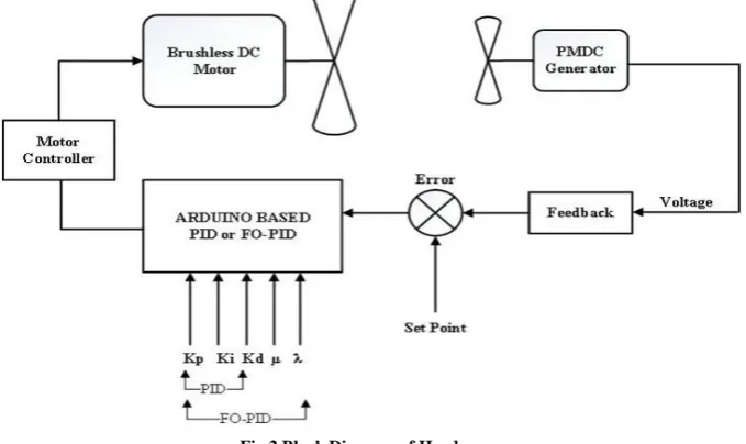
controllers. The control algorithm was provided to the Ardiuno microcontroller via programming based on PID and FOPID algorithms. The hardware incorporates various sections encompassing the Ardiuno microcontroller, brushless DC motor, propeller, electronic speed controller (motor driver), and PMDC generator. The speed of the brushless motor is controlled using the motor driver circuit that receives various input voltage signals based upon the values of the potentiometers. The controller used here is an Atmeg2560 microcontroller embedded in an Ardiuno Mega Mini board. The block diagram of the hardware is shown below in Fig.2.
Fig.2 Block Diagram of Hardware
The controller is programmed with PID and FOPID control algorithms tuned with the optimum parameters for the Kp, Ki
and Kd constants for PID controller and two more controls of µ, and λ for FOPID controller. The laboratory testing model for the
Ardiuno based real time implementation of PMDC generator was developed with PID and FOPID control. The input was provided by the different potentiometers to set the optimum value of process control parameters based on which results were observed and noted. The hardware was tested for various values of PID and FOPID control parameters that were later compared. The Circuit diagram is shown in Fig.3.
IV.HARDWARE DEVELOPMENT &IMPLEMENTATION
The design of hardware is completed by taking various steps. These are explained below.
A. Framework Development
The framework is designed including the shaft on which the motor and PMDC generator are mounted, the base, clamps and hubs for mounting potentiometer for providing the input to the process parameters and other parts required to fix propeller on the motor shaft and circuit on the base. Also, the PMDC generator is fixed on another shaft that is provided with a rotating fan on its shaft. When the high speed brushless motor is powered up, the fan on the generator rotates due to propulsion and hence, the generator produces electricity. The output is received as a feedback from the DC generator and provided to the input of the Ardiuno microcontroller where it calculated and displayed on the serial monitor. Also the values of the parameters adjust accordingly to make the output voltage close to the set point.
B. Implementation of PID & FOPID algorithm by Ardiuno Microcontroller
The PID and FOPID control algorithms are implemented in the Ardiuno microcontroller to control the output voltage of the PMDC generator and keep it close to the set point. The controller is programmed with PID and FOPID control algorithms tuned with the optimum parameters for the Kp, Kv and Ki constants for PID controller
and two more controls of µ, and λ for FOPID controller. Finally, the completed hardware is tested and the results were compared for the PID and FOPID controllers.
C. Interfacing ESC with BLDC Motor
The brushless motor has three wires “A,” “B,” and “C,” at its output and their “free” ends, those that stick out of the motor, are connected to the ESC. The ESC uses electronics to connect any of these wires to positive or negative, to achieve one of six possible combinations that results in an electromagnetic field in a precise location in the motor. With the design and implementation of Ardiuno based PID and FOPID control system for PMDC generator, it has been concluded that as per the different voltages of the input potentiometers, there are different set points that could be adjusted as per different PID and FOPID tuning parameter values, Kp, Ki, Kd, µ, and λ. Both the types of tuning methods could be performed on the designed hardware model. Also, with the help of Ardiuno base serial communication and its supporting software platform, the data could be seen in real-time on a computer related to the output voltages for different set-points for PID and FO-PID Control algorithms.
The hardware was tuned with the different parameters for the PID controller and the FOPID controller. The controller was programmed with PID and FOPID control algorithms tuned with the optimum parameters for the Kp, KI
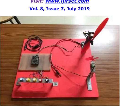
and KD constants for PID controller and two more controls of µ and λ for FOPID controller. The Fig. 4 shows the
Fig. 4 Hardware of PID and FOPID Control System for PMDC Generator
The hardware implementation for the proposed model have been performed using the arrangement of a Brushless motor propeller connected with the Ardiuno mega mini microcontroller and another fan based PMDC generator to generate an output voltage corresponding to the speed of the propeller. The set point of various control parameters is varied with external potentiometers for changing the values of Kp, Ki, Kd, µ, and λ. These parameters were used to tune the PID and FOPID controllers. The control algorithm was provided to the Ardiuno microcontroller via programming based on PID and FOPID algorithms. The hardware incorporates various sections encompassing the Ardiuno microcontroller, brushless DC motor, propeller, electronic speed controller (motor driver), and PMDC generator. The speed of the brushless motor is controlled using the motor driver circuit that receives various input voltage signals based upon the values of the potentiometers. The controller used here is an Atmeg2560 microcontroller embedded in an Ardiuno Mega Mini board.The controller is programmed with PID and FOPID control algorithms tuned with the optimum parameters for the Kp, Ki and Kd constants for PID controller and two more controls of µ, and
λ for FOPID controller. The laboratory testing model for the Ardiuno based real time implementation of PMDC generator was developed with PID and FOPID control. The input was provided by the different potentiometers to set the optimum value of process control parameters based on which results were observed and noted. The hardware was tested for various values of PID and FOPID control parameters that were later compared.
V. RESULTS&DISCUSSIONS
The hardware was tuned with the different parameters for the PID controller and the FOPID controller as well. The controller was programmed with PID and FOPID control algorithms tuned with the optimum parameters for the Kp, Ki
and Kd constants for PID controller and two more controls of µ, and λ for FOPID controller. The PID and FOPID
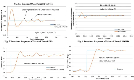
Fig. 5 Transient Response of Manual Tuned PID Fig. 6 Transient Response of Manual Tuned FOPID
Fig. 7 Step Response of Manual Tuned PID controller Fig. 8 Step Response of FOPID after step Input
Fig. 9 Transient Response of PMDC with PID Control Fig. 10 Transient Response of PMDC with FOPID Control
From above results we can compare and analysis the results of both the controller for various parameters. The comparison of PID and FOPID controller at various parameters is tabled below in table 1.
Table 1 Response of PID and FOPID controller for PMDC Generator
Parameters PID FOPID
Rise Time (ms) 280 255
Settling Time(ms) 980 760
Max. Deviation in Output 1.2 1.0
Delay time(ms) 150 136
Peak Time (ms) 270 250
VI.CONCLUSION
From the results obtained by software simulation and hardware implementation of PID and FOPID controller, it can be concluded that the rise time parameters for simple PID controller is 280 milliseconds, which is slightly higher than 250 milliseconds for FOPID controller, settling time which is an important parameter is very less 760 milliseconds for FOPID controller as compared to simple PID Controller having settling time of 980 milliseconds. Also, the response parameters like steady state error and maximum overshoot have been reduced significantly from 0.15 to 0.13, along with improved system performance. Maximum deviation of voltage for FOPID controller is 1 which is very improved as compared to PID which is 1.2. It has also been observed that the parameters µ, and λ, reduced the steady state error and offset in the output of the FOPID controller. For optimal results, the value of the constants should be kept in a range that gives best response output with lesser oscillations at reduced offset.
REFERENCES
[1] J. G. Ziegler and N. B. Nichols, “Optimum Settings for Automatic Controllers,” American Society of Mechanical Engineer, Vol. 6, No. 4, pp.759–768, 2008M. Bertalmio, G. Sapiro, V. Caselles, and C. Ballester, “Image inpainting”, in Proc. SIGGRAPH, pp. 417–424, 2000. [2] L. Yao, Chin-Chin Lin,“ Design of Gain Scheduled Fuzzy PID Controller,” World Academy of Science, Engineering and Technology
International Journal of Electrical and Information Engineering, Vol. 1, No.1, pp. 102-106, 2007.
[3] K .J Astrom, T. Hagglund, “The future of PID control”, Control Engineering Practice, Vol. 9, pp. 1163-1175, 2001. [4] Moasa Ogawa and Tohru Katayama, “A Robust Tuning Method for PID Controller Incorporating a Constraint on Manipulated Variable”,
Trans. of the Society of Instrument and Control Engineers, Vol. E-1, No.1, 265/273, 2001.
[5] Y. Wang , Q. Jin, R. Zhang , “Improved fuzzy PID controller design using predictive functional control structure,” ISA Transactions, pp. 1-10, August, 2017
[6] George K. I. Mann, Bao-Gang Hu, and Raymond G. Gosine,”Analysis of Direct Action Fuzzy PID Controller Structures”, IEEE Transactions on Systems, Man and Cybernetics Part-B: Cybernetic, Vol. 29, No. 3, June 1999.
[7] Iztok Fister Jr., Xin-She Yang, Iztok Fister, Janez Brest, Dusan Fister, “A Brief Review of Nature-Inspired Algorithms for Optimization”, Vol. 80, No. 1-2, pp. 1-7, 2013.
[8] Ramiro S. Barbosa, Isabel S. Jesus, “Comparative Study of Fuzzy Integer and Fractional PID Controller,” 39th Annual Conference of IEEE Industrial Electronics Society, pp. 3390-3395, Austria, 10-13 November, 2013.
[9] Hyo-Sung Ahn, Varsha Bhambhani and Yang Quan Chen, “Fractional-order integral and derivative controller design for temperature profile control” Proceeding of IEEE Chinese Control and Decision Conference, pp. 4766-4771, Yantai, Shandong, China, August 2008.
[10] Shivaji Karad, Dr. S. Chatterji, Prasheel Suryawanshi, “Performance Analysis of Fractional Order PID Controller with the Conventional PID Controller for Bioreactor Control,” International Journal of Scientific and Indian Research, Vol. 3, No. 6, June 2012.
[11] Dominik Sierociuk, Michal Macias, “Comparison of Variable Fractional Order PID Controller for different Types of Variable Order Derivatives,” Proceedings of the 14th
IEEE International Carpathian Control Conference, pp. 334-339, Rytro, Poland, July 2013.