K/J VALUE ESTIMATION OF DIFFERENT SPECIMEN TYPES
CONTAINING DISSIMILAR METAL WELDS
Oliver Martin1, Gangadhar Machina1 and Igor Simonovski1
1 Scientific Officer, European Commission, Joint Research Centre (JRC), Institute for Energy and
Transport (IET), Petten, The Netherlands (email corresponding author: [email protected])
ABSTRACT
The scope of this paper are analytical and numerical J-integral calculations on three standard specimens namely compact tension (CT) specimen, three-point single edge notch bending (3P-SENB) specimen and single edge notch tension (SENT) specimen with two different crack length versus specimen width ratios each. The performed calculations are the first part of a mini round robin exercise within the FP7 project MULTIMETAL, whose main goals are the development of a standard for fracture resistance testing for multi-metallic specimen and the development of harmonized procedures for the integrity assessment of dissimilar metal welds (DMWs) as they appear in primary piping systems of light water reactors (LWRs). Within the round-robin exercise the project partners have to perform numerical J-integral analyses on multi-metalic specimen that are extracted from different mock-ups containing DMWs. In a preliminary step each participating organization has to perform numerical J-integral calculations on fictitious homogeneous specimens, which are assumed to be entirely made of Inconel 52. The numerical results of the preliminary step are compared to analytical solutions taken from literature. The numerical results presented in this paper are the preliminary step results of JRC. For the CT specimens analytical and numerical J-integral solutions are in perfect agreement, where as for the SENB and the SENT specimens analytical and numerical J-integral values only agree for loads up to approximately 60% and 50% respectively of the corresponding limit loads. For higher loads analytical and numerical J-integral values deviate and the deviation reaches around 30% at the limit loads of the two specimens, which requires an in-depth study of the theory behind the analytical solutions for SENB and SENT specimen.
THE MULTIMETAL PROJECT AND SCOPE OF NUMERICAL ANALYSES
The numerical analyses presented in this paper are part of the project MULTIMETAL, which is funded by the European Commission (EC) within its 7th Framework Program (FP7). The main goals of the project are the development of a standard for fracture resistance testing for multi-metallic specimen and the development of harmonized procedures for the integrity assessment of dissimilar metal welds (DMWs) as they appear in primary piping systems of light water reactors (LWRs). The underlying aim of the project is to provide recommendations for a good practice approach for the integrity assessment of DMWs as part of overall integrity analyses and leak-before-break (LBB) procedures.
MULTIMETAL contains an extensive experimental programme involving material characterisation tests and fracture tests. The latter are performed using standard fracture testing specimen as they are defined in ASTM E1820-09 (2011). The specimen are extracted from three different mock-ups, which are thick welded plates each consisting of a plate made of ferritic steel and a plate made of austenitic stainless steel that are joined together via welding. The weld geometry, the materials involved and the applied welding procedure of each mock-up resemble real DMWs as they appear in current LWRs.
single edge notch tension specimen (SENT) and involve different weld geometries and materials, since three different mock-ups are involved, but also different crack locations and crack depths. In a preliminary step each participating organisation had to perform numerical J-value estimations for fictitious homogeneous specimens, consisting of just one material (Inconel 52). Two different crack-depths had to be considered for each of the three specimen involved. The computed J-values are compared with analytical solutions from literature. In this paper the results of the Joint Research Centre (JRC) in Petten, The Netherlands of the preliminary step are presented.
MODEL DESCRIPTION
Two dimensional (2D) plane-strain models are used for the analyses and the models are generated with the pre- and postprocessor ABAQUS/CAE via PHYTON scripts. The FE analyses are performed with the solver ABAQUS/Standard (2011) Version 6.12. For each specimen two different crack length versus width ratios (a/w ratios) are considered, which are displayed in Table 1 together with the main dimensions of the specimens.
Table 1: Main dimensions of all three specimens and chosen a/w ratios
Parameter/Specimen type
CT12.5
3P-SENB20
SENT22
B-thickness [mm]
12.5
20.0
22.0
W-Width [mm]
25.0
20.0
22.0
L-length/H-height [mm]
30.0
90.0
88.0
a/w ratio
0.5
0.75
0.5
0.75
0.3
0.5
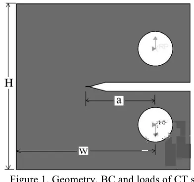
Figure 1 shows the geometry, boundary conditions (BC) and loads of the CT specimen. Figure 2 depicts near tip mesh of the CT specimen, which is generated as a focused mesh. The crack tip is meshed using a ring of collapsed quadric quadrilateral elements and this meshing approach is applied for all three specimens. The singularity for stresses and strains has been implemented using the contour integral crack optional capabilities in ABAQUS. The loading pins are modeled as rigid bodies and the load is applied to the reference points of the rigid bodies.
Figure 1. Geometry, BC and loads of CT specimen Figure 2. Near tip mesh of the CT specimen
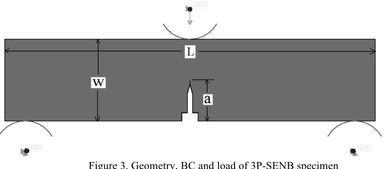
loading pin. Node to surface contact with finite-sliding formulation is defined between the pins and the specimen. Analyses for the SENB specimens are performed in two steps. In the first step contact is established between the pins and specimen by applying a small displacement (2 x 10⁻⁷) in vertical direction. In the second step, which is the actual load step, a force equivalent to limit load is applied onto the reference point of the loading pin.
Figure 3. Geometry, BC and load of 3P-SENB specimen
Figure 4 shows the geometry, boundary conditions and loads of the SENT specimen. The tension load is applied as surface loads at both end surfaces of the specimen and vertical displacements of the bottom corner nodes are suppressed to prevent rigid body motions. Mesh convergence studies have been performed for all three specimens.
Figure 4. Geometry, BC and load of SENT specimen
The specimens are assumed to be made entirely of Inconel 52 and the experimental stress-strain curve has been provided in the form of data points (couples of corresponding true stress and true strain values). Analytical J-Integral calculations like the ones described in Kumar el al. (1981) and Anderson (2005) are typically based on Ramberg-Osgood material models. So in order to facilitate a comparison with analytical J-Integral solutions, Ramberg-Osgood material parameters have been fitted to the provided experimental stress-strain curve for Inconel 52 in the range 0 to 10% strain. Table 2 lists the extracted Ramberg-Osgood parameters and they have been used for all the analytical calculations and FE analyses presented in this paper.
Table 2: Ramberg-Osgood parameters for Inconel 52
Young’s modulus E
Reference (yield) stress σ0
Poisson’s ratio υ
Strain hardening exponent n
Ramberg-Osgood coefficient α
RESULTS
CT Specimen
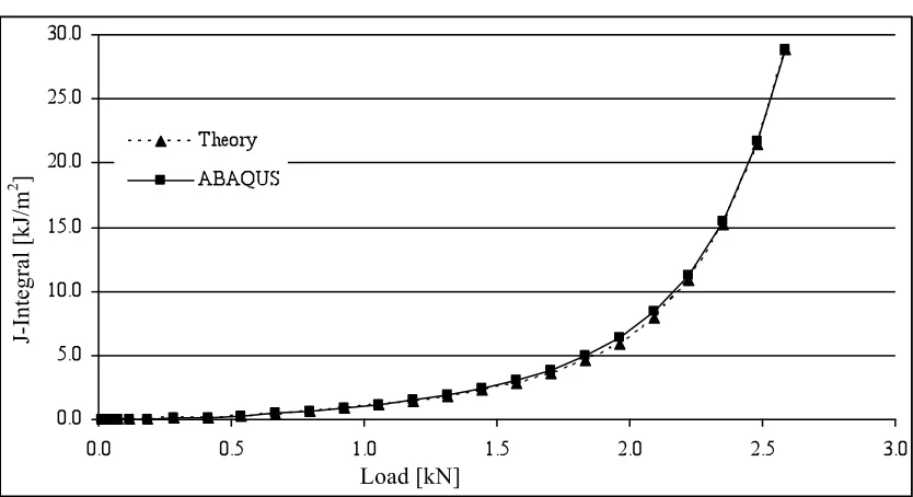
Analytical values for the J-Integral for the two crack length versus width ratios are obtained from the formulas and tables given in Kumar el al. (1981), Anderson (2005) and Tada et al. (2000). Figures 5 and 6 show the analytical and numerical J-integral versus load curves for a/w ratios of 0.5 and 0.75 respectively. For both a/w ratios analytical and numerical solutions are in perfect agreement.
Figure 5. J-Integral vs. load for CT specimen, a/w = 0.5
Figure 6. J-Integral vs. load for CT specimen, a/w = 0.75
J-In
te
gr
al
[
kJ
/m
2 ]
Load [kN]
J-In
te
gr
al
[
kJ
/m
2 ]
3P- SENB Specimen
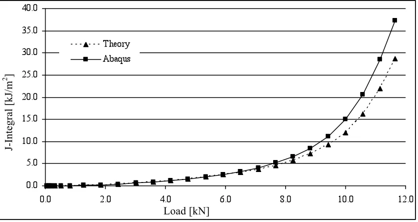
Figures 7 and 8 show the analytical and numerical solutions for the J-integral versus load for the 3P-SENB specimen for a/w ratios of 0.5 and 0.75 respectively. Analytical and numerical solution are in perfect agreement for up to a load of 7.5 kN and 1.75 kN respectively, which corresponds to approximately 60% of the limit load in both cases. Beyond these loads numerical J-integral values rise more significantly with increasing load than the analytical ones. At the limit load itself the numerical J-integral value is approximately 25% and 33% respectively higher than the analytical ones. With higher a/w ratio and rising load the level of triaxiality around the crack tip and in ligament becomes more significant, which we suspect is the cause for the deviations between analytical and numerical J-integral curves.
Figure 7. J-Integral vs. load for 3P-SENB specimen, a/w = 0.5
Figure 8. J-Integral vs. load for 3P-SENB specimen, a/w = 0.75
J-In
te
gr
al
[
kJ
/m
2 ]
Load [kN]
Load [kN]
J-In
te
gr
al
[
kJ
/m
SENT Specimen
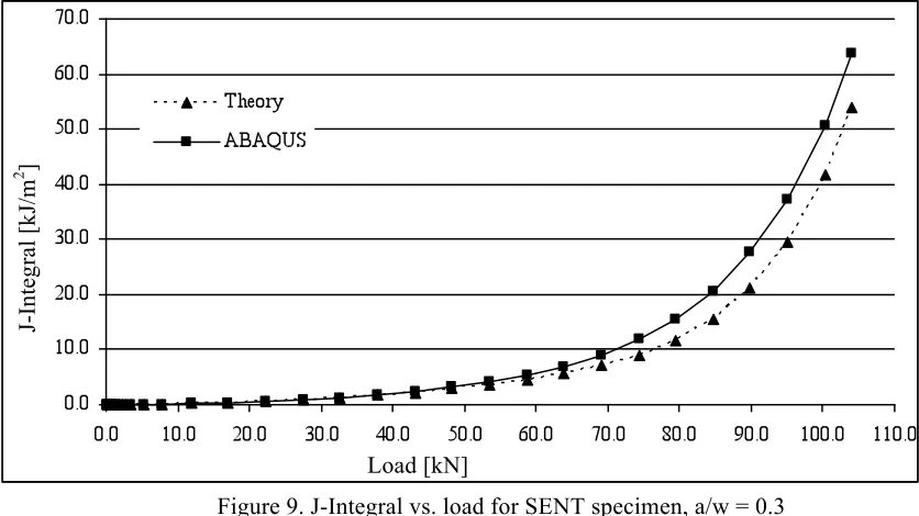
Figures 9 and 10 show the analytical and numerical solutions for the J-integral versus load for the SENT specimen for a/w ratios of 0.3 and 0.5 respectively. For a/w ratio of 0.3 analytical and numerical solution are in perfect agreement for up to a load of 55 kN, which corresponds to approximately 50% of the limit load. Beyond this load numerical J-integral values grow faster than the analytical ones. At the limit load the deviation between both values is approximately 15%. For a/w ratio 0.5 a similar trend can be observed. Until 50% of the limit load analytical and numerical solution are in perfect agreement. With further increasing loads numerical J-integral values rise more significantly than analytical ones, so that at the limit load the difference is approximately 30%. Again we suspect the higher level of triaxilaity around the crack tip and in the ligament for higher a/w ratios and loads to be the reason for the deviation between the two J-integral curves.
Figure 9. J-Integral vs. load for SENT specimen, a/w = 0.3
Figure 10. J-Integral vs. load for SENT specimen, a/w = 0.5
J-In
te
gr
al
[
kJ
/m
2 ]
Load [kN]
J-In
te
gr
al
[
kJ
/m
2 ]
CONCLUSION AND NEXT STEPS
Analytical and numerical J-integral calculations have been performed for three standard specimens namely CT, 3P-SENB and SENT with two different ratios crack length versus specimen width each. The performed calculations are the first part of a mini round-robin exercise within the FP7 project MULTIMETAL, whose main goals are the development of a standard for fracture resistance testing for multi-metallic specimen and the development of harmonized procedures for the integrity assessment DMWs as they appear in primary piping systems of LWRs. Within the round-robin exercise the project partners have to perform numerical J-integral analyses on multi-metalic specimen that are extracted from mock-ups containing DMWs. In a preliminary step each participating organization has to perform numerical J-integral calculations on fictitious homogeneous specimens, which are assumed to be entirely made of Inconel 52. The numerical results of the preliminary step are compared to analytical solutions taken from literature.
The numerical results presented in this paper are the preliminary step results of JRC. For the CT specimen analytical and numerical J-integral solutions are in perfect agreement, where as for the SENB and the SENT specimen analytical and numerical J-integral values only agree for loads up to approximately 60% and 50% respectively of the corresponding limit load. For higher loads analytical and numerical J-integral values deviate and at the corresponding limit load the deviation reaches 33% for the SENB for an a/w ratio of 0.75 and 30% for the SENT specimen for an a/w ratio of 0.5. However, for the lower a/w ratios the deviations between analytical and numerical J-integral values at the corresponding limit load for both specimens are lower, but still significant. The deviations for the SENB and SENT specimens require an in-depth study of the theory behind the analytical solutions for both specimens before proceeding to the next step of the round robin exercise, numerical J-integral value estimations of multi-metalic specimens.
ACKNOWLEDGMENT
The authors would like to thank Stephane Marie and Ms Myriam Bourgeois from the “Commissariat à l’énergie atomique et aux energies alternatives (CEA)” for kindly providing material data for Inconel 52. The authors would also like to thank the European Commission, General Directorate “Research and Innovation” (DG RTD) for funding MULTIMETAL.
REFERENCES
ABAQUS, (2012). “Abaqus Analysis User's Manual”, Dassault Systèmes Simulia Corp., Providence, RI, USA.
Anderson, T. L. (2005). Fracture Mechanics: Fundamentals and Applications, Third Edition, CRC Press, New York.
ASTM E1820-09. (2011). “Standard Test Method for Measurement of Fracture Toughness,” ASTM International, West Conshohocken, PA, USA.
Kumar, V., German, M. D. and Shih, C. F. (1981). “An engineering approach for elastic-plastic fracture analysis,” Report NP-1931, Electric Power Research Institute, Palo Alto, CA, USA.