A Self -Test Approach Based Arithmetic BIST
for Test Pattern Generation
Shaik anjumara
1, P. Bala Murali Krishna
21PG student, Dept of ECE, Sri Mittapalli Institute of Technology for Women, Tummalapalem, Guntur, A.P, India
2Professor, Dept of ECE, Sri Mittapalli Institute of Technology for Women, Tummalapalem, GunturA.P, India
ABSTRACT: The objective of the BIST is to reduce power dissipation without affecting the fault coverage. Weighted pseudorandom built-in self - test (BIST) schemes have been utilized in order to drive down the number of vectors to achieve complete fault coverage in BIST applications. Weighted sets comprising three weights, namely 0, 1, and 0.5 have been successfully utilized so far for test pattern generation, since they result in both low testing time and low consumed power. In this approach, the single input change patterns generated by a counter and a gray code generator are Exclusive–ORed with the seed generated by the low power linear feedback shift register [LP-LFSR]. Since accumulators are commonly found in current VLSI chips, this scheme can be efficiently utilized to drive down the hardware of BIST pattern generation, as well. From the implementation results, it is verified that the testing power for the proposed method is reduced by a significant percentage.
KEYWORDS:Built-in self-test(BIST), VLSI testing, weighted test pattern generation, low power linear feedback shift register [LP-LFSR]
I. INTRODUCTION
Pseudorandom built-in self- test (BIST) generators have been widely utilized to test integrated circuits and systems. The arsenal of pseudorandom generators includes, among others, linear feedback shift registers (LFSRs) [1], cellular automata [2], and accumulators driven by a constant value [3]. For circuits with hard-to-detect faults, a large number of random patterns have to be generated before high fault coverage is achieved. Therefore, weighted pseudorandom techniques have been proposed where inputs are biased by changing the probability of a “0” or a “1” on a given input from 0.5 (for pure pseudorandom tests) to some other value [10], [15].
Weighted random pattern generation methods relying on a single weight assignment usually fail to achieve complete fault coverage using a reasonable number of test patterns since, although the weights are computed to be suitable for most faults, some faults may require long test sequences to be detected with these weight assignments if they do not match their activation and propagation requirements. Multiple weight assignments have been suggested for the case that different faults require different biases of the input combinations applied to the circuit, to ensure that a relatively small number of patterns can detect all faults [4]. Approaches to derive weight assignments forgiven deterministic tests are attractive since they have the potential to allow complete coverage with a significantly smaller number of test patterns [10].
0, 1, and 0.5. From the above we can conclude that 3-weight pattern generation based on weights 0, 1, and 0.5 has practical interest since it combines low implementation cost with low test time.
Current VLSI circuits, e.g., data path architectures, or digital signal processing chips commonly contain arithmetic modules [accumulators or arithmetic logic units (ALUs)]. This has fired the idea of arithmetic BIST (ABIST) [6]. The basic idea of ABIST is to utilize accumulators for built-in testing (compression of the CUT responses, or generation of test patterns) and has been shown to result in low hardware overhead and low impact on the circuit normal operating speed [22]. In [22], Manichet al. presented an accumulator-based test pattern generation scheme that compares favorably to previously proposed schemes. In [7], it was proved that the test vectors generated by an accumulator whose inputs are driven by a constant pattern can have acceptable pseudorandom characteristics, if the input pattern is properly selected. However, modules containing hard-to-detect faults still require extra test hardware either by inserting test points into the mission logic or by storing additional deterministic test patterns. In order to overcome this problem, an accumulator-based weighted pattern generation scheme was proposed in [11]. The scheme generates test patterns having one of three weights, namely 0, 1, and 0.5 therefore it can be utilized to drastically reduce the test application time in accumulator-based test pattern generation. However, the scheme proposed in [11] possesses three major drawbacks: 1) it can be utilized only in the case that the adder of the accumulator is a ripple carry adder; 2) it requires redesigning the accumulator; this modification, apart from being costly, requires redesign of the core of the data-path, a practice that is generally discouraged in current BIST schemes; and 3) it increases delay, since it affects the normal operating speed of the adder.
In this paper, a novel scheme for accumulator-based 3-weight generation is presented. The proposed scheme copes with the inherent drawbacks of the scheme proposed in [11]. More precisely: 1) it does not impose any requirements about the design of the adder (i.e., it can be implemented using any adder design); 2) it does not require any modification of the adder; and hence, 3) does not affect the operating speed of the adder. Furthermore, the proposed scheme compares favorably to the scheme proposed in [11] and [22] in terms of the required hardware overhead. A better low power can be achieved by using single input change pattern generators [17]. It is proposed that the combination of LFSR and scan shift register is used to generate random single input charge sequences. In [12], it is proposed that (2m-1) single input change test vectors can be inserted between two adjustment vectors generated by LFSR, m is length of LFSR. The average and peak power are reduced by using the above techniques. Still, the switching activities will be large when clock frequency is high.
This paper is organized as follows. In Section2, the idea underlying the accumulator-based 3-weight generation is presented. In Section3, the design methodology to generate the 3-weight patterns utilizing an accumulator results are presented. In Section4, the proposed scheme is compared to the previously proposed ones. Finally, Section5 concludes this paper.
II.SYSTEM DESIGN MODE
Accumulator-based 3-weight pattern generation : we shall illustrate the idea of an accumulator-based 3-weight pattern
Table -1:Test Set for the c17 Benchmark
Test Vector Inputs A[4:0] T1
T2 T3 T4
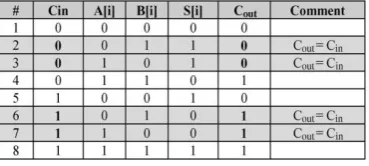
Table -2:Truth Table for Full Adder
generation by means of an example. Let us consider the test set for thec17 ISCAS benchmark [12] given in Table 1. Starting from this deterministic test set, in order to apply the3-weight pattern generation scheme, one of the schemes proposed in [5], [8], and [9] can be utilized. According to these schemes, atypical weight assignment procedure would involve separating the test set into two subsets, S1 and S2 as follows:S1={T1,T4} andS2={T2,T3}. The weight assignments for these subsets is W(S1)={- ,- , 1,- ,1} and W(S2)={-, -, 0, 1, 0}, where a “_” denotes a weight assignment of 0.5, a “1” indicates that the input is constantly driven by the logic “1” value, and “0” indicates that the input is driven by the logic “0” value. In the first assignment, inputs A[2] and A[0] are constantly driven by “1”, while inputs A[4], A[3], A[1] are pseudo randomly generated (i.e., have weights 0.5). Similarly, in the second weight assignment (subset S2), inputs A[2] and A[0] are constantly driven by “0”, input A[1] is driven by “1” and inputs A[4] and A[3] are pseudo randomly generated.
The above reasoning calls for a configuration of the accumulator, where the following conditions are met: 1) an accumulator output can be constantly driven by “1” or “0” and 2) an accumulator cell with its output constantly driven to “1” or “0” allows the carry input of the stage to transfer to its carry output unchanged. This latter condition is required in order to effectively generate pseudorandom patterns in the accumulator outputs whose weight assignment is “_”.
Design methodology : The implementation of the weighted-pattern generation scheme is based on the full adder truth
table, presented in Table 2. From Table 2 we can see that in lines #2, #3, #6, and #7 of the truth table, Cout = Cin. Therefore, in order to transfer the carry input to the carry output, it is enough to set A[i] = NOT (B[i]). The proposed scheme is based on this observation.
Fig -1: Accumulator Cell
signals. In the same figure the respective cell of the driving register B[i] is also shown. For this accumulator cell, one out of three configurations can be utilized, we can configuration that drives the CUT inputs when A[i] = 1 is required. Set[i]=1 and Reset[i] = 0 and hence A[i] = 1 and B[i] = 0. Then the output is equal to 1, and Cin is transferred to C out. And we can configuration that drives the CUT inputs when A[i]= 0 is required. Set[i] = 0 and Reset[i] = 1 and hence A[i] = 0 and B[i] = 1. Then, the output is equal to 0 and C in is transferred to Cout. And finally we can configuration that drives the CUT inputs when A[i] = “_” is required. Set[i] = 0 and Reset[i] = 0.
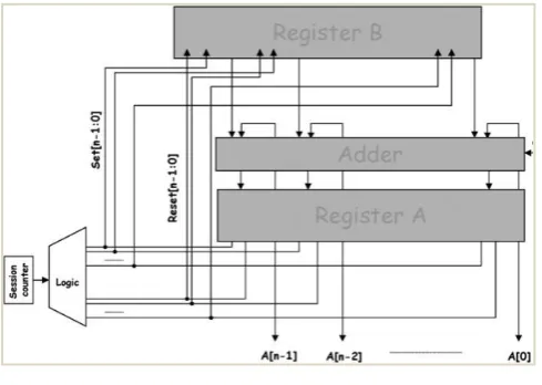
Fig -2: Proposed Scheme
The D input of the flip-flop of register B is driven by either 1 or 0, depending on the value that will be added to the accumulator inputs in order to generate satisfactorily random patterns[16] to the inputs of the CUT. In Fig. 2, the general configuration of the proposed scheme is presented. The Logic module provides the Set[n-1:0] and Reset[n-1:0] signals that drive the S and R inputs of the Register A and Register B inputs. Note that the signals that drive the S inputs of the flip-flops of Register A, also drive the R inputs of the flip-flops of Register B and vice versa.
Fig -3: BIST Approach
BIST Approach : BIST is a design for testability (DFT) technique in which testing is carried out using built –in
hardware features. Since testing is built into the hardware, it is faster and efficient. The BIST architecture shown in fig.4 needs three additional hardware blocks such as a pattern generator, a response analyzer and a test controller to a digital circuit. For pattern generators, we can use either a ROM [14] with stored patterns, or a counter or a linear feedback shift register (LFSR). A response analyzer is a compactor with stored responses or an LFSR used as a signature analyzer. A controller [18] provides a control signal to activate all the blocks. BIST has some major drawbacks where architecture is based on the linear feedback shift register [LFSR][19]. The circuit introduces more switching activities in the circuit under test (CUT)during test than that during normal operation. It causes excessive power dissipation and results in delay penalty into the design.
Test Pattern Generation
Test Controller
Output Response Analyzer(O RA) Circuit Under
Test(CUT)
Input Isolatory Circuitary
BIST Start BIST Done
System Inputs
Pass/Fail
III.SIMULATION RESULTS
The proposed system is implemented by using Xilinx Software and the simulation waveforms of each module are shown below.
Accumulator Cell: The simulation result of cell is shown in figure4. When Set[i]=1 and Reset[i]=0 and hence A[i]=1
and B[i]=1.Then, output is equal to 1, and Cin is transferred to Cout. The logic module of Accumulator cell provides
Set[n-1:0] and Reset[n-1:0] signals that drive the S and R inputs of the Register A and Register B. Note that the signals that drive the S inputs of the flip flops of Register A, also drive the R inputs of Register B and vice versa.
Fig -4: Accumulator Cell
Linear Feed Back Shift Register: In the 3-weight pattern generation scheme the scan chain for session counter is
driven by the output of linear feedback shift register (LFSR) [1]. the result is shown in figure 5. Logic is inserted between the scan chain and the CUT inputs to fix the outputs to the required weight (0, 0.5, 1).For the scan chain of session counter the number of LFSR stages is (log2n) where n is the number of scan cells.
Top Module: The D input of the flip-flop of register B is driven by either 1 or 0, depending on the value that will be added to the accumulator inputs in order to generate satisfactorily random patterns to the inputs of the CUT.As per the LFSR out to session counter count the Cin from the Registers transferred as the Cout to generate test vectors for weight
patterns. the result is shown in below figure 6.
Fig -6: Top Module
IV.COMPARISIONS
In this section we are comparing the proposed scheme with the existing systems. Table3 shows the hardware overhead and delay from Cin to Cout of proposed system compared with existing system. Table4 shows the no. of LFSRs and scan counters in proposed systems with the existing systems.
In table3, we compare the proposed scheme with the accumulator-based 3-weight generation scheme proposed
in [11]. In Section4, we compare the proposed scheme with the 3-weight scan schemes proposed in [5] and [8].
In the 3-weight pattern generation scheme proposed by Pomeranz and Reddy in [5] the scan chain is driven by the output of a linear feed-back shift register (LFSR). Serial fixing scheme is shown to be more costly [8]; therefore we shall concentrate our comparisons to the parallel fixing BIST scheme.
Table -4: Comparisons with the Scan Scheme Proposed in [5] and [8]
The below table5 is the device utilization summary in the synthesis report after completion of simulation process.
Table -5: Design Utilization Summary
V.CONCLUSION
We have presented an accumulator-based 3-weight (0, 0.5, and 1) test-per-clock generation scheme, which can be utilized to efficiently generate weighted patterns without altering the structure of the adder. The seed generated from (LP-LFSR) [20] is Ex-ORed with the single input changing sequences generated from gray code generator, which effectively reduces the switching activities among the test patterns. Thus the proposed method significantly reduces the power consumption during testing mode with minimum number of switching activities using LP-LFSR in place of conventional LFSR in the circuit used for test pattern generator. From the implementation results, it is verified that the proposed method gives better power reduction compared to the exiting method.
REFERENCES
[1] P. Bardell, W. McAnney, and J. Savir, Built-In Test For VLSI: Pseudorandom Techniques. New York: Wiley, 1987.
[2] P. Hortensius, R. McLeod, W. Pries, M. Miller, and H. Card, “Cellular automata-based pseudorandom generators for built-in self test,” IEEE Trans. Comput.-Aided Des.Integr. Circuits Syst., vol. 8, no. 8, pp. 842–859, Aug. 1989.
[3] A. Stroele, “A self testapproach using accumulators as test pattern generators,” in Proc. Int. Symp. Circuits Syst., 1995, pp. 2120–2123. [4] H. J. Wunderlich, “Multiple distributions for biased random test patterns,” in Proc. IEEE Int. Test Conf., 1988, pp. 236–244.
[5] I. Pomeranz and S. M. Reddy, “3 weight pseudo-random test generation based on a deterministic test set for combinational and sequential circuits,” IEEE Trans. Comput.-Aided Des. Integr. Circuits Syst., vol. 12, no. 7, pp. 1050–1058, Jul. 1993.
[6] K. Radecka, J. Rajski, and J. Tyszer, “Arithmetic built-in self-test for DSP cores,” IEEE Trans. Comput.-Aided Des.Integr. Circuits Syst., vol. 16, no. 11, pp. 1358–1369, Nov. 1997.
[7] J. Rajski and J. Tyszer, Arithmetic Built-In Self Test For Embedded Systems. Upper Saddle River, NJ: Prentice Hall PTR, 1998. [8] S. Wang, “Low hardware overhead scan based 3-weight weighted random BIST,” in Proc. IEEE Int. Test Conf., 2001, pp. 868–877.
Logic Utilization Used Available Utilization No.of Slice
Flip-Flops
15 1536 1%
No.of 4 input LUTs
19 1536 1%
No.of Bounded IOBs
9 124 7%
No.of GCLKs 1 8 12% Total equivalent
gate count
[9] S. Zhang, S. C. Seth, and B. B. Bhattacharya, “Efficient test compaction for pseudo-random testing,” in Proc. 14th Asian Test Symp., 2005, pp. 337–342.
[10] J. Savir, “Distributed generation of weighted random patterns,” IEEE Trans. Comput., vol. 48, no. 12, pp. 1364–1368, Dec. 1999.
[11] I. Voyiatzis, D. Gizopoulos, and A. Paschalis, “Accumulator-based weighted pattern generation,” presented at the IEEE Int. Line Test Symp., Saint Raphael, French Riviera, France, Jul. 2005.
[12] R.H.He,X.W.Li and Y.Z.Gong,” A scheme for low power BIST test pattern generator,” micro electronics& computer,no.2,pp.36-39 Feb.2003. [13] S. Wang, “Low hardware overhead scan based 3-weight weighted random BIST architectures,” U.S. Patent 6 886 124, Apr. 26, 2005. [14] C. Hamacher, Z. Vranesic, and S. Zaky, Computer Organization. New York: McGraw Hill, 2002.
[15] F. Brglez, C. Gloster, and G. Kedem, “Hardware-based weighted random pattern generation for boundary scan,” in Proc. IEEE Int. Test Conf. (ITC), 1989, pp. 264–274.
[16] H.-J. Wunderlich, “Self test using unequiprobable random patterns,” in Proc. 17th Int. Symp.Fault-Tolerant Comput. (FTCS), 1987, pp. 258– 263.
[17] O. Novák, Z. Pløva, J. Nosek, A. Hlawiczka, T. Garbolino, and K. Gucwa, “Test-per-clock logic BIST with semi-deterministic test patterns and zero-aliasing compactor,” J. Electron. Testing: Theor. Appl., vol. 20, no. 1, pp. 109–122, Feb. 2004.
[18] Y. Son, J. Chong, and G. Russell, “E-BIST: Enhanced test-per-clock BIST architecture,” IEE Proc.—Comput. Digit.Techn., vol. 149, pp. 9–15, Jan 2002.
[19] K. Yamaguchi, M. Inoue, and H. Fujiwara, “Hierarchical BIST: Testper- clock BIST with low overhead,” Electron. Commun. Japan (Part II: Electron.), vol. 90, no. 6, pp. 47–58, Jun. 2007.
[20] E. Kalligeros, X. Kavousianos, D. Bakalis, and D. Nikolos, “An efficient seeds selection method FOR lfsr-based test-per-clock BIST,” in Proc. Int. Symp. Quality Electron.Des., 2002, p. 261.
[21] A. D. Singh, M. Seuring, M. Gossel, and E. S. Sogomonyan, “Multimode scan: Test per clock BIST for IP cores,” ACM Trans. Design Autom. Electr. Syst., vol. 8, no. 4, pp. 491–505, Oct. 2003.
[22] S. Manich, L. Garcia-Deiros, and J. Figueras, “Minimizing test time in arithmetic test-pattern generators with constrained memory resources,” IEEE Trans. Comput.-Aided Des.Integr. Circuits Syst., vol. 26, no. 11, pp. 2046–2058, Nov. 2007.


![Table -3: Comparison with [11]](https://thumb-us.123doks.com/thumbv2/123dok_us/1475175.1180622/6.595.190.408.232.456/table-comparison-with.webp)
![Table -4: Comparisons with the Scan Scheme Proposed in [5] and [8]](https://thumb-us.123doks.com/thumbv2/123dok_us/1475175.1180622/7.595.188.408.380.521/table-comparisons-scan-scheme-proposed.webp)
