ISSN(Online): 2320-9801
ISSN (Print): 2320-9798
I
nternational
J
ournal of
I
nnovative
R
esearch in
C
omputer
and
C
ommunication
E
ngineering
(An ISO 3297: 2007 Certified Organization)
Vol. 3, Issue 6, June 2015
Performance Analysis of Convolutional Codes
with Bit Error Rate V/S SNR over Channel for
Viterbi Algorithm
Gaurav Vijay, R.P Gupta
Research Scholar, Department of ECE, Career Point University, Kota, India
Principal and Professor, Department of ECE, Manda Institute of Technology, Bikaner, India
ABSTRACT: In a general communication system, the source generates data bits or messages that must be transmitted to a distant user over a noisy channel, and hence errors are made in conveying the source information to the user. A natural objective of any system is to achieve error free transmission in the most economic manner. There are various methods of coding signal that permit to detect errors and to correct errors caused by noise. Coding allows in principle to design a communication system in which both, information bit rate and error rate are independently and arbitrarily specified but subject to a constraint on bandwidth. The usual measure of performance of a coded system is the average error rate that is achieved at specified signal-to–noise ratio.
For Convolutional codes, one important decoding techniques are rigorously used in various communication systems all around. Viterbi decoding is a dominant decoding technique for convolutional codes, have advantages like highly satisfactory bit error rate performance, high speed of operation, ease of implementation, low cost. Results of simulation of sequential decoding and Viterbi decoding for various constraint lengths, SNRs and different decoder delays are given in the chapter results & conclusion.
I. INTRODUCTION
In the recent years, there has been an increasing demand for efficient and reliable digital data transmission and storage system. This demand has been accelerated by the emergence of the large-scale, high speed data networks for the exchange, processing and storage of digital information in the Military, Government, and Private spheres. A merger (i.e. combination) of Communication and computer technology is required in the design of these systems. A major concern of the designer is the control of errors so that reliable reproduction of data can be obtained.
The task facing the designer of a digital communication system is that of providing a cost effective facility for transmitting information from one end of a system at a rate and a level of reliability & quality that are acceptable to the user at the another end. The two, key system parameters, available to the designer are transmitted signal power and channel bandwidth. These two parameters, together with the power spectral density of receiver noise, determine the signal energy per bit-to-noise power spectral density ratio Eb/No. For a fixed Eb/No, the only practical option available for changing data quality to acceptable level is to use Error Control Coding. For a fixed modulation scheme, the addition of redundancy in the coded messages implies the need for increased transmission bandwidth. Moreover, the uses of error control coding add complexity to the system, especially for the implementation of decoding operations at the receiver. Thus the design tradeoffs in the use of error control coding to achieve acceptable error performance includes considerations of bandwidth and system complexity.
ISSN(Online): 2320-9801
ISSN (Print): 2320-9798
I
nternational
J
ournal of
I
nnovative
R
esearch in
C
omputer
and
C
ommunication
E
ngineering
(An ISO 3297: 2007 Certified Organization)
Vol. 3, Issue 6, June 2015
term “memory-less” indicates that each n–symbol block depends only upon a specific k-symbol block and no other. The encoder for the convolutional code is a device with memory that accepts binary symbols in set of mand output binary symbols in set of k. Each set of n output symbols are determined by the current input set and a span of the preceding input symbols.
The effect of errors occurring during transmission is reduced by adding redundancy to the data, prior to transmission in a controlled manner. The redundancy is used to enable a decoder in the receiver to detect and correct errors.The Binary Symmetric Channel (BSC) is completely described by the transition probability p. The majority of coded digital communication systems employ binary coding with hard decision decoding. But its use prior to decoding causes an irreversible loss of information in the receiver. To reduce this loss, Soft decision decoding is used.
The usual measure of performance of a coded system is the average error rate that is achieved at a specified Signal to Noise ratio. The usual method of determining the coding gain (the amount of improvement that is achieved when a particular coding scheme is used) is to plot the probability of errors versus Eb/No for both coded and un coded operations and to read the difference in required Eb/No at a specified error rate.
Convolution coding with hard and soft decision “Viterbi Decoding” has found application in many space and satellite communication system. The different aspects of Decoders are Decoder Delay and Decoding Techniques. By using different decoding algorithms we have made plots between Probabilities of Bit Error Rate (Pe) v/s Signal to Noise Ratio (SNR).
Binary I/P from
Source Binary decoded data
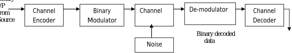
Fig 1: Block Diagram of a Digital Communication System.
II. RELATED WORK
In 2011 A 15.8 pJ/bit/iter Quasi-Cyclic LDPC Decoder for IEEE 802.11n in 90 nm CMOS This paper present a low-power quasi-cyclic (QC) low density parity check (LDPC) decoder that meets the throughput requirements of the highest-rate (600 Mbps) modes of the IEEE 802.11n WLAN standard. The design is based on the layered offset-min-sum algorithm and is runtime-programmable to process different code matrices (including all rates and block lengths specified by IEEE 802.11n.In 2012 Shortening design time through multiplatform simulations with a portable Open CL golden-model: the LDPC decoder case. Here Hardware designers and engineers typically need to explore a multi-parametric design space in order to find the best configuration for their designs using simulations that can take weeks to months to complete.In June-2013 Alexios Balatsoukas-Stimming analyze performance of quantized min-sum decoding of low-density parity-check codes under unreliable message storage. This paper shows the a simple bit-level error model and decoder symmetry is preserved under this model. Subsequently, the formulization corresponding density evolution equations to predict the average bit error probability in the limit of infinite block length. Also present numerical threshold results and shows that using more quantization bits is not always beneficial in the context of faulty decoders. In 2004 LDPC versus Convolutional Codes for 802.11n Application in January by Aleksandar Purkovic, Nina Burns, Sergey Sukobok, Levent Demirekler shows LDPC codes offer considerable performance advantages over the existing convolutional codes. With the proper design LDPC codes can be made flexible enough to satisfy demands of 802.11n applications.Nortel Networks In 2011 Windowed Decoding of Protograph-based LDPC Convolutional Codes over Erasure Chanels: Here consider a windowed decoding scheme for LDPC convolutional codes that is based on the belief-propagation (BP) algorithm. In this advantages of this decoding scheme and identify certain characteristics of LDPC convolution code ensembles that exhibit good performance with the windowed decoder. We
Binary Modulator
Channel Decoder Channel
Channel Encoder
De-modulator
ISSN(Online): 2320-9801
ISSN (Print): 2320-9798
I
nternational
J
ournal of
I
nnovative
R
esearch in
C
omputer
and
C
ommunication
E
ngineering
(An ISO 3297: 2007 Certified Organization)
Vol. 3, Issue 6, June 2015
will consider the performance of these ensembles and codes over erasure channels with and without memory and then show that the structure of LDPC convolution code ensembles is suitable to obtain performance close to the theoretical limits over the memory less erasure channel, both for the BP decoder and windowed decoding.
III. BINARY PHASE SHIFT KEYING (BPSK)
In Binary phase shift keying (BPSK) the transmitted signal is a sinusoidal waveform of fixed amplitude. It has one fixed phase when the data is of one level and when data is at other level, phase difference is 180o .If the sinusoidal waveform is of amplitude A it has power Ps=1/2A2 so that A=√2Ps
Thus the transmitted signal is either
VBPSK(t)= √2 Cos (ωot) (1.1) VBPSK(t)= √2 Cos (ωot +π)
= -√2 Cos (ωot) (1.2)
In BPSK the data b(t) is a stream of binary digit with voltage levels which, we take it +1V and –1V.When b(t)=1V logic level is 1 , When b(t)=-1V logic level is 0.Hence VBPSK(t) can be written as
VBPSK(t)=b(t)* √2 Cos (ωot)
A. Error Control For Data Communication
In digital communication system, error detection and error correction is important for reliable communication. Error detection techniques are much simpler than forward error correction (FEC). But error detection techniques have certain disadvantages. Error detection pre supposes the existence of an automatic repeat request (ARQ) feature which provides for the retransmission of those blocks, segments or packets in which errors have been detected. This assumes some protocol for reserving time for the retransmission of such erroneous blocks and for reinserting the corrected version in proper sequence. It also assumes sufficient overall delay and corresponding buffering that will permit such reinsertion. The latter becomes particularly difficult in synchronous satellite communication where the transmission delay in each direction is already a quarter second. A further drawback of error detection with ARQ is its inefficiency at or near the system noise threshold. For, as the error rate approaches the packet length, the majority of blocks will contain detected errors and hence require retransmission, even several times, reducing the throughput drastically. In such cases, forward error correction, in addition to error detection with ARQ, may considerably improve throughput. Forward error correction may be desirable in place of, or in addition to, error detection for any of the following reasons:
(1) When a reverse channel is not available or the delay with ARQ would be excessive. (2) The retransmission strategy is not conveniently implemented.
B. Channel Coding
It is known that noise-immunity is one of the basic attributes of information transmission systems. Since errors are possible in communication channels during the data transmissions we must apply error-correcting codes to combat these errors [1]. The purpose of forward error correction (FEC) is to improve the capacity of channel by adding some carefully designed redundant information to the data being transmitted through the channel. The process of adding this redundant information is known as channel coding. The various building blocks of digital communication system are channel encoder, binary modulator, channel, demodulator, detector and channel decoder as mentioned in figure 1
C. Block Codes:
Early attempts at designing error control techniques were based on block codes. For every block of k information bits,
ISSN(Online): 2320-9801
ISSN (Print): 2320-9798
I
nternational
J
ournal of
I
nnovative
R
esearch in
C
omputer
and
C
ommunication
E
ngineering
(An ISO 3297: 2007 Certified Organization)
Vol. 3, Issue 6, June 2015
convolution of the input data and the filter impulse response. In almost every application, convolutional codes outperform block codes for the same implementation complexity of the encoder-decoder [4].
IV. CONVOLUTIONAL CODING
The basic objective of the channel coding is to increase the resistance of the digital communication system to channel noise. Convolution code is basically a finite state machine. Convolutional codes are widely used to encode digital data before transmission through noisy or error prone channels. During encoding, k input bits are mapped to n output bits to give rate k/n coded bit stream. The encoder consists of a shift register of K stages, where K is described as the Constraint length of the code.
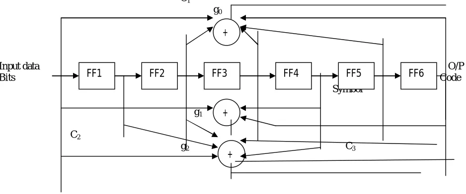
Convolutional encoder plays an important role in the development of modulation schemes for wireless systems. Convolutional codes add a structured redundancy to the information source that mitigates the effect of the random noise corrupting the data stream. Convolutional codes perform better in the marginal regions of Bit Error Rates {10^ (-2) - 10^ (-4)} than block codes such as Reed-Solomon. Since voice communication systems performs satisfactory in this range and are often designed for those Bit Error Rates. Convolutional codes are a common element in wireless systems. Convolutional codes gain their name from the fact that the information source is mathematically convolved with the impulse response of the code. This impulse response is defined by generator function for a particular code. There is a generator function for every output of a Convolutional encoder. These Convolutional Encoders are physically constructed by using shift registers with taps determined by the generator functions as shown in the figure 2. The rate of the encoder is defined as the ratio of inputs to the outputs. The number of taps on the shift register determines how many of the output bits are influenced by the input bits. The number of influenced output bits is called the Constraint Length. To avoid confusion, in practice the constraint length of an encoder is usually taken to the number of memory
elements in the shift register plus one.
C1 g0
Input data O/P
Bits Code
Symbol
g1
C2
g2 C3
Fig 2: Convolutional Encoder
Convolutional codes can be used when bandwidth is more constrained, and allow for a more modest expansion of bit rate from input to output.
We give an example below, where there are two output bits for each input bit. Such a code is said to have a rate ½. More generally, such codes can produce m-tuple of output bits for each k-tuple of input bits but arbitrary integers k<m. These are said to have rate k/m.There is another difference between a convolutional code and a discrete time filter, the inputs and outputs for a convolutional code are binary and the addition is modulo-2.
FF1 FF2 FF3 FF4 FF5 FF6
+
ISSN(Online): 2320-9801
ISSN (Print): 2320-9798
I
nternational
J
ournal of
I
nnovative
R
esearch in
C
omputer
and
C
ommunication
E
ngineering
(An ISO 3297: 2007 Certified Organization)
Vol. 3, Issue 6, June 2015
0C1 Coded output
Digital I/P 0C2
Fig 3: Convolutional Encoder with 3 shift registers A. Code Generation
A Convolutional code is generated by combining the output of k- shift registers through employment of EXCLUSIVE-OR logic summers. Such an Encoder is illustrated in fig3. For the case k=3 and v=2, here M1 through M3 are 1-bit storage devices such as flip-flops. The output v1 and v2 of adder are
v1=s1s2s3 v2=s1s3
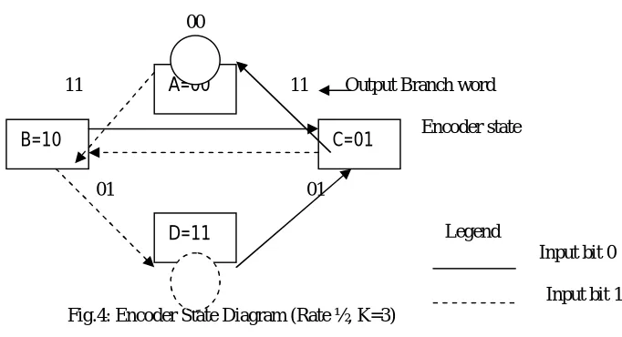
Thus the number of code bits is v times the number of message bits, v being the number of commutator segments. Accordingly, also the rate of code is 1/v.If number of bits in the message stream is L, the number of bits in output code is v(L+K). Generally L is large number while K is relatively small. Hence
v(L+K)vL.
00
11 11 Output Branch word
00
Encoder state
10
01 01
Legend
Input bit 0
10
Input bit 1 Fig.4: Encoder State Diagram (Rate ½, K=3)
V. DECODING ALGORITHS FOR CONVOLUTIONAL CODES
The Decoding of the convolution code can be done by various decoding techniques; Viterbi algorithm is one of the practical techniques. In the absence of noise, the code word will be received as transmitted, hence simple to reconstruct the original message. The maximum likelihood decoding technique was given by Forney, he was the first to point out that the Viterbi algorithm can be used to produce the maximum likelihood estimate of the transmitted sequence over a band-limited channel with inter-symbol interference
A. The Veterbi Algorithm
The equivalence between maximum likelihood decoding and minimum distance decoding for a binary symmetric channel implies that a convolutional code may be decoded by choosing a path in the code tree whose coded sequence differs from the received in the fewest number of places. Since a code tree is equivalent to a trellis, trellis representation
M1 M2 M3
D=11 A=00
ISSN(Online): 2320-9801
ISSN (Print): 2320-9798
I
nternational
J
ournal of
I
nnovative
R
esearch in
C
omputer
and
C
ommunication
E
ngineering
(An ISO 3297: 2007 Certified Organization)
Vol. 3, Issue 6, June 2015
is considered. the reason for preferring the trellis over the tree is that the number of nodes at any level of the trellis does not continue to grow as the number of increasing message bit increases; rather, it remains constant at 2K-1, where K is the constraint length of the code.
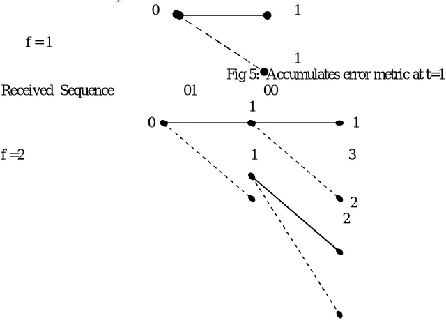
B. Performing Viterbi Decoding
The Viterbi decoder itself is the primary focus of this tutorial. Perhaps the single most important concept to aid in understanding the Viterbi algorithm is the trellis diagram. Trellis diagram for our example rate 1/2 K=3 convolutional encoder, for a 15 bit message.The four possible states of the encoder are depicted as four rows of horizontal dots. There is one column of four dots for the initial state of the encoder and one for each time instant during the message. For a 15 bit message with two encoder memory flushing bits, there are 17 time instants in addition to t=0,which represent the initial condition of the encoder. The solid lines connecting dots in the diagram represent state transitions when the input bit is zero. The states of the trellis that are actually reached during the encoding of our example 15 bit message.The encoder input bits and output symbols are shown in the diagram. The two-bit numbers labeling the lines are the corresponding convolutional encoder channel symbol outputs. The dotted lines represent cases where the encoder input is a zero, and solid lines represent cases where the encoder input is a one. (The two bit binary numbers labeling dotted lines are on the left, and the two bit binary numbers labeling solid lines are in the right.)
Received Sequence 01
0 1
f = 1
1
Fig 5: Accumulates error metric at t=1 Received Sequence 01 00
1
0 1
f =2 1 3
2 2
Fig 6: Accumulates error metric at t=2
ISSN(Online): 2320-9801
ISSN (Print): 2320-9798
I
nternational
J
ournal of
I
nnovative
R
esearch in
C
omputer
and
C
ommunication
E
ngineering
(An ISO 3297: 2007 Certified Organization)
Vol. 3, Issue 6, June 2015
VI. SIMULATION AND RESULT OF VITERBI ALGORITHM
A Veterbi algorithm for decoding the convolutional codes of fixed code rate, fixed constraint length. While going from rate-1/2 convolutional codes, improvement in performance of Veterbi decoding algorithm, for all constraint lengths considered as shown in figures 7 to 10.These figure performance shows how the viterbi algorithm work with constraint lengths.
Fig7. Performance of Viterbi Decoder R=1/2, K=3 Convolution Code=2K Soft Decision
Specification Viterbi Decoding Result
Constraint Length K=3 Rate=1/2 Decoding=2K
BER= 10-1approx SNR=7.89dB for 10000bits
Performance of SNR for same BER 10-1 is 7.48dB gain hence from figure it is
illustrated that the veterbi decoder is much better performance except to other
ISSN(Online): 2320-9801
ISSN (Print): 2320-9798
I
nternational
J
ournal of
I
nnovative
R
esearch in
C
omputer
and
C
ommunication
E
ngineering
(An ISO 3297: 2007 Certified Organization)
Vol. 3, Issue 6, June 2015
Specification Viterbi Decoding Result
Constraint Length K=3 Rate=1/2 Decoding=3K
BER= 10-1approx SNR=4.67dB for 10000bits
Performance of SNR for same BER 10-1 is 4.67dB gain hence from figure
it is illustrated that the veterbi decoder is much better performance
except to other
Fig9. Performance of Viterbi Decoder R=1/2, K=3 Convolution Code HardDecision
Specification Viterbi Decoding Result
Constraint Length K=3 Rate=1/2 Decoding=2K
BER= 10-1approx SNR=1.34dB for 10000bits
Hard Decision Decoding
Performance of SNR for same BER 10-1 is 1.34dB gain hence from figure it is
illustrated that the veterbi decoder is much better performance except to other
Fig10. Performance of Viterbi Decoder R=1/2, K=3 Convolution Code Hard Decision
- 1 0 - 8 - 6 - 4 - 2 0 2 4 6 8 1 0
1 0- 2 1 0- 1 1 00
E b / N o ( d B )
B
E
R
P e r f o r m a n c e o f V i t e r b i d e c o d e r R = 1 / 2 , K = 3 C o n v . C o d e H a r d D e c i s i o n
- 1 0 - 8 - 6 - 4 - 2 0 2 4 6 8 1 0
1 0- 2
1 0- 1
1 00
E b / N o ( d B )
B
E
R
ISSN(Online): 2320-9801
ISSN (Print): 2320-9798
I
nternational
J
ournal of
I
nnovative
R
esearch in
C
omputer
and
C
ommunication
E
ngineering
(An ISO 3297: 2007 Certified Organization)
Vol. 3, Issue 6, June 2015
Specification Viterbi Decoding Result
Constraint Length K=3 Rate=1/2 Decoding=2K
BER= 10-1approx SNR=-1.34dB for 10000bits
Hard Decision Decoding
Performance of SNR for same BER 10-1 is -1.34dB gain hence from figure it is illustrated that the veterbi
decoder is much better performance except to other
VII. CONCLUSION
To conclude my Paper, the forward error correction technique (FEC) is a technique, particularly suited for decoding of convolutional codes with Viterbi Decoding in AWGN channel. A Viterbi Decoding Algorithm can show the bit error rate performance of decoding Algorithm for Soft and Hard Decision decoding Algorithm.The encoding process was demonstrated using a (2,1,3) convolutional encoder. A 3-bit input stream was encoded as an example to show the working of this encoder. A decoding process was shown using a Hard Decision Viterbi Decoding and a Soft Decision Viterbi Decoder. Performance factors affecting the FEC technique was mentioned. These included the encoder memory size and move significant factor of SNR. Viterbi algorithm had a significant impact on our understanding of certain problems, notably in the theories of convolutional codes and of Intersymbol interference.
REFERENCES
1. K. Sh. Zigangirov, “Some sequential decoding procedures,” Probl. Pered. Inform., vol. 2, no. 4, pp. 13-15, 1966.
2. A. J. Viterbi, “Error bounds for convolutional codes and an asymptotically optimal decoding algorithm”, IEEE Trans. Inform. Theory 13,
pp-260–269, April 1967.
3. G. D. Forney, Jr., “Convolutional codes I: Algebraic structure”, IEEE Trans. Inform. Theory 16(6), pp-720–738 ,Nov. 1970.
4. J. A. Heller and I. M. Jacobs. “Viterbi decoding for satellite and space communication”. IEEE Transactions on Communications Technology,
pp-835–848, October 1971.
5. J. A. Heller and I. M. Jacobs, “Viterbi Decoding for Satellite and Space Communications”," IEEE Transactions on Communication Technology,
vol. COM-19, pp. 835-848, October, 1971.
6. J. Clavier, M. Niquil, G. Coffinet, F.Behr, “Théorie et technique de la transmission de des données”, Tome1, Masson, Paris édition, 1972.
7. G. D. Forney, Jr., “The Viterbi algorithm, Proce”. IEEE 61: 268–278, March 1973.
8. L. R. Bahl, J. Cocke, F. Jelinek, and J. Raviv, “Optimal decoding of linear codes for minimizing symbol error rate”, IEEE Trans. Inform. Theory 20(2): 248–287, March 1974.
9. Irwin M. Jacobs “Practical Applications of Coding”. IEEE. pp 305-310, 1974.
10. T. Aulin, N. Rydbeck and C. –E. W. Sundberg, “Continuous Phase Modulation – Part II: Partial response signaling”, IEEE Trans. Commun.,