ISSN (Online) : 2319 - 8753
ISSN (Print) : 2347 - 6710
I
nternationalJ
ournal ofI
nnovativeR
esearch inS
cience,E
ngineering andT
echnologyAn ISO 3297: 2007 Certified Organization, Volume 2, Special Issue 1, December 2013
Proceedings of International Conference on Energy and Environment-2013 (ICEE 2013)
On 12th to 14th December Organized by
Department of Civil Engineering and Mechanical Engineering of Rajiv Gandhi Institute of Technology, Kottayam, Kerala, India
ANALYSIS OF PRECAST MULTISTOREYED
BUILDING
–
A CASE STUDY
Bindurani.P, A. Meher Prasad, Amlan K. Sengupta
Assistant Professor, Dept. of Civil Engineering RIT, Kottayam, Kerala, India
Professor, Dept. of Civil Engineering IIT Madras, India
Associate Professor, Dept. of Civil Engineering IITMadras, India
ABSTRACT
Precast concrete systems represent an efficient alternative for building construction. The behaviour of a precast system depends on connections and it should be modelled properly in the computational models for analysis and design. This study presents the modelling of connections in a wall type precast building system. A case study on a 23-storeyed building, made up of precast wall panels and slabs, to study the modelling of vertical joints in terms of shear transfer, is presented in the paper. Two computational models were investigated to find the effect of modelling the vertical joints between the wall panels, on the drifts and the generated forces in the walls. It was observed that the model, which was not considering any shear transfer through the vertical joints, tend to provide conservative results in terms of amount of steel requirement. The emulative monolithic wall system seems to be adequate in moderate seismic zones. The provisions of tie reinforcements, reinforced shear keys and dowel bars provide the required structural integrity for the precast system to avoid progressive collapse.
NOMENCLATURE
DL Dead Load
SPEC-X Response spectrum loading in X direction SPEC-Y Response spectrum loading in Y direction
1.PRECAST SYSTEMS
Depending on the types of members used, the precast systems can be classified into bearing wall system, moment resisting frame system and dual system.
tensioning. Moment resisting frame system comprises of beams and columns in which the connections are either equivalent monolithic or jointed. Dual system is a combination of shear walls and moment resisting frames to resist the lateral loads. The stability for the structure is provided by shear walls/cores.
Connections are the most crucial part in precast structures. The challenge in designing precast systems is to find an economical and practical method to connect the members with adequate strength and ductility for the earthquake loading. The behaviour of the structure mostly depends on the behaviour of connections. FIB Bulletin 27 (2003) broadly classifies precast connections into two categories as
“equivalent monolithic (emulative)” connections and “jointed” connections.
This classification is based on the nature of connections between the members. In equivalent monolithic systems, the connections between the members are designed to emulate the behaviour of cast-in-place concrete construction. The protruding longitudinal reinforcing bars from the members are spliced, welded or mechanically connected and then concrete is cast in the joint region. This is also termed as a wet connection.
As in any other system, seismic considerations are crucial in precast buildings. Precast concrete can be used successfully in structures designed for earthquake resistance, provided careful attention is given to conceptual and detailed design, and to fabrication and erection. The seismic performance of a structure is mainly related to its lateral strength, stiffness, ductility and unity of the components. The structural behaviour of a precast concrete system is greatly different from that of a comparable monolithic cast-in-place system. The main structural difference between cast-in-cast-in-place buildings and precast buildings lies in their structural continuity. The structural continuity of conventional cast-in-place buildings is inherent while in the precast systems, members should be assembled and connected to produce a structural system capable of resisting gravity loads as well as the lateral forces due to wind or earthquake. The design and detailing of the connections are especially important to the performance and integrity of the precast structural system.
This paper describes a case study, which has been done to investigate the effect of modelling of the vertical joints between the wall panels in a precast emulative wall system building.
2. CASE STUDY Introduction
The selected building is one among the six similar towers of G+23 storeys, which is under construction at Bhoiwada, Mumbai by Larsen & Toubro Limited. This project is under the slum rehabilitation housing scheme. The developers are M/s Omkar Realtors, Mumbai. Currently, this is the tallest precast building in India. This case study is based on the drawings, design report and computational models presented by L&T Ltd.
Building Description
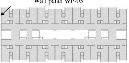
Wall panel WP-05
FIGURE 1. ETABS VIEW OF THE FLOOR PLAN OF THE BUILDING (Courtesy: L&T Ltd.)
Stuctural Stability
The stability of the structure was considered against the gravity loads, lateral loads from wind and earthquake, and the accidental loads like explosion. The precast design followed an emulation of cast-in-place system. Inter-connected walls are provided in orthogonal directions. The wall joints are such that an entire wall acts as an equivalent monolithic system under lateral loads. The connections between different panels are wet connections, and are able to transfer in-plane shear, flexural tension and compression. Toilet pods, which are U-shaped units, act as small core units. The wall-to-floor area ratio is 5.7% for shorter direction and 2.2% for longer direction.
Connections
Horizontal Joint: A horizontal connection betweenpanels transfers vertical stresses due to gravity loads
and any out-of-plane bending due to eccentricity of the loads. It also transfers vertical stresses due to cantilever action of the wall and horizontal shear under lateral loads. The horizontal joint between panels at a floor level is made by projecting dowel bars from the lower panel. They are inserted into the dowel tubes provided in the upper panel and grouted at site using non-shrink, non-metallic grout. Shear force is transmitted by dowel action of the bars. Any shear capacity of the grout is ignored. The dowels are designed to generate their tension capacity. They are placed continuously from the foundation to the roof. Tie reinforcement overlapped with U-bars are provided in the slabs for slab-to-wall connection. Figure 2 shows a typical detail of horizontal joint.
FIGURE 2. TYPICAL CROSS-SECTION OF A HORIZONTAL JOINT (All dimensions in mm)
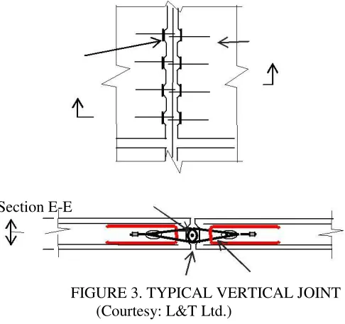
Vertical Joint: The vertical joints are designed to transfer shear forces under lateral loads. Figure
Section E-E
FIGURE 3. TYPICAL VERTICAL JOINT (Courtesy: L&T Ltd.)
The joint faces are indented to provide shear keys(9) for shear transfer with increasing lateral loads. Beyond cracking of concrete, a strut-and-tie action is expected to develop. Overlapping reinforcing loops are provided along with shear keys to take up the horizontal component of the inclined compressive strut. A continuous vertical bar is provided inside the overlapping loops from the adjacent units. The loops thus couples the adjacent panels.
For sufficient out-of-plane support, a panel is adequately connected to the perpendicular panel through overlapping reinforcing loops with the vertical bar. The exterior wall panels along the shorter direction of the building, which constitute the primary shear walls to resist the lateral forces, are provided with six shear keys per storey height. In interior wall joints, reduced number of reinforcement loops are provided per storey height since the shear demand is less.
Modelling
The analysis of the structure was carried out using the ETABS software package. The entire superstructure was modelled primarily using shell elements. The walls were of shell elements and the slabs of membrane elements. A floor was considered as a rigid diaphragm at the respective level, to transfer the lateral forces to walls. The horizontal joints of the wall panels were idealised to simulate an equivalent monolithic behaviour, in presence of the continuous vertical dowel bars. Therefore, the shell elements representing the panels were made continuous at the floor levels. A few beams and columns present in the structure were modelled using frame elements.
In absence of a model for shear transfer; the vertical joints between the panels were modelled as two extreme conditions as follows.
Integrated Model: In this case, perfect shear transferwas assumed through monolithic behaviour of two
Discrete gap model: In this model, no shear force wasassumed to transfer between the wall panels. To idealise this condition, a 20mm gap was provided at the vertical joint locations. This uncoupled the adjacent walls. The walls were connected only at the floor levels by the diaphragm constraints. Figure 4 (b) shows the gaps at the location of two joints in the discrete gap model.
20mm 100mm gap strip
(a) Integrated Model (b) Discrete gap model
FIGURE 4. SIDE VIEWS OF COMPUTATIONAL MODELS (TOP PORTION CROPPED)
Comparative Study of Models
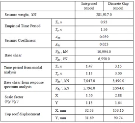
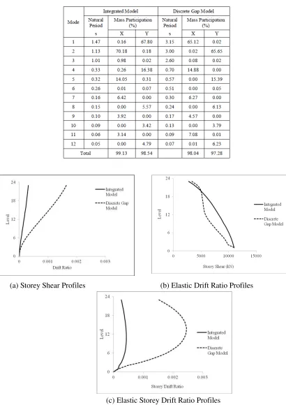
The variables for response spectrum analysis of the two models are shown in Table 1. The natural periods and mass participation in each mode, for the two models, are shown in Table 2. The responses of the two models were compared and the results are shown in Figure 5.
TABLE 2. NATURAL PERIODS AND MASS PARTICIPATIONS FOR FIRST 12 MODES
(a) Storey Shear Profiles (b) Elastic Drift Ratio Profiles
It was observed from the results that, when a vertical joint was modelled as a gap, the resulting structure was more flexible and higher modes were more predominant in the structure. When comparing the drift profiles, the integrated model showed a first modal shaped variation along the height of the building, while the gap model showed the effect of combination of higher mode shapes. Even though the top displacement was higher in the gap model, the drift in both the models were within the allowable limit of 0.4%.
Observations on Design
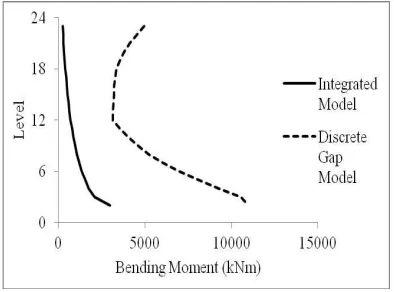
The final design forces were based on the higher values from the two models. To compare the design forces from the two models, a representative external wall panel, WP-05, in the shorter direction of the building was considered. The position of WP-05 is shown in Figure 1. Figures 6 and 7 present the graphical representations of the various forces developed in the panel in two models, from the worst case load combination which was 1.5 (DL+ SPEC-Y).
FIGURE 6.BENDING MOMENT VARIATION ALONG HEIGHT OF WP-05 FOR LOAD COMBINATION 1.5(DL+SPEC-Y)
FIGURE 7. AXIAL FORCE PROFILES OF WP-05 FOR LOAD COMBINATION 1.5(DL+SPEC-Y)
1.3m from foundation till roof through the precast walls. From the shear and tension force demand, this constant length of dowel bars was found to be more than the requirement in many locations. This conservatism led to a reduction in the overall economy of the project.
3.PREVENTION OF PROGRESSIVE COLLAPSE
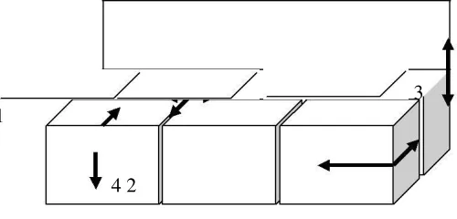
The Precast structures are more sensitive to progressive collapse after important local damage. For the stability of structure, three dimensional interactions between structural members are necessary to produce a robust design. The connections are normally designed for shear and compression. But in the case of accidental loading like explosion, high tensile stresses along with large deformations will occur. To take up such forces, the connections should have sufficient strength, continuity and ductility. Strength is to take up the extra forces acting, continuity to redistribute the loading in case of accidental collapse and ductility to accommodate large deformations as well as for energy dissipation. To take care of these demands, tie reinforcements in all the three dimensions are an absolute necessity (Cl.16.5, ACI 318-08). Figure 8 schematically shows the provision of tie reinforcement in the structure. The internal ties are to take up the lateral forces from shear wall action. Peripheral ties ensure the diaphragm action of the slabs. Floor to wall ties take up the horizontal forces from anchorage of floors to their support and vertical ties ensure the cantilever action of walls.
3 1
4 2
1. INTERNAL TIES
2. PERIPHERAL TIES
3. VERTICAL WALL TIES
4. FLOOR-TO-WALL TIES
FIGURE 8. TYPICAL TIE CONNECTIONS IN THE BUILDING
4.SUMMARY
The case study provided some information on the design and modelling aspects of a wall type precast building. The modelling of vertical joints was done with two extreme conditions, since there is no proper guidelines to model the joints more economically by considering the actual shear transfer.
The conclusions drawn from the case study on a precast wall panel system building are as follows.
The emulative monolithic wall system seems to be adequate in moderate seismic zones. The provisions of tie reinforcements, reinforced shear keys and dowel bars provide the required structural integrity for the precast system.
The modelling of vertical joints without considering the shear transfer through the shear keys, reinforced with shear links, lead to a conservative design. Non-linear shear springs can be incorporated in the model to get more realistic wall forces. This will lead to a more economical design.
ACKNOWLEDGEMENT
The authors are indebted to Mr.Sudheer Bommi of L&T ECC Chennai, for the contributions in developing the computational model.
REFERENCES
[1] ACI 318:08 2008. Building Code Requirements for Structural Concrete and Commentary, American Concrete Institute, USA.
[2] BS 8110-2:1985. British Standard: Structural use of Concrete-Part 2: Code of Practice for special circumstances, British Standard Institution.
[3] IS 11447 – 1985 (Reaffirmed 2003), Indian Standard Code of Practice for Construction with Large Panel Prefabricates, Bureau of Indian Standards, New Delhi.
[4] IS 15916:2010, Indian Standard: Building Design and Erection using Prefabricated Concrete-Code of Practice, Bureau of Indian Standards, New Delhi.
[5] FIB Bulletin-27, 2003. Seismic design of precast concrete building structures, International Federation for Structural Concrete.
[6] FIB Bulletin-45, 2008, Practitioners' Guide to Finite Element Modelling of Reinforced Concrete Structures, International Federation for Structural Concrete.
[7] Bachmann, H., and Steinle, A., 2011. Precast Concrete Structures, Ernst & Sohn Gmbtt & Co.KG., Germany. [8] Elliot, K.S., 2002. Precast Concrete Structures, Butterworth- Heinemann, Oxford.