Structural Optimization and Design of Electric
Transmission Tower
Sayed Abul Hossain1, Bibek Samanta2
Asst. Professor, Dept. of CE, CIET, Bardhaman, India 1 B.Tech Student, Dept. of CE, CIET, Bardhaman, India2
ABSTRACT:Transmission tower have been playing an important role in the power sector and also human life. The paper is focused on optimizing the steel transmission tower. The growing demand for electrical energy can be more economically through developing minimum weight of the tower.Structural design is a crucial topic in engineering since it allows to pro- pose solutions to multiple challenges in modern societies. Design process has been continuously studied and applied in real problems in engineering and many other disciplines. However, this kind of procedures to propose adequate designs has become insufficient nowadays. Design methods need to be reformulated by including optimization techniques since traditional designs are usually effective but they are not the most efficient, in general. In this paper the authors propose an optimization methodology that al- lows to obtain more efficient solutions than conventional designs of high voltage transmission line towers. The present work, an attempt have been made to make the transmission line tower price effective. The main focus is the design of a 33KV double circuit transmission line tower with rectangular base self-supporting lattice tower, which optimize the present geometry. Then, the structural behavior of existing tower is studied and Excel programs are developed for calculation of load and by STAAD PRO, evaluation we found the axial stress, compressive stress of the tower member. The structure was modelled and analyzed in STAAD. PRO, the weight of the transmission tower optimized while keeping the base width, heightof the tower and basic outline of the tower.
KEYWORDS:Structural Optimization, Transmission Tower,
I. INTRODUCTION
II. FACTORGOVERNINGTOWERCONFIGURATION
(a) The mid span clearance required from the dynamic behaviour of conductor and lightening protection of the line. (b) The minimum clearance to be maintained between conductors and between conductor and tower.
(c) The minimum clearance of the lower conductor is above ground level. (d) The location of ground wires with respect to the outermost conductor.
.
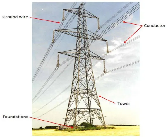
Figure 1.1 Transmission line tower
III. ANALYSIS OF TRANSMISSION LINETOWER 3.0 Technical Specification Given:
Location of project = Durgapur, Maximum temperature = 47 deg C Minimum temperature = 5 deg C, Basic wind speed (m/Sec) = 47 m/s Seismic Zone = III, Wind Zone = IV Reliability level = II, Terrain category = III
3.1 Specification of Tower:
Ruling span between two towers = 80.00m Minimum ground clearance of conductor = 0.7460 Ultimate tensile strength of conductor = 6734.00 kg Factor of Safety = 4.00
Yung modulus of elasticity = 80000.00 kg/m2 (For final) Yung modulus of elasticity = 0.4675 E6 kg/m2 (For initial)
3.2 Calculation of Wind load
Basic wind speed Vb = 47 m/s
Reference wind speed = VR = Vb/Ko= 47/1.375 = 34.182m/s
Design wind speed Vd= VR*K1*K2 K1=1.07,K2= 1.06
Vd = 34.182*1.07*1.06 = 38.77m/s
Design wind pressure Pd = 0.6*Vd = 0.6*38.772= 902 N/m2
Max. Temperature of conductor = 750C Max. Temperature of earth wire = 530C Everyday temperature = 320C Min. temperature = 00C
For 33KV:Conductor wire
The wind pressure applied on conductor = / × × = / × . × . = . /
Total wind load on conductor = × ×
= 1,Gc = 2.60
For 100% wind, %= 1.12×1.00×2.60 = 2.912 kg/m
For 36% wind, %= 0.36× 1.12×1.00×2.60= 1.04832 kg/m
For 75% wind, % = 0.75×1.12×1.00×2.60 = 2.184 kg/m
3.3 Computation of loading factor for power conductor :
Loading factor for still wind pressure on conductor ( ) = 1.00
Loading factor for 36% wind pressure on conductor ( ) = ( + ) / /w
W= Self weight of conductor= 0.7460 kg/m, =Design wind pressure applied on conductor=1.04832kg/m Loading factor for 36% wind load considered ( ) =(0.7460 + 1.04832 ) /0.7460
= 1.725
Loading factor for 75% wind pressure on conductor ( ) = ( + ) / /w
W= Self weight of conductor= 0.7460 kg/m, =Design wind pressure applied on conductor=2.184kg/m Loading factor for 75% wind load considered ( ) =(0.7460 + 2.184 ) /0.7460
= 3.558
Loading factor for 100% wind pressure on conductor ( ) = ( + ) / /w
W= Self weight of conductor= 0.7460 kg/m, =Design wind pressure applied on conductor=1.04832kg/m Loading factor for 75% wind load considered ( ) =(0.7460 + 1.04832 ) /0.7460
= 3.935
3.4 Computation of maximum Tension and Sag for power conductor:
Consider the supports of conductors are at one level. The horizontal component of wire pull T (Tension) BY parabola equation
2 2 2 2 2 2
2 1 2
2 2 1 2
1
24
24
c c
W
q
L
E
A
W
q
L
E
A
T
T
T
T
,
Dividing the expression by A and introducing the notation f for stress and also introduce = . ℎ
2 2 2 2 2 2
2 1 2
2 2 1 2
1
24
24
c c
q
L
E
A
q
L
E
A
f
f
f
f
Now the temperature factor for ( × × ) as under -: Temperature difference t = −
Loading factor -:
= =0.7460/1.58 = 0.47215 kg/cm2/m
Tension factors as under -:
At still wind condition = 1
2 2 2 2 2 2
1 0.4722 1.00 80 80000
4755784.86
24 24
c
q L E
Z
At 36% wind pressure on conductor = 1.725
2 2 2 2 2 2
2 0.4722 1.725 80 80000 14154315.88
24 24
c
q L E
Z
At 100% wind pressure on conductor = 3.935
2 2 2 2 2 2
3 0.4722 3.935 80 80000
73654647.97
24 24
c
q L E
Z
Working stress of conductor as under –:
Working tension in conductor = 6734.00/4 = 1683.5 kg
Working stress of conductor f = /A =1684/1.58 = 1065.51 kg/cm2
Stress constant as under -:
Now find the stress constant K given by formula
Put
2 2 2 2 2 2
1
1 2
1
0.4722
1.00
80
80000
1065.51
1061.317
24
24 1065.51 1065.51
c
q
L
E
A
K
f
f
So the above equation will be
f
22
f
2
K t
E
c
Z
Case- I : Starting Condition : Conductor temperature 5 C (minimum) & 100% wind pressure applied
The equation for final stress
2 2 2 2 2 2 3 2 2 3 2 2 2 2 1061.317 38.4481061.317 38.448 73654647.97
1099.77 73654647.97
1030.3970 c
f f K t E Z
f f Z
f f f f f
So = 1030.3970 kg/cm2
Tension of conductor:
T= ×A = 1030.3970 ×1.58 = 1628.03 kg
Sag of the conductor at mid span-:
Deflected Sag 2 3 2
2
80 0.4722 3.935 1.44
8 8 1030.40
D L q S m f
Angle of declination 1 1 0
1
ta n W /W ta n (0 .2 91 2 / 0 .7 46 ) 7 5.6 3
from vertical
Sag table at different cases and height of tower:
Case No. Description of cases Tension at mid span
of conductor (kN)
Deflected Sag (SD)
Vertical Sag (SV)
Length of conductor(L)= L+(W2 x L3)/(24 x T2)
I Conductor temp of and 100%
wind pressure applied
1628.027 kg = 16.28 kN
1.44 m 0.36 m 80.00 m
II Conductor temp of and 36% wind
pressure applied
1755.743 kg = 17.557 kN
0.59 m 0.34 m 80.00 m
III Conductor temp of and no wind
pressure applied (still wind)
852.295 kg = 8.523 kN
0.00 m 0.70 m 80.02 m
IV Conductor temp of and 100%
wind pressure applied
1769.654 kg = 17.697 kN
1.33 m 0.33 m 80.00 m
V Conductor temp of and 100%
wind pressure applied
17331.115 kg = 17.331 kN
1.36 m 0.34 m 80. 00 m
GEOMETRY OF TOWER
Height of the tower= 30m
Base width of the tower= 6m
Length of every wings of the tower =4.12m
Ground clearance =5.60m
Vertical spacing of conductor= 0.45m
Horizontal spacing of conductor= 0.45m
Height of Insulator string = 1.82m
Fig2:-Cable Loads acting on transmission tower
IV.RESULT
4.0 Compression and Tensile force acting on the tower and obtained from STAAD Pro-V8i are as,
LEG MEMBER BRACINGS OTHER DIAGONALS
Bea m
L/C Compres s-ion kg
Tension Kg
Beam L/C Compress-
ion kg Tension Kg Beam L/C
Compress- ion kg
Tension Kg
34 1
3.45E+05
4.54E+05 5 1 14841.721 -18561.540 111 1 -0.985 0.893
35 1
1.98E+05
4.35E+05 11 1 15860.281 -19121.327 112 1 0.943 0.839
36 1
1.55E+05
4.60E+05 16 1 16901.445 -21732.498 113 1 0.998 0.917
37 1
2.34E+05
4.28E+05 33 1 17650.345 -20672.245 114 1 0.118 0-936
185 1
2.65E+05
3.70E+05 70 1 4560.368 21328.234 122 1 0.925 0.674
186 1
2.44E+05
3.23E+05 71 1 5643.345 21563.345 123 1 -0.945 0.698
187 1
2.48E+05
3.4 9E+05 87 1 4175.298 18745.327 124 1 0.820 0.705
201
2 1
4.87E+05
3.18E+05 88 1 4347.367 19665.720 125 1 -1.265 0.715
202 1
4.67E+05
3.15E+05 89 1 4347.3676 19374.713 126 1 0.385 0.729
203 1 4.46E+05 3.12E+05 90 1 4347.367 19427.460 127 1 0.482 0.714
204 1 4.40E+05 3.10E+05 91 1 4347.367 19761.320 143 1 -0.489 0.732
205 1 4.16E+05 3.08E+05 92 1 4347.367 19162.254 144 1 0.798 0.740
206 1 4.24E+05 3.05E+05 99 1 5120.265 20365.185 145 1 -0.842 0.741
310 1 3.38E+05 2.38E+05 100 1 5367.456 20985.905 146 1 0.741 0.743
3111
1 1 3.10E+05 2.45E+05
4.1Different Values of stresses obtained from STAAD - Pro V8i are
V.CONCLUSION
The optimal designs obtained satisfy all the specifications included in the actual norms and can be directly applied in practice since they satisfy all the safety conditions imposed. According to this idea, real structuralmodels are analyzed by using 3D articulated latticed structure models.From the above study it is found that this type of design based on finite element modeling is essential for the design of tower structure. However it can be also concluded thatWind load in static manner may always is not effective for this type of tall towers . Dynamic wind loading has to be considered for a\nalysis and design of tall towers.Wind load is predominant in this type of tall tower structures rather than seismic force. Temperature load is also an important action in case of transmission line towers. Also the sag tension for different ambient temperature is important. A sag template shall be prepared for the determining sag scenario of the conductors.
OTHER DIAGONALS
Beam L/C
Axial N/mm2
111 1 -0.009
112 1 0.008
113 1 -0.007
114 1 0.003
115 1 0.005
116 1 -0.004
117 1 0.002
118 1 -0.03
121 1 0.02
122 1 0.005
123 1 -0.006
124 1 0.002
125 1 -0.007
126 1 0.005
127 1 0.004
143 1 0.006
144 1 0.003
145 1 0.002
146 1 -0.001
147 1 0.004
LEG MEMBER Beam L/C
Axial N/mm2
34 1 650.00
35 1 606.05
36 1 597.30
37 1 650.10
38 1 653.12
72 1 -636.08
75 1 -630.05
78 1 -487.24
82 1 397.34
185 1 580.05
186 1 622.94
187 1 424.17
201 2
1 590.09
202 1 370.09
203 1 452.35
204 1 672.56
205 1 334.17
206 1 234.20
310 1 483.78
311 1 524.05
BRACINGS Beam L/C
Axial N/mm2
5 1 93.85
11 1 -75.15
16 1 69.45
33 1 10.35
37 1 9.19
63 1 170.00
64 1 125.80
65 1 -172.70
69 1 8.371
70 1 -6.46
71 1 -9.48
87 1 14.50
88 1 -17.80
89 1 -129.80
90 1 -138.80
91 1 -243.70
92 1 -250.71
99 1 -8.37
100 1 -18.23
REFERENCES
1. Y. M. Ghugal, U. S. Salunkhe “Analysis and Design of Three and Four Legged 400KV Steel Transmission Line Towers: Comparative Study ” International Journal of Earth Sciences and Engineering 691 ISSN0974-5904,
2. Volume 04, No 06 SPL, October 2011, pp 691-694
3. V. Lakshmi1, A. Rajagopala Rao “ Effect Of Medium Wind Intensity On 21M 132kV Transmission Tower” ISSN: 2250–3676 Volume-2, Issue-4, 820 –824
4. Towers: Comparative Study ” International Journal of Earth Sciences and Engineering 691 ISSN 0974 -5904, 5. Volume 04, No 06 SPL, October 2011, pp 691-694
6. M.Selvaraj, S.M.Kulkarni, R.Ramesh Babu “Behavioral Analysis of built up transmission line tower from FRP 7. pultruded sections” ISSN 2250-2459, Volume 2, Issue 9, september 2012
8. S.Christian Johnson 1 G.S.Thirugnanam “Experimental study on corrosion of transmission line tower foundation and its rehabilitation” International Journal Of Civil And Structural Engineering ISSN 0976 – 4399 Volume 1, No1, 2010
9. F. Albermani, M. Mahendran and S. Kitipornchai “Upgrading of Transmission Towers Using a Diaphragm Bracing System” International Journal Of Civil And Structural Engineering Volume2, No2, 2008
10. N.PrasadRao, G.M.SamuelKnight, S.J.Mohan, N. Lakshmanan “Studies on failure of transmission line towers in testing” 11. G.Visweswara Rao “Optimum Designs For Transmission Line Towers” Computer & Structuresvol.57. No.1.pp.81-92, 1995
12. Ying-Hui Lei and Yu-Lin Chien, (2005)”Seismic Analysis of Transmission Towers Considering both Geometric and Material Nonlinearities”, Tamkang Journal of Science and Engineering, 8 (1), 29-42.
13. Faisal Abdullah Al-Mashary (1999) “Non-Linear Analysis of Transmission Towers”, J.King Saud Univ, 11 (1), 19-32.
14. Mohamed Mohsen El-Attar (1998) ”Non-linear dynamics and seismic response of Power Transmission Lines”, PhD Thesis, McMaster University, Canada
15. Guide for design of steel transmission towers by American Society of Civil 16. Engineers, American Society of Civil Engineers Task Committee on Tower Design 17. Design of Latticed Steel Transmission Structures: (ASCE 10-97)
18. International Journal of Advanced Engineering, Management and Science (IJAEMS)[Vol-1, Issue-4, July- 2015]
• I.S. 802: Part 1: Sec: 1:1995: “Code of Practice for Use of Structural Steel in Over Head Transmission Line Towers-Materials and Loads. • I.S. 802: Part 2: Sec: 1:1995: “Code of Practice for Use of Structural Steel in Over Head Transmission Line Towers-Permissible Stresses. • I.S. 5613: Part 2: Sec: 1: 1989: Code of Practice for Design, Installation and Maintenance for Over Head Power Lines: Lines above 11
KV And Up to And Including 220 KV: Design.
• I.S. 5613: Part 2: Sec: 2: 1989: Code of Practice for Design, Installation and Maintenance for Over Head Power Lines: Lines above 11 KV And Up to And Including 220 KV: Installation and Maintenance.