Robotic modeling and simulation of palletizer robot using Workspace5
Nory Afzan Mohd Johari, Habibollah Haron, Abdul Syukor Mohamad Jaya
Department of Modeling and Industrial Computing
Faculty of Computer Science & Information Systems,
Universiti Teknologi Malaysia, 81310 UTM Skudai, Johor, Malaysia
[email protected], [email protected],[email protected]
Abstract
Employment of robots in manufacturing has been a value-added entity in a manufacturing industry. Robotic simulation is used to visualize entire robotic application system, to simulate the movement of robot arm incorporated with components consist in its environment and to detect collision between the robot and components. This paper presents result of a project in implementing a computer based model to simulate Okura A1600 palletizer robot. The application uses Okura A1600 robot for palletizing bags at the end of the production line and focuses on pick-and-place application. The project objective is to generate a computer simulated model to represent the actual robot model and its environment. The project simulates the robot’s first four joints, namely as the Waist, Shoulder, Elbow and Waist and focuses on the position of the robot’s end effector, regardless its orientation. Development of the model is using Workspace5 as a simulation tool. Two types of methodology are used, which are the methodology for developing the robotic workcell simulation model and the methodology for executing the robotic simulation. The output of the project will be a three-dimensional view of robot arm movement based on series of predefined Geometry Points, layout checking and robot’s reachability by generating working envelope, collision and near miss detection, and monitoring on the cycle time upon completing a task. The project is an offline programming and no robot language is generated.
Keywords: Robotic modeling, Simulation, CAD, Workspace5
1. Introduction
Employment of robots in manufacturing has been a value-added entity for the company in gaining their competitive advantages. Zomaya [1] describes some features of robots in industry, which are decreased cost of labor, increased flexibility and versatility, higher precision and productivity, better human working conditions and displace human working in hazardous and impractical environment.
Farrington et al.[2] states that robotic simulation is different from traditional discrete event simulation (DES) in five ways in terms of some features and capabilities. Robotic simulation covers the visualization of how the robot moves through its environment. Basically, the simulation is heavily based on CAD and graphical visualization tools. Other type of simulation is numerical simulation, deals with dynamics, sensing and control of robots. It has been accepted that the major benefit of simulation is reduction in cost and time when designing and proving system (Robinson [3]).
Robotic simulation is a kinematics simulation tool which primary use are as a highly detail, cell-level validation tool (Farrington et al. [2]) and for simulating a system whose state changes continuously based on the motion(s) of one or more kinematic devices (Roth [4]). It is also a tool to verify robotic workcell process operations by providing “mock-up” station of robots application system, in order to check and evaluate different parameters such as cycle times, object collisions, optimal path, workcell layout and placement of entities in the cell with respect to each other.
The palletizing process follows a standard movement patterns consists of seven steps that represent path of the robot arm moving from the pick-up station towards the pallet and back to the pick-up station. Figure 2 shows the movement pattern.
This paper is divided into five sections. Section 2 presents the current robotic application system. Section 3 discusses the methodology for the robotic workcell development and simulation. Some simulation and results are presented in Section 4 and conclusions are drawn in Section 5.
2. The Robot and the Robotic Palletizing
System
This section presents the robot and its application system of the current system. The application uses Okura A1600 robot for palletizing bags at the end of the production line and focuses on pick-and-place application. The robot will pick bags at the pick up point and place the bags onto a pallet.
The robot model is multi-articulated four-axis pneumatically powered Okura A1600 Palletizer. It has the fastest cycle times in robot class, which is up to 1600 cycles per hour, with high reliability and low maintenance requirements. The robot is capable to handle capacity up to 140kg. It also provided with high
accuracy, which is 1mm of repeatable position precision. Figure 2. The movement pattern
The robot consists of a few components, namely as the Base, Rotor/Link1, Lower/Link2, Upper arm/Link3, Link lever/Link4, Flange/Link5, Motor D-axis1 and Motor D-axis2. Positioning of the robot is based on its Hand Coordinates System. Hand coordinates employ three-dimentional coordinate system based on the three axis (X, Y and Z).
Each pallet will consists of ten layers with five bags at each layer. The bags are arranged based on specific bags arrangement. Figure 3 shows the bags arrangement.
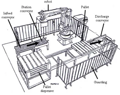
The robotic palletizing system consists of Okura A1600 robot palletizer, conveyor system for transporting bags and pallets, pallet dispenser, guarding that provides boundary for robotic workcell and control panel for supervision and control with human-machine interface. Figure 1 shows the robotic workcell.
Figure 3. Bags Arrangement
3. Methodology
This section present the Workspace5 as a simulation tool and the methodologies in developing the model and execution of the simulation. Workspace5 is PC-based robot simulation software that supports three-dimensional visualization. Some features of Workspace5 are collision and near miss detection, CAD functionalities that are similar to ACIS graphics kernel as AutoCAD, reach checking for optimization in robot placement, and offline programming.
i) Creatingpartmodels There are two types of methodology being applied,
which are the methodology for developing robotic workcell simulation model by Cheng [5] and the methodology for robotic simulation by Grajo et al. [6]. Figure 4 shows the methodology by Cheng [5] and methodology by Grajo et al. is shown in Figure 5.
Part model is a low-level or geometric entity. The parts are created using basic elements of solid modeling features of Workspace5. These parts consist of the components of Okura A1600 and the devices in its workcell such as conveyor, pallet and pick up station.
ii) Building devicemodels
Device models represent actual workcell component and categorized into two; robotic device model and non-robotic device model. Building device model starts from positioning the base of part model as the base coordinate system. Okura A1600 consists of five links, which are Rotor/Link1, Lower/Link2, Upper arm/Link3, Link lever/Link4 and Flange/Link5. These links are attached accordingly to its number by using the attachment feature of Workspace5. Each attached link is subjected to Parent/Child relationship.
Figure 4 A methodology for developing robotic workcell simulation models by Cheng [5]
Phase 1: Define the problem
Phase 2: Design the study
Phase 3: Design the conceptual
model Phase 4:
Formulate inputs, assumptions, and process
definition
Phase 5: Build, verify, and validate
the simulation model
Phase 6: Experiments with the
model and look for opportunities for Design of
Experiments
Phase 7: Documentation and
Presentation Phase 8:
Define the Model Life Cycle
iii)Positioning device models inlayout
The layout of workcell model refers to the environment that represent the actual workcell. As for this case, the coordinates system being applied is the Hand Coordinates System of Okura A1600. Placement of the model and devices in the environment is based on the actual layout of the workcell.
iv)Defining devices’ motion destination inlayout
The motion attributes of device model defines the motion limits of the joints of the device model in terms of home, position, speed, accelerations, and travel. In Workspace5, each joint is considered part of the proceeding link. As in Okura A1600, joint 1 is a waist joint which links between the Base and the Rotor/Link1, joint 2 is a shoulder joint which links between the Rotor/Link1 and the Lower/Link2, joint 3 is an elbow joint which links the Lower/Link2 with the Upper arm/Link3, joint 4 is a wrist joint that links the Upper arm/Link3 with the Link lever/Link4, and joint 5 is a gripper joint, which links the Link lever/Link4 with the Flange/Link5. Each joint has its own motion limits. Once the joints have been defined, Workspace5 will automatically defines the kinematics for the robot.
Figure 5. A methodology for robotic simulation by Grajo et al. [6]
3.1 The Methodology for Developing Robotic Workcell Simulation Model
v) Device behaviour andprogramming Robotic workcell simulation is “a modeling-based
problem solving approach that aims to sufficiently produce credible solutions for robotic system design” (Cheng [5]). His methodology consists of six steps:
Modeling the robot application focuses on three activities, which are building the robot, motion path programming of the palletizing process and run the simulation. Building the robot’s model is heavily based on the geometrical data of Okura A1600 using the CAD features of Workspace5. The dimension is refers to the CAD drawing of Okura A1600.
Positioning the GP and the series is based on the movement pattern and the bags arrangement.
The GP coordinates are entered by using the Pendant features of Workspace5. There are three ways in creating the GP, which are by entering the value for each joint, enter the absolute value of X, Y and Z, and by mouse clicking. As for this project, the most appropriate way to acquire the accurate position is by entering the absolute value of X, Y and Z of a GP. 74 GPs have been identified during the development.
Few spatial data needs to be considered in determining the motion path:
a) Point at the pick up station where the robot will pick the bag,
vi)Executing workcell simulation andanalysis
b) Five points that represent an arragement of bags in an odd numbered layer.
The simulation focuses only at the position of the robot arm, not including its orientation. After programmed, the device model layout can be simulated overtime. Execution of the simulation and analysis is using the features of Workspace5. The simulated model is capable to view the movement of robot arm, layout checking, robot’s reachabilites, cycle time monitoring and collision and near miss detection.
c) Five points that represent an arragement of bags in an even numbered layer.
Position of points is in x, y and z coordinate. Since each pallet consists of ten layers of bags with five bags on each layer, ten incremental value of z are needed.
v) Phase 5: Build, verify, and validate the simulation model
3.2. The Methodology for Robotic Simulation
During this phase, development of the robotic workcell is based on the methodology proposed by Cheng [5]. This is an iteractive phases which aim to improve the model’s precision and motion.
The methodology consists of eight phases but the project only executes up to seven phases:
i) Phase 1: Define the problem
Validation towards the model is based on the visualization of system layout and robot’s cycle time in completing a task. The layout generated using Workspace5 is compared to the actual system layout. Figure 6 shows the system layout in Workspace5. Problem identification is defined during the
preliminary analysis of problems’s background. Current system have no computer based model that represent the robotic application. Thus, it is impossible to monitor and evalute the performance of the robotic palletizing system.
ii) Phase 2: Design the study
The study is limited to the project scopes. This phases acquire appropriate decisions for tools and methodology that are going to be used. Besides, a proper planning and milestone need to be done.
iii) Phase 3: Design the conceptual model
The conceptual model is using the current application of the robotic system. This phase acquires collection of data of the parameters for the robotic workcell development. These data include layout of the robotic applications, geometry configuration of the robot, robot motion parameters and the robot cycle time.
Figure 6. The system layout in Workspace5
During preliminary data gathering, a movie that shows the actual robot performing a task in one day operation is recorded. The model is assumed to represent the actual system once operated at the same movement iv)Phase 4: Formulate inputs, assumptions, and process
of actual system and capable to perform at the similar cycle time as in the movie.
vi) Phase 6: Experiments with the model and look for opportunities for Design of Experiments
This phase is similar to the step six in the methodology by Cheng [5]. A simulation is run in order to visualize the arm movement and analysis on collision detection. Execution of the simulation is using the features of Workspace5 for simulation. Workspace5 allows layout checking in order to prepare other devices within the robot’s reachability. It also capable to generate working envelope for any namely two joints. During simulation, a cycle time is displayed. The simulation allows collision and near miss detection among robot joints and between the joints and any object within the workcell. This project is an offline programming. Neither robot language is generated nor impelementing at actual workcell.
Figure 7. The working envelope
b) Cycle time
Cycle time is refers to the total time taken by the robot in completing a task. During simulation, the cycle time is displayed at the bottom of the screen on the status bar. A simulation log is also generated. There is a slight difference in the cycle time of the real process and simulation, which is 11s. Therefore, the model robot is performed as similar as the real robot with an error rate is 1.39%
vi)Phase 7: Documentation and presentation
This phase gathers and documents all results generated from the simulation. A written report provide better understanding of the experiment’s executions and analysis.
4. Simulation and Result
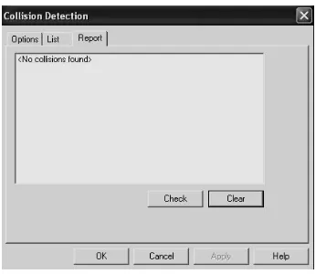
4.2. Collision DetectionWorkspace5 is capable to checks for any collision or near miss among the robot joints or between the robot joints and devices in the workcell. Example of the result is “no collision found” as shown in Figure 8.
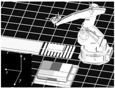
This section presents the execution of simulation to the first four joints of the robot, namely as the Waist (joint 1), Shoulder (joint 2), Elbow (joint 3) and Wrist (joint 4). It focuses only the position of the wrist, which is the value of x, y and z, regardless its orientation, which is the value of roll, pitch and yaw.
4.1. Validation of the Robot Model
Validation towards the model is done by layout checking and measuring the cycle time of the robot’s performance.
a) Layout checking
The working envelope shows the reachability of robot arm that represent the limits of robot operation and can be used safety purposes. Workspace5 has capability in calculating the working envelope of the robot. Figure 7 shows the envelope generated from the three first joints of the robot.
4.3. Animation [3] P. Robinson, “Robotics Education and Training: A Strategy
for Development”, Emerald Group Pub. Ltd, Journal of
Industrial Robot, vol. 23, no. 2, 1996, pp. 4-6.
An animation during simulation can be created. The animation is in .AVI format. Figure 9 shows the view of an animation.
[4] N. James and B. Roth, “On the Kinematic Analysis of Robotic Mechanisms”, The International Journal of Robotics Research, SAGE Pub., vol. 18, no. 12, 1999, pp. 1147-1160.
[5] F.S. Cheng, “A Methodology for Developing Robotic
Workcell Simulation Models”, Proceedings of the 32nd
Conference on Winter Simulation, IEEE, Dec. 2000, pp. 1265-1271.
[6] E.S. Grajo, A. Gunal, D. Sathyadev, and O.M. Ulgen, “A Uniform Methodology for Discrete-event and Robotic Simulation”, Proceeding of the Deneb Users Group Meeting. Deneb Robotic. Inc. pp. 17-24.
Figure 9. The animation
5. Conclusion
Robotic simulation is a modeling-based approach for analyzing performances of a robotic workcell. Unlike tradition discrete event simulation, robotic simulation emphasizes on detail study of robot behavior such as motion and interaction among other components in its environment. Robotic simulation provides highly-detailed three-dimensional visual layout of a workcell. Some simulation packages are incorporated with collision detection capabilities that allow user to identify any interference between robot and objects. It also provided with cycle time monitoring to verify how long a robot will complete a given task. Programming a robot with minimal cycle time will ensure higher productivity of a production. Compared to DES, robotic simulation packages have a capability to translate a programming made for the simulated model into the real robot programming language.
References
[1] Zomaya, A.Y., Modeling and Simulation of Robot
Manipulators: A Parallel Processing Approach, World
Scientific Publishing Co. Pte. Ltd, Singapore, 1992.
[2] O.M. Ulgen, S. John, C. Gene, S. David, R. Matt, W. Gemet, “Increasing the Power and Value of Manufacturing Simulation Via Collaboration with Other Analytical Tools: A Panel Discussion”, Int.Proceedings of the 31st Conference on
![Figure 4 A methodology for developing robotic workcell simulation models by Cheng [5]](https://thumb-us.123doks.com/thumbv2/123dok_us/1338294.1166802/3.612.84.272.317.540/figure-methodology-developing-robotic-workcell-simulation-models-cheng.webp)