An Effective Design and Implementation of
Software Defined Radio System
Sk.Masthanbasha1, Dr. Habibullakhan2
Research Scholar, Dept. of ECE, Acharya Nagarjuna University, Guntur, AP, India1
Dean (Student affairs), Dept. of ECE, K.L. University, Vijayawada, AP, India 2
ABSTRACT: A radio receiver is a device that picks upthe desired signal from the numerous signals propagating at
that time through the atmosphere, amplifies the desired signal to the required level, recovers from it original modulating signal and eventually displays it in the desired manner. This outline of functions that must be performed shows that the major difference between receivers of various types is in the way in which they demodulate the received signal and this in turn will depend on the type of modulation employed at the transmitter. The second major difference is the method of displaying the received signals. In this paper, Software Radio System was designed, implemented and the effects of potential channel disturbances were analyzed and compensated.
KEYWORDS: Software Radio System, Signals, Modulations.
I. INTRODUCTION
A Software Radio system is a transmitter and receiver system that uses digital signal processing for coding, decoding, modulating and demodulation the data. This paper focus on using the IEEE 802.11a specification to create a software radio. The feasibility of using Math works’ Simulink and Texas Instrument’s Code Composer Studio to design, test, and prototype an OFDM software radio system on a Texas Instruments CDSK6713 DSP development board was studied. Among the subjects examined were communication with the board through real time data exchange (RTDX), quadrature amplitude modulation (QAM), orthogonal frequency division multiplexing (OFDM), frame and carrier synchronization, and issues with Simulink DSP code generation for prototyping.
ISSN(Online): 2320-9801
ISSN (Print): 2320-9798
I
nternational
J
ournal of
I
nnovative
R
esearch in
C
omputer
and
C
ommunication
E
ngineering
(An ISO 3297: 2007 Certified Organization)
Vol. 4, Issue 9, September 2016
allows experimentation with new techniques and devices without the need to replace the entire set of boards. An exciter provides 1/2W of RF over the same range or into the VHF and UHF range using image or alias outputs.
II.RELATED WORK
A.TYPE I: HARDWARE MODEL
Fig. 1. Analog Receiver Block Diagram.
This SDR must even find solutions to channel and user entire schema from antenna to speaker. As in Fig.1The RF frequency entered in the antenna will be first amplified and filtered to the bandwidth that must be selected. The local oscillator, LO, will down convert the RF signal into new intermediate frequency, IF, that can be treated, filtered and amplified as necessary. Finally, when the expected IF is found, it can be demodulated using the appropriate schema, as FM or SSB or VSB demodulator, just to name some examples. The base band signal, from DC to 4 kHz, as the audio signal, will appear after the demodulator and problems, increasing or decreasing the SNR, the power density, the bit rate, the compression and the security level as the need. The capability to redo itself is required and innovations in the antenna are Fundamental. The beginning of the effort to create a SDR (platform that can transmit RF signals over software applicative) has started with the idea to improve a COTS amateur radio platform, which already a DSP with FM and SSB digital modulation.
Fig. 2. Digital radio
The signal quality is kept because digital filters are easier to be created and the frequency response is better than in analog filters. At last, the combination of a heterodyne circuit with a digital software radio is more be easily sampled with the commercial analog-digital converter. The suggested test bed will ratify the advantages and costs of these three sampling forms. Some comparisons with a commercial digital radio as shown in Fig.2 instead the proposed SDR platform will certainly be as referential datum.
B. TYPE II: FIVE PORT MODEL
Fig. 3. Software defined radio direct conversion receiver using proposed five-port
To get a spars D-1 matrix, the first step is to eliminate D-1’s elements. One of these relations is dependent of the others; so it can be removed and six ports will be reduce to five ports. By this way, the first column and the first raw of D-1 matrix will be eliminated. The second one is to set some elements as zero elements if possible. To get this objective, novel five-port architecture as shown in Fig.3 is proposed. This architecture uses a simple way to choose three independent outputs. This structure is very suitable for software defined radio applications. New structure reduced the number of ports to five ports, and it has a sparse D-1matrix due to zero setting of D-1’s elements. Thus, there are less constant parameters to calibrate than the other structures. It is only need to determine five constant parameters. The parameter reduction in D-1 matrix makes easier the calibration procedure and causes to mitigate the errors of demodulation equations, which are appeared in calibration procedure. A new demodulator based on five-port architecture has been proposed and simulated. Its main advantages are the higher isolation between its two inputs and the less constant parameters in its demodulation equations than the previous multi-port structures. Simulation studies are conducted to evaluate the performance of the proposed demodulator. The digital modulation schemes are examined and BER of a specific digital modulation
(QPSK) is simulated. These results can be generalized to the MPSK and MQAM modulations. Furthermore, the simulation and measured results show that this architecture is comparable to the other multi-port structures and is more suitable for SDR terminals as result of its advantages such as broadband specifications, ultra low power consumption, less ADC in compare to six-port structure, high isolation between its two inputs and easy calibration procedure.
III. PROPOSED SYSTEM MODEL
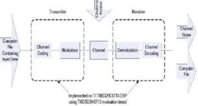
A software defined radio is a transmitter and receiver system that uses digital signal processing (DSP) for coding, decoding, modulation, and demodulation. This allows much more power and flexibility when choosing and designing modulation and coding techniques. The Texas Instruments TMDSK6713 evaluation board with the TMS320C6713 DSP chip was selected to implement the radio. The system functions are shown in Fig. 4
Fig. 4. I/O block diagram for Transmitter and receiver radio systems
ISSN(Online): 2320-9801
ISSN (Print): 2320-9798
I
nternational
J
ournal of
I
nnovative
R
esearch in
C
omputer
and
C
ommunication
E
ngineering
(An ISO 3297: 2007 Certified Organization)
Vol. 4, Issue 9, September 2016
board and/or stored on a computer file for further verification and analysis.
The input from the digital data source will be sent into the transmitter. There it will have channel coding applied to provide protection from data corruption introduced by noise. This part will not be implemented in this project. After that, the encoded digital signal will then be modulated with an appropriate modulation technique and transmitted through the channel. An appropriate model and representation for the channel also needs determined. After this, the receiver demodulates the signal and applies appropriate channel decoding. From there the reconstructed digital signal will be available for further analysis.
Two development boards were used to construct the radio system. One board was designated for the transmitter and the other for the receiver. The system will be constructed and programmed entirely ingopalax Publications & TCET downloaded to the board through TI Code Composer Studio for testing
Fig. 5. System Breakdown of the Software Radio
The input to the system will be digital data in a computer file. This data will be modulated by the transmitter and sent to the channel. The channel will introduce interference to the signal in the forms of attenuation, phase delay, and noise. At the receiver side, the signal will be demodulated and reconstructed to produce the original transmitted message.
The transmitter shown in Fig. 6. will generate the signal that will be transmitted through the channel. The transmitter signal is constructed using demultiplexing, quadrature amplitude modulation (QAM), orthogonal frequency division multiplexing (OFDM), and up mixing.
Fig. 6. Transmitter Subsystem Detailed Diagram
The demultiplexing block takes a byte of binary data and then breaks the byte into four 2-bit streams. These 2-bit streams are each fed into a QAM modulation channel. Once the QAM channels have modulated the input data, a buffer collects a group of 20 QAM symbols that represent 5 bytes of data. The group of symbols is then passed into the OFDM block. The OFDM system multiplexes the QAM signals together to produce the final modulated output. Interpolation increases the sampling rate and conditions the signal for transmission before it is modulated. This is implemented using a combination of up sampling and filtering. Mixing is done to meet the bandwidth requirements of the channel. The up mixer increases the frequency of the OFDM signal by multiplying it by a greater carrier frequency. The OFDM signal is imbedded in the carrier signal that the local oscillator produces. The output of the mixer is contained in bandwidth of the channel.
Fig. 7. Details of a channel
The channel attenuation models the attenuation or the gain effect that the channel has on the transmitted signal. This gain can vary with time and frequency. The multi-path interference models reflections of the transmitted signal. These reflections arrive at the receiver at different times. Each one of these paths has its own attenuation that can vary with time and frequency. Noise is also introduced into the signal. The noise is either specific to a limited frequency range (narrow band noise) or can affect the whole spectrum of the transmitted signal. The receiver subsystem shown in Fig.9 recovers the sent message. The receiver extracts the carrier, symbol, and frame timing from the signal. It uses this information to extract the message from the phase, frequency.
Fig. 8. Receiver Subsystem Detail
The frame synchronization synchronizes the data frames. This aligns the start time of the message so the digital data can be interpreted correctly. This allows the compute file or message to be translated back into its original form. The demodulation system consists of two parts: OFDM demodulation and QAM demodulation. The OFDM demodulation demodulates the signal into its constituent QAM sub signals. The QAM demodulation decodes the QAM carriers back into the bytes that were originally transmitted. The carrier synchronization subsystem corrects for frequency differences between the transmitter and the receiver. It also corrects for the phase delay introduced by the channel. The symbol synchronization determines the time to sample the pulses coming from the QAM modulation. This allows the most accurate information to be extracted from the pulse stream. The output is the digital data that was originally sent into the system. What follows are the theory, design and implementation of each of the radio subsystems detailed earlier. Quadrature amplitude modulation is a modulation scheme that creates a modulation signal from a binary bit stream. The binary data is broken up into bit sets. Each bit set is represented on a constellation. The position of the point on the constellation representing the bit set is mapped to in-phase and quadrature components using the complex envelope. According to Couch [1], the complex envelope can be expressed as:
g(t) = x(t) + jy (t) (1)
ISSN(Online): 2320-9801
ISSN (Print): 2320-9798
I
nternational
J
ournal of
I
nnovative
R
esearch in
C
omputer
and
C
ommunication
E
ngineering
(An ISO 3297: 2007 Certified Organization)
Vol. 4, Issue 9, September 2016
s(t) = x(t)cos(ωct)− y(t)sin(ωct) (2)
The data comes into the system one byte at a time. The byte of data is broken up into four pairs using the “extract bits” block. Once the bits are extracted, they are passed to a lookup table. The lookup table contains the QAM symbols representing each bit pair on the QAM constellation. The output of the QAM encoder blocks are complex numbers. The symbols are multiplexed together and converted into frame data. The buffer on the output of the convert to frame allows for multiple bytes to be placed into the OFDM spectrum.
IV. RESULT & DISCUSSION
Simulink
After completing the simulink model for software radio, it is tested by transmitting a test image through the transmitter model and received successfully.
The test image transmitted through the model is given as in Fig. 9.
Fig. 9. Test Image (Transmitted image)
The transmitted image is viewed before transmission as in fig 10. After transmitting through the model, the image is received successfully and is viewed at fig .11
Fig. 10. Test image before transmission (Image in Viewer) Fig. 11. Image out Viewe
Fig. 12. shown below defines that the picture is viewed while the image transmission occurs. Fig. 13. shows the
Fig. 12. Test image while transmitting Fig. 13. Test image while reception.
Fig.14. describes unsynchronized OFDMDemodulation plot for the developed software model.and Fig. 15. defines the OFDM Demodulationspectrum for the developed Software radio model.
Fig. 14. Unsynchronised OFDM Demodulation Plot Fig. 15. OFDM Demodulation spectrum
Fig. 16. explains that the discrete time scatter plot scope obtained for the developed Software radio model.
Fig. 16. Discrete time scatter plot scope
ISSN(Online): 2320-9801
ISSN (Print): 2320-9798
I
nternational
J
ournal of
I
nnovative
R
esearch in
C
omputer
and
C
ommunication
E
ngineering
(An ISO 3297: 2007 Certified Organization)
Vol. 4, Issue 9, September 2016
were analyzed and compensated. The design was converted into C code and loaded to the DSP board. Though the code was too slow to run on the DSP board, the model is working efficiently for both jpeg image and for a text message.
Without the help of debugger, the C code can be converted to DSP code with the help of code compose studio, the utility provided by texas instruments. Comparing to other models, it is reliable and effective approaches to check the transmission of signal at each and every stage developed with the help of simulink.
The model developed for verifying the transmission of a text jpeg image are,
QAM encoder
OFDMmodulator QAM decoder
OFDMdemodulator OFDM spectrum Soft Radio Scatter Plot
Figuring out the simulink diagram optimization so that the radio speed could be increased to run on the board Implement channel coding on the radio to reduce the error rate due to additive white Gaussian noise. Looking into implementing RF hardware to simulate Radio’s performance under real world conditions. Investigate Multilevel QAM and AGC in order to increase radio’s data rate. The rest of the carriers of OFDM frame could also be utilized to increase this.
REFERENCES
1. Mitola, Joseph and Zvonar, Zoran, “Software andDSP in Radio,” IEEE Communications Magazine,August 2006, P140-150. 2. Mitola,Joseph,et al,“Globalization of Software Radio,” IEEE Communications Magazine,February 2005,P82-83.
3. Tuttle bee, Walter H.W., “Software RadioTechnology: A European Perspective,” IEEECommunications Magazine, February 2003, p118.
4. Tsurumi, Hiroshi and Suzuki, Yasuo, “BroadbandRF Stage Architecture for Software Defined Radioin “Hand help Terminal Applications,” IEEE Communications Magazine, March 2004, P118.Pucher, Lee, “Paving Paths to Software Radio Design,” Communication systems design, June 2004, P19.
5. Shepherd, Rob,“Engineering and Embedded Software Radio,”IEEE Communications Magazine, November 2004, P70. 6. Introduction to SDRhttp://www.arrl.org.
7. “Basics of Software Radio Part,” RF Designline.com.
8. Richard van Nee, Ramjee Prasad, “OFDM for Wireless Multimedia Communication,” BritishLibrary Cataloguing in Publication Data. 9. “SystemC Verification Standard Specification version 1.0e”, May 2003, http://www.systemc.org
10. J.f. Boland, A.Chureau, C.Thibeault, Y.Savaria, F.Gagnon, Z.Zilic, “An Efficient Methodology for Design and Verification of an Equalizer for a Software Defined Radio”, in Proc. Of 2nd Northeast Workshop on Circuits and Systems, Montreal, Quebec, June 2004, pp.73-76.
11. The Open SystemC Initiative (OSCI) http://www.systemc.org
12. Grant Martin, “SystemC’s Role in an m\Multilingual World”, 8th European SystemCUsers Group, Stuttgart, November 2003.
BIOGRAPHY
SK. Masthan Basha: Received the B.Tech degree in ECE from JNTUH, Hyderabad , M.Tech degree in VLSI DESIGN from SATHYABAMA UNIVERSITY, Chennai, and is currently doing the research work in ACHARYA NAGARJUNA UNIVERSITY, Guntur, Andhra Pradesh, INDIA. His research interested areas includes wireless communications, Telecommunications ,microwave antennas and VLSI Design and having more than 8 international, national journals/conference papers in his credit.
Prof. Habibulla khan born in India, 1962. He obtained his B.E. from VRSiddhartha Engineering College, Vijayawada during 1980-84. M.E from C.I.T, Coimbatore during1985-87 and PhD from Andhra University in the area of Antennas in the year 2007.He is having more than 25 years of teaching experience and having more than 50 international,national journals/conference papers in his credit. Prof. Habibulla khan presently working as Dean (Student affairs), K.L.University. He is a fellow of I.E.T.E, Member IE and other bodies like ISTE. His research interested areas includes Antenna system designing,