The Effect of Joint Width between Blocks
in Concrete Block Pavement
Rachmat Mudiyono
1*, Hasanan Md. Nor
2and Tung Chai Ling
32
Faculty of Civil Engineering,
Universiti Teknologi Malaysia, 81310UTM Skudai, Johor, Malaysia Tel: +60-7-5531500, Fax: +60-7-5566157, E-mail: [email protected]
3
Faculty of Civil Engineering,
Universiti Teknologi Malaysia, 81310UTM Skudai, Johor, Malaysia Tel: +60-7-5531580, Fax: +60-7-5566157, E-mail: [email protected]
ABSTRACT
Jointing sand is the main component of concrete block pavement (CBP) that promotes load transfer between blocks. Often, when sands are available from various sources, it becomes a difficult task to judge the right source of sand. This paper presents the results of an experimental program, conducted to demonstrate a quick and simple technique, for selecting the right source of jointing sand for CBP. The optimum joint width between blocks is 3 mm. For joint widths less than the optimum, the jointing sand was unable to enter between blocks. A large amount of sand remained outside the joint sand heaps on the block surface.
Key words:
Concrete block pavement, width joint, jointing sand and sand grading.
1. Introduction
Concrete block pavement (CBP) consists of individual blocks of hand-sized units that are laid on a thin bed of sand, between edge restraints, overlaying a sub-base (Fig.1). The joint spaces are 2 to 7 mm and are filled with sand that is jointing sand. The presence of sand in the joints plays the biggest role in promoting load transfer between blocks. Frictional resistance is developed in the joints under load; this prevents the blocks from undergoing excessive relative displacements and transmits part of the load to adjacent blocks. The small shear displacements relative to each other facilitate the generation of horizontal forces between the blocks caused by dilatancy (i.e., the property to increase one’s volume in the state of distortion) in the jointing sand. As a consequence, CBP is capable of achieving
substantial distribution of load among neighbouring paving units, due to increased frictional resistance. This paper presents the results of an experimental programme conducted to select the optimum joint width between blocks.
Jointing sand is the main component of CBP through which load is transferred to the larger area of lower layers by virtue of its shear and dilatancy property (Shackel 1985). Very few studies have been carried out concerning the suitability of sand for use in joints. Generally well-graded concreting sand is brushed and vibrated into the joints of CBP. In most cases, the sand used for bedding course is used in joint filling, which is not desirable. According to Knapton (1983), large joints require coarse sand and tight joints require fine sand for good performance of pavement.
____________________________
* Corresponding Author. E-mail:
Figure 1. Structure of concrete block pavement
The shear strength of sand is basically made up of the structural resistance to displacement of the sand, because of the interlocking of sand particles, and the frictional resistance to translocation between the individual sand particles at their contact points. The jointing sand develops frictional forces under load, which resist the excessive relative displacement between blocks and transmit part of the load to adjacent blocks. Dilatancy means volumetric change accompanying deformation. This is a unique property of cohesionless soil. The term dilation is used herein to connote a thickening of a joint, i.e., an increase in the separation of the two joint blocks. Casagrande (1940) first described the influence of dilatancy on the drained friction angle of sands, while Rowe (1962) and Lee and Seed (1967) clarified the relative role of dilatancy, particle rearrangement, and particle crushing. Goodman and Dubois (1972) had incorporated the degree of dilatancy in analysis of jointed rocks. Shackel (1985) first mentioned the role of dilatancy in the jointing sand that facilitated the generation of horizontal forces between the concrete blocks and thereby increased the frictional resistance. During the process of shearing, the sand particles move over one another in the shear plane, showing an increase in thickness. A dilatant joint tested in a direct shear constrained to achieve constant normal deformation will have a higher angle of shearing resistance than one tested under constant normal stress (Goodman and Dubois 1972). In CBP, blocks are held tightly between rigid edge restraints. Adjacent blocks in the joint resist the thickening of the joint during dilation.
Sub-base
Sub-grade
2. Experimental Programme
Materials
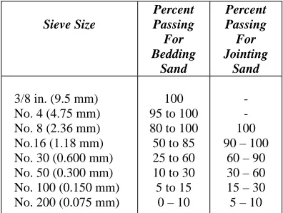
Sand: River sand from Kulai in Johor-Malaysia was used. The particle size distribution of bedding and jointing sand follow the grading requirement as tabulated in Table 1. Prior to use in each experiment, the sand was oven dried at 110°C for 24 h to maintain uniformity in test results. A maximum dry density of 1.73 gm/cc was obtained, corresponding to an optimum moisture content of 8.2 %. Two separate sand gradations were be used for the bedding layer and in the block joints.
Table 1. Grading requirements for bedding sand and jointing sand
BS 1377 Part I (1990) and TN 35: CCA (1996)
Paver: The concrete paving blocks conform to ASTM C 936, and 60 mm and 100 mm thickness, and rectangular in shape. Concrete blocks of 60 mm thickness and 110 x 220 mm of rectangular shape were used as the surface layer of the experiments. The mean compressive strength of the blocks was 32.30 MPa.
Test Set up
The horizontal force test was conducted using steel frame as edge restraint of 2.00 m wide and 2.00 m length. The test set up (shown in Fig. 2.) with construction varieties of CBP with laying pattern (stretcher bond, herringbone 90o and herringbone 45o) and joint width (3mm, 5 mm and 7mm). Loads were applied to the test pavement from side by using a hydraulic jacking system of 100 kN capacity clamped to the reaction steel frame.
Sieve Size
Percent Passing For Bedding
Sand
Percent Passing For Jointing
Sand
3/8 in. (9.5 mm) No. 4 (4.75 mm) No. 8 (2.36 mm) No.16 (1.18 mm) No. 30 (0.600 mm) No. 50 (0.300 mm) No. 100 (0.150 mm) No. 200 (0.075 mm)
100 95 to 100 80 to 100 50 to 85 25 to 60 10 to 30 5 to 15
0 – 10
- - 100 90 – 100
60 – 90 30 – 60 15 – 30 5 – 10
Paver Bedding Sand
Steel Frame
Figure 2. Horizontal Force Test Set up
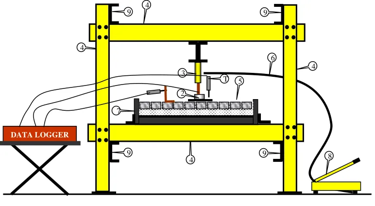
The push-in test was conducted using steel frame in a laboratory-scale model assembled for this purpose (Fig.3). The test set up was a modified form of that used by Shackel (1980), where the pavers were laid and compacted within a steel frame in isolation from the bedding sand, sub-base course, and other elements of CBP. Here, instead of a frame, the tests were conducted in a box to incorporate the elements of CBP (i.e.
bedding course, jointing sand and paver). It consists of a rigid steel box of 1000 x 1000 mm square in plan and 200 mm depth, in which pavement test sections were constructed. The box was placed on a steel plate 10 mm thickness, beneath the reaction frame. Loads were applied to the test pavement through a rigid steel plate using a hydraulic jacking system of 100 kN capacity clamped to the reaction frame.
Figure 3. Push-in test setup
1. Transducer 2. Load Cell 3. Hydraulic Jack
4. Steel Frame C Profile 5. Bedding Sand 6. Oil Pipe
7. Steel Frame Box 1mx1m 8. Hydraulic Pump 9. Cross Steel Frame DATA
LOGGER
Load cell Transducer
Paver
Jointing Sand
Pump
ConcreteFloor Bedding Sand
Steel Angle
4
4 4
6
8 4
9
9 9
3
T
2
9 7
5
3. Construction of Test Sections
The test sections of CBP were constructed within the box. A steel plate of 12 mm thick covered with sand was supported by steel frame (I beam profile). This thickness is reasonable for use in CBP to prevent immediate shear failure along the joints between blocks. At any two adjacent edges of the test pavement, side steel plates of required thickness were placed to control the desired width of joints in each test. The length and depth of side plates were 1000 and 200 mm, respectively. The depth was selected such that the side plates, when placed on the base, would reach the top of the block layer. Bedding sand of a particular gradation and thickness as per test requirements was uniformly screeded to a loose state. Pavers were then manually placed on the bedding sand in stretcher bond. Once the pavers were placed, they were compacted by a vibrating plate compactor of 250 N static weights vibrating at a frequency of 3,000 rpm. The compaction was continued until the top of each paving block was level with the adjacent blocks and to refusal of further settlement under vibration. The joints were then filled by brushing in the jointing sand. The joint filling operation was continued until all joints were completely filled with sand. Finally the top surface of pavement was cleaned of excess sand.
4. Test Procedures
A hydraulic jack fitted to the reaction frame applied a central load to the pavement through a rigid circular plate with a diameter of 300 mm. This diameter corresponds to the tire contact area of a single wheel, normally used in pavement analysis and design. A maximum load of 51 kN was applied to the pavement. The load of 51 kN corresponds to half the single axle legal limit. Deflections of the pavements were measured using four transducers to an accuracy of 0.01 mm corresponding to a load of 51 kN. The transducers were placed on two opposite sides of the plate at a distance of 100 mm from the center of the loading plate. The average value of four deflection readings was used for comparing experimental results.
The parameters, including joint width, thickness of bedding sand, and thickness of paver, were varied in the experimental program. For each variation of a parameter, the test was repeated three times to check the consistency of
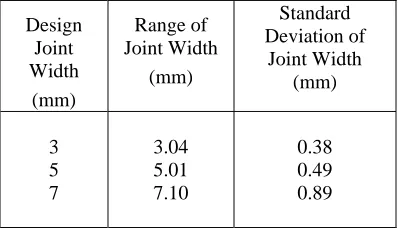
readings. The average of the three readings is presented in the experimental results in graphical form. The range of the standard deviations (SD) of the readings for each parameter is presented in the respective figures. For each test, measurements of joint width were made at 20 randomly selected locations. The mean and standard deviation were calculated to assess the deviation from the design joint width. Design joint width as referred to herein be the desired width established in the experiment; however, the achieved joint widths always varied. The mean and standard deviation of joint widths description with and without sand before compacted are summarized in Table 2. While discussing experimental results, pavement deflections were compared referring to design joint widths.
Table 2. Width joint description with sand
Design Joint Width
(mm)
Range of Joint Width
(mm)
Standard Deviation of
Joint Width (mm)
3 5 7
3.04 5.01 7.10
0.38 0.49 0.89
5. Results and Discussions
0 1 2 3 4 5 6 7
3 mm 5 mm 7 mm
Joint width
D
ispl
acement
(
m
m
)
With sand Without sand
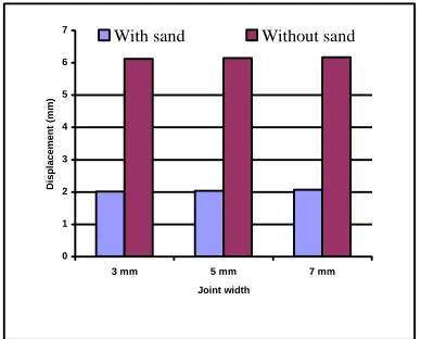
Figure 4. Pavement deflection with and without sand in joints
5.1. The Effect of Joint Width
The width of joints in block paving is more important than perhaps that has been realized in the past. A serious disadvantage of pavements laid in this way is that joints of less than 2 mm in width often contain little of no jointing sand. This would obviously reduce the contribution of individual blocks to the structural properties of the pavement. The individual blocks move in relation to one another which results in the spelling of the edges.
Sand filled joints are an integral part of concrete block pavement. They permit the block surface course to behave flexibly by allowing some articulation of individual blocks and they provide the structural interlock necessary for stresses to be distributed among adjacent blocks. Joints need to be sufficiently wide to allow this flexible behaviour, but not so wide as to permit excessive movement of the pavers. Joint widths should lay in the range of 2 to 7 mm with a preferred size of 3 mm. Those wider than 5 mm should not be accepted. 2 mm wider spacer ribs cast integrally on the vertical surfaces of the pavers ensure minimum joint width and assist in rapid placement of the blocks
The sand was used in bedding course with a 50 mm thickness for all of these experiments. Figure 5 shows the response of pavement for design joint widths of 2 mm, 3 mm, 5 mm, 7 mm and 9 mm with the same quality of sand. As the joint width decreases, the deflection of the pavement also decreases. The deflection of pavement decreases up to a certain point and then slightly increases with decrease in joint width, i.e., there is an optimal joint width.
The optimum joint widths for these experiments are 3 mm, respectively.
0.0 0.5 1.0 1.5 2.0 2.5 3.0 3.5 4.0
0.0 1.0 2.0 3.0 4.0 5.0 6.0 7.0 8.0 9.0 10.0
Design of joint w idth (mm)
D
e
fle
c
tio
n
(
mm
)
Figure 5. The response of pavement deflection for design joint widths
For joint widths less than the optimum, in a slight increase in deflections was observed. Some of the grains coarser than the joint width were unable to enter inside. This has been observed during filling sand in joints. A large amount of sand remained outside the joint showing sand heaps on the block surface. The coarse grains of sand choke the top surface of joints and prevent movement of other fine grains in to the joint. There might be loose pockets or honeycombing inside the joint. The joint stiffness decreases and in turn gives slightly higher deflections.
5.2. Filling of Jointing Sand
Figure 6. The bedding sand rises through the joints to small heights and wedges in between the blocks
Consequently, some compaction of bedding sand takes place under load and thus shows more deflection in the test pavements. The higher the bedding sand thickness, the more the deflection will be.
0 5 10 15 20 25
30 mm 50 mm 70 mm
Bedding sand thickness (mm)
San
d
ri
ses
b
e
tween
bloc
k
s
(
m
m
)
3 mm joint width 5 mm joint width 7 mm joint width
Figure 7. The comparison for bedding sand which rises in various widths joint and bedding sand thickness
The findings of this study are contradictory to those reported by Knapton and O’Grady (1983). They have found an increase in bedding sand thickness produced a proportionate increase in load-carrying capacity of pavement. As the pavement response is nearly for 50 mm thickness of bedding sand, it can be recommended for use in the field. But this depends on other factors, such as required level in sub-base tolerance and rise of bedding sand through the joints. Also, there should be a sufficient depth of bedding sand for deflection of pavements under load. Rise of bedding sand is essential to induce interlock.
The results show that the decrease in joint width increases the pavement performance and the concept of optimum joint width agrees well with that of a series of static load tests.
The bedding sand rises through the joints to small heights and wedges in between the blocks
6. Conclusion
Based on the test results obtained in this investigation, the following conclusions can be drawn:
• In general, the coarser the sand the higher will be the dilatancy and angle of shearing resistance.
• Coarse-grained sand with a greater shearing resistance and a loose thickness of about 50 mm should be used in the bedding course of concrete block pavements. The maximum size of the jointing sand should be less than the joint width, and the sand should contain a small amount of fines (passing the 75µm sieve).
• The joints in between blocks should be properly filled with sand. The optimum joint width between blocks is 3 mm. For joint widths less than the optimum, the jointing sand was unable to enter inside between blocks. A large amount of sand remained outside the joint showing sand heaps on the block surface.
References:
ASTM. (1972). Standard test methods for direct shear tests of soils under consolidated
drained condition. D 3080-72, West
Conshohocken, Pa.
British Standards. (1973). Specification for aggregates from natural sources for concrete. BS 882, 1201: Part 2, London.
Casagrande, A. (1940). Characteristics of cohesionless soils affecting stability of slopes and earth fills. Contributions to soil mechanics 1925–1940, Boston Society of Civil Engineers, Boston, 257–276.
Goodman, R. E., and Dubois, J. (1972). Duplication of dilatancy in analysis of jointed rocks J. Soil Mech. and Found. Div., ASCE, 98(4), 399–422.
Paver
B
C
A
Beddin g Sand
Knapton, J., and O’Grady, M. (1983). Structural Behavior of Concrete Block Paving. Journal Concrete Society: 17–18.
Lee, K. L., and Seed, B. H. (1967). Drained strength characteristics of sands. J. Soil Mech. and Found. Div., ASCE, 93(6), 117– 141.
Rowe, P. W. (1962). The stress dilatancy relations for state equilibrium of an assembly of particle in contact Proc., Royal Soc. of London, Series A, Vol. 269, London, 500–527.
Shackel, B. (1980). The performance of interlocking block pavements under accelerated trafficking. Proc., 1st Int. Conf. on Concrete Block Paving, Newcastle-upon-Tyne, U.K., 113–120.
Shackel, B. (1985). Evaluation, design and application of concrete block pavements.
Proc., 3rd Int. Conf. on Concrete Pavement
Design and Rehabilitation, Purdue
University, West Lafayette, Ind., 113–125.
Shackel, B., and Lim, D. O. O. (2003).