MULTI-OPTIMIZATION OF PID CONTROLLER PARAMETERS USING STOCHASTIC SEARCH TECHNIQUES FOR
ROTARY INVERTED PENDULUM SYSTEM
ELHAM YAZDANI BEJARBANEH
A project report submitted in fulfilment of the
requirements for the award of the degree of
Master of Engineering (Electrical- Mechatronic and Automatic Control)
Faculty of Electrical Engineering
Universiti Teknologi Malaysia
ACKNOWLEDGMENT
First of all, gratefulness of thanks to our creator, “ALLAH” for his
continuous blessing, which make this work neither the first nor the last.
Special thanks go to Dr. Salinda Buyamin for her encouragement, guidance, comments and advices during the duration of my master project. Without my supervisor’s support and interest, this report would not have been the same as present
here.
I would like to appreciate to all my friends and others who have provided assistant at various occasions. Their views and tips are very useful indeed. Unfortunately, it is not possible to list all of them in this limited space.
ABSTRACT
ABSTRAK
TABLE OF CONTENS
CHAPTER TITLE PAGE
DECLARATION ii
DEDICATION iii
ACKNOWLEDMENT iv
ABSTRACT v
ABSTRAK vi
TABLE OF CONTENTS vii
LIST OF TABLES x
LIST OF FIGURES xi
LIST OF ABBREVIATIONS xiii
LIST OF SYMBOL xiv
LIST OF APPENDICES xv
1 INTRODUCTION 1 1.1 Introduction 1
1.2 Overview 1 1.3 Rotational Inverted Pendulum System 2 1.3.1 Description of Rotary Inverted Pendulum 4
1.4 PID controller 5
1.4.1 The characteristic of P, I and D controllers 6
1.5. Model Reference Adaptive System 7
1.6.1 Particle Swarm Optimization algorithm 8
1.6.1.1 Constriction coefficient of PSO 9
1.6.2 Differential Evolution algorithm 10
1.6.2.1 Mutation 11
1.6.2.2 Crossover 11
1.6.2.3 Selection 12
1.7 The importance of study 12
1.8 Problem statement 12
1.9 Objective of project 13
1.0 Scope 13
1.11 Summary of chapter 14
2 LITERATURE REVIEW 15 2.1 Introduction 15
2.2 Types of Inverted Pendulum System 15
2.2.1 Inverted Pendulum System 15 2.2.2 Rotary Inverted Pendulum System 16
2.3 Types of controller design 17 2.4 Types of random search methods and algorithms 18 2.4.1 Optimization criteria 19
2.5 Summary of chapter 20
3 RESEARCH METHODOLOGY 21 3.1 Mathematical modeling of RIP system 22 3.1.1 Modeling technique 24
3.2 Nonlinear model of RIP system 28
3.3. Linear model by a linearization process 30
3.4 RIP realization 32
3.4.1 RIP realization in s domain 34
3.5 Controller design 35
3.5.1 PID controller 35
3.5.1.1 The Ziegler and Nichols method 35
3.5.2 MRAC-PID controller 38
3.5.2.2 Reference model design 39 3.5.2.3 Adaptive mechanism design 39
3.6 Stochastic algorithm design 42
3.6.1 PSO method/algorithm understanding and design 42 3.6.1.1 CPSO algorithm understanding and design 43 3.6.2 DE method/algorithm understanding and design 47
3.7 Summary of chapter 50
4 SIMULATION RESULTS AND DISSCUSION 51
4.1 Introduction 51
4.2 Simulation result without controller 51 4.3 Simulation result with MRAC-PID controller 54 4.3.1 Analyze output response for gain adjustment of 56 MRAC controller design
4.4 Simulation result with stochastic algorithms 57
4.4.1 Convergence curve 58
4.4.2 Performance 61
4.5 Discussion and comparison between different methods 63
based on servo behavior
4.6 Discussion and comparison between stochastic techniques 65 (pendulum’sangle)
4.7 Discussion and comparison between stochastic techniques 66
(arm’sangle)
4.8 Analysis of results 68
4.9 Summary of chapter 68
5 CONCLUSION AND RECOMMENDATION 69
FOR FUTURE WORK
5.1 Conclusion 69
5.2 Recommendation for future work 70
REFERENCES 71
LIST OF TABLES
TABLE NO. TITLE PAGE 1.1 Effect of PID gain on a closed loop system 6
2.1 Effectiveness of optimization criteria 20
3.1 The Description of RIP Parameters 23
3.2 The numerical value of system parameters 33
4.1 Comparison of performance PID controller 55 between Ziegler and Nichols method and
MRAC-PID Controller
4.2 Range of three PID controller parameters 58
4.3 Tuned PID gainofPendulum’sanglefrom 60
different Stochastic methods
4.4 TunedPIDgainofArm’sanglefrom 60
different Stochastic methods
4.5 Best Result of PID performance by using 66
PSO, CPS DE and MRAC methods (Pendulum)
4.6 Best Result of PID performance by using 67
LIST OF FIGURES
FIGURE NO. TITLE PAGE
1.1 Types of Inverted Pendulum 3
1.2 Pendulum rides 3
1.3 Crane machine 4
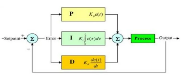
1.4 Rotary Inverted Pendulum 5 1.5 Block diagram of PID Controller 5
2.1 Inverted Pendulumlodel 61 2.2 Rotary Inverted Pendulum Model 17 3.1 Research Methodology Flowchart 22
3.2 A model of Rotary Inverted Pendulum 23
3.3 Nonlinear model of RIP system by Simulink 30
3.4 linear model of RIP system by Simulink 31
3.5 RIP transfer function block 35
3.6 Determining of Ziegler and Nichols 36 3.7 Diagram of Ziegler & Nichols-PID Controller 37 3.8 General structure of MRAC block diagram 38
3.9 Block diagram of MRAC –PID Controller 41
3.10 Particle new position 43
3.11 Block diagram of PSO-PID Controller 44
3.12 Flowchart of simple PSO algorithm 45
3.13 Flowchart of PSO-PID algorithm 46
3.15 Flowchart of simple DE algorithm 48
3.16 Flowchart of DE-PID algorithm 50
4.1 Step response of angular displacement 52
of pendulum(Nonlinear model)
4.2 Step response of angular displacement 52
of arm(Nonlinear model)
4.3 Step response of angular displacement 53
of pendulum(linear model)
4.4 Step response of angular displacement 53
of arm(linear model)
4.5 Step response of typical RIP system with 54 Ziegler and Nichols-PID controller
4.6 Step response of typical RIP system with 55 MRAC-PID Controller
4.7 Output response for different adaptive gains 56
4.8 Simulink design of stochastic algorithms 57
4.9 Convergence tendency of PSO-PID Controller 58
4.10 Convergence tendency of CPSO-PID 59
4.11 Convergence tendency of DE-PID Controller 59
4.12 The pendulum angle and arm angle 61 using PSO based PID controller
4.13 The pendulum angle and arm angle 62 using CPSO based PID Controller
4.14 The pendulum angle and arm angle 62 using DE based PID Controller
4.15 Comparative result of Intelligent Techniques 64
LIST OF ABBREVIATIONS
- Direct current
PID - Proportional Integral Derivative MATLAB - Matrix Laboratory Software
- Model Reference Adaptive Control
- Pulse Width Modulator - Integral absolute error
- Integral Time Absolute error - Integral Square Error
- Integral Time Square Error PSO - Particle Swarm Optimization
LIST OF SYMBOL
- Length of actuating link
- Length of pendulum link - DC motor inertia
- Mass of actuating motor
- Mass of pendulum link - Inertia of actuating link
- Pendulum link Inertia - Gravity coefficient
- Distance to center of gravity of pendulum link - Distance to center of gravity of actuating link
- DC motor armature resistance - Torque transmission coefficient - Back-EMF coefficient - Angular displacement of actuating link (arm)
̇ - Angular velocity of actuating link (arm)
- Angular displacement of pendulum link
LIST OF APPENDICES
APPENDIX TITLE PAGE
A RIP nonlinear model in Simulink block 76
B m code of converting state space equation to 78
Transfer function
CHAPTER 1
INTRODUCTION
1.1 Introduction
This chapter covers the Rotational Inverted Pendulum system (RIP), Proportional-Integral-Derivative (PID) controller, Model Reference Adaptive System (MRAS), Particle Swarm Optimization (PSO), Constriction Coefficient method of PSO algorithm (CPSO) and Differential Evolution (DE) algorithm. The motivation of applying PSO, CPSO and DE as an optimization algorithms is also considered in this chapter.
1.2 Overview
During the past decades, numerous modern control methodologies have been introduced and applied for control approaches and industrial application [1-2] such as
nonlinear control [2-3], Linear Quadratic regulator [3-4], optimal control [5], Pole placement controller [6] and adaptive control combined with state feedback controller [5-7-9].
[8-10-12]. Unfortunately, it has been difficult to tune up PID parameters accurately
because of complexity of many industrial plants such as higher order, time delays, and nonlinearities [7, 9].
Ziegler and Nichols presented the simple method that is widespread as classical tuning rules [10]. Though, the determination of optimal PID controller parameters with Ziegler-Nichols formula [14] results in less optimal performance [9- 10].
To overcome these difficulties, over the past years, several evolutionary algorithms have been proposed to search for optimal PID controllers. In this project, the efficiency of two intelligent algorithms is compared, that are DE and PSO. These evolutionary algorithms are used to adjust the PID controller parameters [5] of the closed-loop system of RIP. For this purpose, the model proposed is Rotational Inverted Pendulum (RIP) system. The reason to choose this model is that this system is known as inherent nonlinear system which can be a good prospect for control engineering.
1.3 Rotational Inverted Pendulum
Rotary Inverted Pendulum system as shown in Figure 1.1 is a challenging problem in the area of control systems and this system is inherently unstable and nonlinear system [22]. It is a familiar system chosen for evaluation various control techniques [23],[15]. It has also some significant real life applications such as pointing control, aerospace vehicle control[19], robotics[1, 18, 19], control professionals[22],pendulum rides[24, 25], crane machine, rockets[19], robotic arm[1, 11,18], the flight simulation of rocket or missile[18] and other transportation means[2] and etc. Some example of real life applications of RIP system are shown in figure 1.2 and 1.3. Besides that, RIP is widely used as benchmark for testing control algorithms such as Proportional Integral Derivative (PID) controllers, neural networks,
bed for the controller design are because the system is a nonlinear system and easily
available for laboratory usage. Another advantage is it can be treated as a linear system
without much error compared to nonlinear model for a wide range of variation [2-18].
Figure 1.1: Rotary Inverted Pendulum model [18]
1.3.1 Description of Rotational Inverted Pendulum System
The rotary inverted pendulum consists of a rigid rod (pendulum) rotating in a vertical plane. The rigid rod is attached to an actuating link (arm) that is fixed on the shaft of the servo motor. The actuating link (arm) can be rotated horizontally by the servo motor, while the pendulum hangs downwards. A normal pendulum is considered stable when hanging downwards, while the rotary inverted pendulum is inherently unstable, and must be actively balanced for remaining upright, either by utilizing a torque at the pivot arm or by moving the pivot arm horizontally as part of a feedback system. A diagram of the RIP system is shown in Figure 1.4, where L1,
L2, M1, M2, are the length of arm, the pendulum length, the arm‟s mass, the
pendulum‟smass, the angular displacement of arm and the angular displacement of pendulum, respectively. The input of RIP system in this research is considered the torque of motor and the performance of angular displacement of pendulum and angular displacement of arm will be analyzed separately as the output of RIP system.
1.4 PID controller
A proportional–integral–derivative controller (PID controller) is the most common form of feedback controllers and widely is used in industrial control systems (see Fig 1.5). A PID controller calculates an “error”valueasthedifference between a desired set-point and a measured process variable. The controller signal ( attempts to minimize the error by adjusting the process inputs as follow:
∫ (1.1)
Figure 1.4: Diagram of Rotary Inverted Pendulum
1.4.1 The characteristic of P, I and D controllers
The transfer function of PID controller looks like the following:
+ + s = (1.2)
= Proportional gain
= Integral gain
= Derivative gain
A proportional gain ( ) will have the effect of reducing the rise time and will reduce the steady state error, but never eliminate, the steady-state error. An integral gain ( ) will have the effect of eliminating the steady-state error, but it may make the transient response worse.
A derivative gain ( ) will have the effect of increasing the stability of the system, reducing the overshoot, and improving the transient response. Effects of each of gains , , and on a closed-loop system are
summarized in the table shown below.
Table 1.1: Effect of PID gains on a closed-loop system [7]
Parameter Rise Time Overshoot Setting Time Steady State Error
Decrease Increase Small change Decrease
Decrease Increase Increase Eliminate
Note that these correlations may not be exactly accurate, because , , and
are dependent of each other. In fact, the table should only be used as a reference when you are determining the values for , and .
1.5 Model Reference Adaptive System
Adaptive system is defined by (Narendra and Annaswamy,1989) [5] as a system
which is provided with a means of continuously monitoring its own performance in
relation to a given figure of merit or optimal condition and a means of modifying its own
parameters by a closed loop action to approach a optimum condition. MRAS that uses
Model Reference Adaptive Control (MRAC) is an adaptive system that makes overt use
of such models for identification or control purposes. MRAC as adaptive controller is
chosen to control the RIP system based on the performance wise and other
characteristics. Tracing back chronologically from 1950s [5,7] until now, the automatic
control of physical processes has been an experimental technique deriving more from art
than from scientific bases. When implementing a high-performance control system, the
poor characteristic plant dynamic characteristics starts to arise. Besides that large and
unpredictable variations occur. As a result, a new class of control systems called
adaptive control systems has evolved which provides potential solutions. In the late 1950s,manysolutionshavebeenproposedinordertomakeacontrolsystem“adaptive”
and among of them is a special class of adaptive systems called Model Reference
Adaptive System.
1.6 Evolutionary & Stochastic Algorithms
Evolutionary Algorithms simulate the evolution of individual structures via processes of selection, mutation and recombination.
Stochastic optimization plays a significant role in the analysis, design, and
operation of modern systems. Methods for stochastic optimization provides a meant of coping with inherent system noise and coping with models or systems that are highly nonlinear, high dimensional, or otherwise inappropriate for classical deterministic methods of optimization. Algorithms that employ some form of stochastic optimization have been widely available as stochastic optimization algorithms and have broad application to problems in statistics, science, engineering, and business.
1.6.1 Particle Swarm Optimization Algorithm
PSO as popular optimization technique representatives of stochastic algorithms was introduced in 1997 by Eberhart and Kennedy [13]. PSO algorithm is considered as swarm intelligent algorithm because of self-organization and information communication between its particles and it is also a meta-heuristic algorithm because with few information of optimization problem is able to solve the problems. It is also applied to serves PID controller on plant associated with nonlinearities. The PSO algorithm is initialized with a population of random particles (birds). These particles have two essential capabilities: their memory of their own best position and knowledge of the global best. Members of a swarm communicate good positions to each other and adjust their own position and velocity based on good positions.
= ( , , ) = ( , , ) and = ( , , )
= + ( ) + ( j ) (1.3)
= = + (1.4)
Where
velocity of particle i and dimension j
position of particle i and dimension j
Learning factors and represent the cognition and social
components, respectively, which attract the particles to the local best and global best positions.
Inertia weight factor
Random numbers between 0 and 1
Best position of a specific particle
Best particle of the group
1.6.1.1 Constriction Coefficient of PSO
weight ω and the maximum velocity parameter . The velocity update scheme
proposed by Clerc can be expressed for the dth dimension of ith particle as:
χ[ ( )
(1.5)
Where,
χ=
√ with (1.6)
In order to initialize the parameters of PSO algorithm, CPSO method proposed a specific range for Inertia weight factor ( and acceleration factors ( of PSO algorithm as follow:
Where (1.7)
ConstrictioncoefficientFactor=χ= √ (1.8)
Where
, and (1.9)
1.6.2 Differential Evolution Algorithm
while DE relies on mutation operation. This main operation is based on the differences of randomly sampled pairs of solutions in the population.
The algorithm uses mutation operation as a search mechanism and selection operation to direct the search toward the prospective regions in the search space. The DE algorithm also uses a non-uniform crossover that can take more information to search for a better solution space.
The DE algorithm serves PID controller on nonlinear plant as task consisting of three parameters can be represented by a 3-dimensional vector. In DE, a population of NP solution vectors is randomly created at the start. This population is successfully improved by applying mutation, crossover and selection operators.
1.6.2.1 Mutation
For each target vector, a mutant vector is produced by
( ) (1.10)
Where I,,, (1,2,……,NP) are randomly chosen and must be different from each other. In equation (1.11) F is the scaling factor which has an effect on the difference vector, K is the combination factor.
1.6.2.2 Crossover
The parent vector is mixed with the mutated vector to produce a trial vector
{
Where j=1,2,…..,D; [ is the random number; CR is crossover constant [ and r is the randomly chosen index.
1.6.2.3 Selection
All solutions in the population have the equivalent chance of being selected as parents without dependence of their fitness value. The child produced after the mutation and crossover operations is evaluated. Then, the performance of the child vector and its parent is compared and the better one is selected. If the parent is still better, it is improved in the population.
{ ( ) ( )
(1.12)
1.7 The Importance of the study
The open loop rotary inverted pendulum is an inherent unstable system. The controller design shall improve the transient response, steady state error and stability
of system. This research mainly converts the uncompensated system to the compensated system. Then, it is to ensure whether the design of the PSO-PID and DE-PID controllers meet the desired output or not.
1.8 Problem identification/statement
(i) Rotary inverted Pendulum is inherently unstable system, which moves continually toward an uncontrolled state.
(ii)The problem of designing PID controllers as an optimization problem
conventional tuning may result poor performance specially for controlling a non-linear processes . The suggestion is trying to solve
with PSO & DE forbettersystem‟sperformance.
1.9 Objectives of project
(i) To applyLagrange‟sequationinordertoobtainmathematicalmodel of the rotary inverted pendulum system.
(ii) To tune of PID parameters automatically for RIP based on MRAC concept.
(iii) To tune PID controller parameters that is applied to RIP by utilizing stochastic algorithms such as PSO and DE algorithms.
(iv) To compare the performance of PID controller with proposed evolutionary approaches, which it is desired that these stochastic optimization algorithms to achieve superior quality of solution and performance.
1.10 Scope of project
For this work at the following steps should be done
(i) Achieving the nonlinear model of RIP system by using Lagrange method.
(ii) The project proposes standard PSO and DE algorithms and MRAC controller to tune the PID parameters.
(iv) Only control angular displacement of Pendulum and actuating link (arm) of RIP system.
(v) Enhancing the performance of RIP system by minimizing the overshoot, rise time, setting time and steady state.
1.11 Summary of Chapter
REFERENCES
1. Bishop, R.C.D.a.R.H., ed. Modern control systems. 1998, ed. 8. 1998: Addison Wesley Longman. 136-137.
2. Hussain, A.M.a.C.D.S., Robust Controller for Nonlinear & Unstable System:
Inverted Pendulum. Journal of Control & design Simulation, 2000. 55: p.
49-60.
3. H. N Iordanou, B.W.S., Experimental evaluation of the robustness of discrete
sliding mode control versus linear quadratic control. Journal of IEEE
Transactions on control systems technology 1997. 5: p. 245-260.
4. G. W. Van der Linder, P.F.L., Control of an experimental inverted pendulum with dry friction, in IEEE Control System Magazine. 1993. p. 44-50.
5. Liang, S.C.a.Y., PIID-like neural network nonlinear adaptive control for
uncertain multivariable motion control systems Journal OF IEEE
Transactions on Industrial Electronics 2009. 56: p. 3872-3879.
6. Ahmad M.N, N.S.W.a.O.J.H.S., Development of a Two-Wheeled Inverted
pendulum Student conference on research and development, 2007.
7. Visiolo, A., Tunning of PID controller with fuzzy logic Journal of IEEE Transactions on control systems technology, 2001.
8. Gaing, Z.L., a particle swarm optimization approach for optimum design of
PID controller in AVR system. Journal of IEEE Transactions on control
systems technology, 2004. 9: p. 384-391.
10. Ziegler, J.G., and N. B. Nichols, Optimum setting for automatic controllers. journal of Engineering, 1943: p. 433-444.
11. Muskinja, N.a.B.T., Swinging up and stabilization of a real Inverted
Pendulum. Ieee Transaction, 2006.
12. O. Togla Altinzon, A.E.Y., Gerhard Wilhelm Weber, Application Of Chaos
Embedded Particle Swarm optimization for PID Parameter Tuning. Journal
of Aeronautical Engineering and Mechanics, 2009.
13. Eberhart, J.K.a.R., Particle Swarm Optimization. Journal Of IEEE Transactions on control systems design: p. 1942-1945.
14. C. L. L. Lin, H.Y.J., N. C. shieh, GA-based multiobjective PID control for a
linear brushless DC motor. Journal of IEEE Transactions on control systems
technology, 2003(Mechatronics): p. 56-65.
15. Mobayen, I.H.a.S., PSO-Based Controller Design for Rotary Inverted
Pendulum System. Journal of Science, 2008.
16. Awtar, K.C.a.S., Inverted pendulum systems:Rotary and Arm-driven
amechatronic system design case study. Journal of Aeronautical Engineering
and Mechanics.
17. G. F. Franklin, J.D.P., and A. Emami-Naeini, Feedback Control of Dynamic Systems. 1994: p. 552.
18. Sultan, K., Analysis, design and Implementation Of Inverted Pendulum, Institue of industrial electronics Engineering: Karachi, Pakistan.
19. Golten, J., Verwer, A, ed. Control System Design and Simulation. ed. 1. 1991, Hill Book Company(UK): UK. 198-204.
20. Kuo, B., Automatic Control Systems. 1995: Prentic Hall, Englwood Cliffs. p. 265-268.
21. Medrano-Cersa, G.A., Robust computer control of an inverted pendulum, in
IEEE Control System Mgazine. 1999. p. 58-67.
22. Parnichkun, V.S.a.M., Real-Time Optimal Control Rotary Inverted
Pendulum. Journal of Applied Sciences, 2009.
24. Berg, H.W.J.V.d., Introduction to the control of an inverted pendulum setup. Conference of Control, 2003.
25. http://en.wikipedia.org/wiki/pendulum_ride.
26. Astrom, K.J.a.K.F., Swinging up a pendulum by Energy control, in paper
peresented at IFAC. 1996: San Francisco California. p. 1-6.
27. Mehad Muskinja, B.T., Adaptive state controller for inverted pendulum. journal of Control, 2010.
28. Husin, M.B., Modeling and controller design for rotary inverted pendulum. journal of Control, 2010.
29. Bens, C.a.Z.P., On the dynamics of the Furuta pendulum. Journal of Control, 2010.
30. Tan Kok Chye, T.C.S., Rotary Inverted pendulum. Journal of Control, 1998/99.
31. Gopal, L.J.N.a.M., control system engineering Journal of Control, 2006.
32. Ker-Wei, Y., Member, IEEE, Zhi-Liang, Huang, LQ Regulater Desoign
based on PSO. Conference of IEEE on systems and cybernetics, 2006.
33. veerasundram, K., Designing model reference adaptive control for inverted
pendulum system, in University Teknologi Malaysia. MAY 2011, UTM:
Skudai.
34. Basir, B.A.B., Control of Cart-BAll using State Feedback And Fuzzy Logic Controller, in University Teknologi Malaysia. 2007.
35. Dongyun wang, G.W., Rong Hu, Parameters Optimization of fuzzy controller
based on PSO. Internatinal Conference on intelligent system and engineering
2008.
36. Rubi, J.a.A., A swing up control problem for a self-erecting double inverted
pendulum. Journal of IEEE Transactions on control systems technology,
2002: p. 169-175.
37. Salinda Buyamin, A.H.Y.Y., Norhaliza Abdul Wahab, INTEGRAL TIME ABSOLUTE ERROR MINIMIZATION FOR PI CONTROLLER ON
STOCHASTIC SEARCH TECHNIQUES. Journal of teknologi and Sains, 2011(University Teknologi of Malaysia): p. 381-402.
38. Subramanian, R.B.a.S., Optimization of Three-phase Induction Motor Design
Using Simulated Annealing Algorithm. 2003(Electronic Power Components
and Systems): p. 947-956.
39. Zhou, G.a.J.B., Fuzzy logic-based PID auto-tuner design using simulated
anealing Journal Of IEEE Transactions on control systems design, March
1994: p. 67-72.
40. Haupt, R.L.a.S.E.H., practical genetic algorithms. 1998. p. 1942-1948.
41. Wong, C.C.a.C., C. C, A GA-Based Method for Constructing fuzzy systems
directly from Numerical data. IEEE Transactions on Systems, Man and
Cybernetics, 2000: p. 904-911.
42. Wong, C.C.a.L., B. C, Lee, S. A and Tsai, C, H, GA-Based fuzzy system design in FPG for an omni-directional mobile robot. Journal og Intelligent & Robatics systems, 2005: p. 327-347.
43. Rahmat-Samii, Y., Genetic Algorithm (GA) and Particle Swarm Optimization
(PSO) in engieering electromagnetics. Internatinal Conference on
electromagnetics and communication October 2003.
44. Jones, B.P.a.A.H., Genetic tuning of digital PID control, Electronics Letters. 1992. 28: p. 834-844.
45. Kwok, D.P.a.S., F, Geneetic algorithm and Simulated Annealing for Optimal
Robot Arm PID control. Journal of IEEE Transactions on Evolutionary
Computation, 1994: p. 707-712.
46. Lin, C.O.a.W., Comparison between PSO and GA for Parameters
Optimization of PID controller. Internatinal Conference on Mechatronics and
Automation, 2006.
47. Hou, Z.S.L.a.Z.R., Particla swarm optimization. conference of IEEE on Neural network, 2004: p. 1942-1948.
48. Jixin Qian, Liyan Zhang, Longhua Ma and Yongling Zheng Robust PID
49. Swagatam Das1, Ajith Abraham2, and Amit Konar1, Particle Swarm Optimization and Differential Evolution Algorithms: Technical Analysis,
Applications and Hybridization Perspectives, 2006: p. 1942-1948.
50. Dervi’s KARABOGA, Selcuk ¨OKDEM, A Simple and Global Optimization
Algorithm for Engineering Problems: Differential Evolution Algorithm, 2004:
![Figure 1.1: Rotary Inverted Pendulum model [18]](https://thumb-us.123doks.com/thumbv2/123dok_us/1332873.1166252/17.595.202.472.421.649/figure-rotary-inverted-pendulum-model.webp)