University of Windsor University of Windsor
Scholarship at UWindsor
Scholarship at UWindsor
Electronic Theses and Dissertations Theses, Dissertations, and Major Papers
2014
Effect of Roll Material on Surface Quality of Rolled Aluminum
Effect of Roll Material on Surface Quality of Rolled Aluminum
Qi Zhao
University of Windsor
Follow this and additional works at: https://scholar.uwindsor.ca/etd
Part of the Materials Science and Engineering Commons
Recommended Citation Recommended Citation
Zhao, Qi, "Effect of Roll Material on Surface Quality of Rolled Aluminum" (2014). Electronic Theses and Dissertations. 5080.
https://scholar.uwindsor.ca/etd/5080
This online database contains the full-text of PhD dissertations and Masters’ theses of University of Windsor students from 1954 forward. These documents are made available for personal study and research purposes only, in accordance with the Canadian Copyright Act and the Creative Commons license—CC BY-NC-ND (Attribution, Non-Commercial, No Derivative Works). Under this license, works must always be attributed to the copyright holder (original author), cannot be used for any commercial purposes, and may not be altered. Any other use would require the permission of the copyright holder. Students may inquire about withdrawing their dissertation and/or thesis from this database. For additional inquiries, please contact the repository administrator via email
Effect of Roll Material on Surface Quality of Rolled Aluminum
by
Qi Zhao
A Thesis
Submitted to the Faculty of Graduate Studies through Engineering Materials
in Partial Fulfillment of the Requirements for the Degree of Master of Applied Science at the
University of Windsor
Windsor, Ontario, Canada
2014
Effect of Roll Material on Surface Quality of Rolled Aluminum
by
Qi Zhao
APPROVED BY:
______________________________________________ A. T. Alpas
Mechanical, Automotive, and Materials Engineering
______________________________________________ S. Chowdhury
Electrical and Computer Engineering
______________________________________________ A.R. Riahi, Advisor
Mechanical, Automotive, and Materials Engineering
III
DECLARATION OF ORIGINALITY
I hereby certify that I am the sole author of this thesis and that no part of this thesis has
been published or submitted for publication.
I certify that, to the best of my knowledge, my thesis does not infringe upon anyone’s
copyright nor violate any proprietary rights and that any ideas, techniques, quotations, or any
other material from the work of other people included in my thesis, published or otherwise, are
fully acknowledged in accordance with the standard referencing practices. Furthermore, to the
extent that I have included copyrighted material that surpasses the bounds of fair dealing within
the meaning of the Canada Copyright Act, I certify that I have obtained a written permission
from the copyright owner(s) to include such material(s) in my thesis and have included copies of
such copyright clearances to my appendix.
I declare that this is a true copy of my thesis, including any final revisions, as approved
by my thesis committee and the Graduate Studies office, and that this thesis has not been
IV
ABSTRACT
The surface defects of aluminum alloys that have undergone hot rolling were studied.
The effects of different roll materials, of the number of rolling passes and of lubrication
on surface defects of hot rolled aluminum alloys were investigated by laboratory hot rolling.
Two different aluminum alloys, Al-Mn and Al-Mg, were each rolled against three different steel
alloy rolls, AISI 52100, AISI 440C and AISI D2. The results showed that different roll materials
do affect the morphology of the mating aluminum alloy surface with apparent surface defects,
which included magnesium and oxygen rich dark regions on both alloys. The carbide protrusions
in 440C and D2 steel rolls are confirmed to be responsible for the dark, rich magnesium and
oxygen regions on both the rolled Al-Mn and Al-Mg alloy surfaces. As the number of passes
V
DEDICATION
To my parents;
Without my loving parents unconditional love, support, and encouragement, I wouldn't have
been able to continue my study.
I dedicate my dissertation work to my advisor Dr. A Riahi. He is my respected advisor for my
academic career.
I also dedicate my dissertation work to my colleague Olufisayo Gali, without his help I would be
VI
ACKNOWLEDGEMENTS
I would like to give my sincere gratitude to Dr. Riahi; without his support and
encouragement, I wouldn't have finished my research work. His mentorship and knowledge have
been a great help to my career. I would also like to thank Dr. Alpas for his continual support, and
his valuable suggestions have indeed been an inspiration to my study. My thanks to Dr. Hunter
and Dr. Shafiei from Novelis Global Research and Technology Center, as well for their
comments, support and vital suggestions during this work.
I would like to express my gratitude to Dr. Chowdhury, giving thanks for his time and his
constant suggestions and inspiration to me. My thanks also to Dr. Northwood for his time and aid
on my final defence as well as my dissertation.
My special thanks to Olufisayo Gali for training me on the experiments, for valuable
suggestions and for inspiring ideas in my work. I would also like to thank the members of the
whole tribology group. They were always kind to provide equipment and guidance during my
research.
Financial support for this research is provided by Ontario Centers of Excellence
(OCE),Natural Sciences and Engineering Research Council of Canada (NSERC) and Novelis
VII
TABLE OF CONTENTS
DECLARATION OF ORIGINALITY ... III
ABSTRACT ... IV
DEDICATION... V
ACKNOWLEDGEMENTS ... VI
LIST OF FIGURES ... IX
LIST OF TABLES ... XV
NOMENCLATURE ... XVI
CHAPTER 1 INTRODUCTION ... 1
1.1 Background ... 1
1.1.1 Aluminum alloys ... 1
1.1.2 Heat-treatable and non-heat-treatable alloys ... 1
1.1.3 Rolling process ... 4
1.1.4 Steel roller alloys ... 6
1.2 Thesis objective ... 7
1.3 Organization of thesis ... 8
CHAPTER 2 REVIEW OF LITERATURE ... 10
2.1 Introduction of disturbed layer ... 10
2.2 Microstructure of the disturbed layer... 12
2.3 Content distribution in disturbed layer of aluminum alloy under rolling ... 15
2.4 Mechanisms of disturbed layer formation ... 22
2.5 Optical appearance ... 26
2.6 Effect of disturbed layer to filiform corrosion (FFC) ... 27
2.7 Rolling parameters that affect the surface layer ... 32
2.7.1 Heat treatment and strain effect ... 33
2.7.2 Material transfer and adhesion ... 36
2.7.3 Grinding effect ... 39
VIII
CHAPTER 3 DESIGN AND METHDOLOGY ... 41
3.1 The workpiece ... 41
3.2 The roller ... 41
3.3 Laboratory simulation ... 42
CHAPTER 4 RESULTS ... 46
4.1 Results with Al-Mn alloy ... 46
4.2 Results with Al-Mg alloy ... 48
CHAPTER 5 DISCUSSION... 74
CHAPTER 6 CONCLUSION ... 79
REFERRENCES ... 80
IX
LIST OF FIGURES
Figure 1. Optical micrographs of the two alloys a) AA3104, b) AA5182, c) Phase diagram of
binary Al–Mg system, d) Phase diagram of binary Al–Mn system [11,14] ... 4
Figure 2. Typical process route for can body stock [15,16] ... 5
Figure 3. Schematic representation of subsurface layer containing microcrystalline oxides mixed
with small grained material and covered with a continuous surface oxide. Layer A represents the
surface oxide layer and layer B represents the subsurface ultrafine grained layer [28] ... 13
Figure 4. SEM backscattered micrograph of the surface of Aluminum alloy AA5050: (a) as-cast;
(b) hot roll after first pass. [16] ... 14
Figure 5. Schematic diagrams showing the microstructure of near-surface deformed layer
introduced by rolling: (a) type A is hot rolling involved and (b) type B under cold rolling without
hot rolling involved [27] ... 15
Figure 6. Quantitative r.f. GDOES depth profile of hot rolled AA1050 [39] ... 17
Figure 7. a) Metallic element distribution as a wt% amount of the total metal content in the
subsurface layer of the laboratory rolled sample of aluminium alloy AA3104 [1]. b) Distribution
of Mg in the surface layer of aluminium alloy AA3104 measured for only reheated and reheated
followed by laboratory rolled specimens [42] ... 18
Figure 8. a) FIB image of AA3104 surface hot rolled in 1 pass at 753 K and with forward speed
12%; b) EDS analysis from the area marked as "d" in image a; the elements Pt and Ga are from
the protective coating and the ion source respectively; and c) EDS analysis from the area marked
as "e" (bulk material) in image a; d) evolution of AA3104 surface hot rolled in 2 passes in the
same direction, temperature and forward speed; e) EDS analysis of the area marked as "d" in
X
Figure 9. (a) GDOES depth profile analysis from the surface of an as-polished sample; (b)
GDOES depth profile analysis from the surface of a sample polished and heated to 753 K for
840s [29] ... 20
Figure 10. Image showing material transferred from the stock surface to the work roll surface
after the two-pass rolling on the Robertson mill [15] ... 21
Figure 11. Schematic representation of the roll-bite. Cross-sectional TEM analysis was carried
out along the planes A (just before entry), B (just after entry), C (neutral plane) and D (just after
exit) [41]... 23
Figure 12. AA3104 surface hot rolled in 1 pass at 753K and with 12% forward speed; (a)
localized shear deformations in the form of shingles; the inserted image magnifies the area in the
bracket; (b) low magnification image of the trench after FIB milling; the surface was platinum
coated first in order to avoid damage due to exposure to ion beam; (c) cracks formed beneath and
parallel to the surface [29] ... 24
Figure 13. Schematic of the influence of rolled-in oxides on the Total Reflectance (TR) [41,50]
... 27
Figure 14. Schematic view of a filiform filament on aluminum [56] ... 28
Figure 15 Effects of intermetallic particles on the propagation behavior of filiform filaments [56]
... 29
Figure 16. Surface-active filiform corrosion (left side figure): (a) SEM of cross-section show the
initial stages of filiform corrosion with attack of grain boundaries in the deformed layer; (b)
TEM showing the dispersoids (indicated by the arrows) in the corrosion product. SEM of
XI
boundary of the aluminum matrix after the near-surface deformed layer has been consumed; (d)
corrosion growth into one of the grains [33] ... 31
Figure 17. Optical micrographs of the 6082 alloy after homogenization: (a) rapidly-heated
specimen; (b) slowly-heated specimen. PFZ stands for precipitate free zones [40] ... 34
Figure 18. RF GDOES qualitative depth profiles of a hot-rolled AA3005 aluminum alloy: (a) "as
received"; (b) after annealing for 2 h at 500 °C [63] ... 35
Figure 19. Friction coefficient for polished samples; solid curves for tests with Somentor 32 base
oil, dashed curves for Somentor 32 plus a boundary additive [68] ... 39
Figure 20. General view and schematic of experimental setup of hot rolling simulation ... 44
Figure 21. a) WYKO images of surface profilometry of AISI 440C, D2 and 52100 steel rolls
(as-polished), surface roughness of 440C Ra = 0.0148, D2 Ra = 0.0108, 52100 Ra = 0.0089, b)
Micro graphs of 52100, c)440C, and d) D2 ... 50
Figure 22. WYKO images of surface profilometry of Al-Mn alloy after rolled 1 pass with AISI
440C, D2 and 52100 steel rolls, rolled with 440C Ra = 0.285, D2 Ra= 0.303, 52100 Ra = 0.286,
pits are observed covering the surface of the Al-Mn alloy after deformation with 440C and D2,
but not with 52100 ... 51
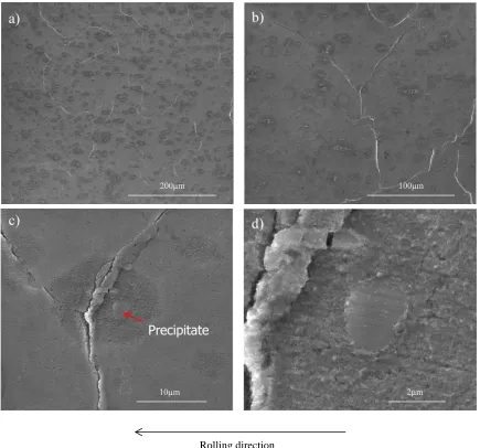
Figure 23. The SEM images of Al-Mn alloy rolled with 440C roll after 1 pass, order of
magnification from low to high for a) to d) ... 52
Figure 24. The SEM images of Al-Mn alloy rolled with D2 roll after 1 pass, order of
magnification from low to high for a) to d) ... 53
Figure 25. The SEM images of Al-Mn alloy rolled with 52100 roll after 1 pass, order of
XII
Figure 26. Comparison of the SEM images of Al-Mn alloy rolled with 440C, D2 and 52100, a)
and B) for rolled with 440C, c) and d) rolled with D2, e) and f) rolled with 52100 ... 55
Figure 27. The SEM images of a) and b) for 440C steel alloy surface after rolled with Al-Mn
alloy after 1 pass, c) and d) for D2 steel alloy surface after rolled with Al-Mn alloy after 1 pass, e)
and f) for 52100 steel alloy surface after rolled with Al-Mn alloy after 1 pass ... 56
Figure 28. The comparison of a) 440C, b) D2 and c) 52100 steel alloy surface after rolled with
Al-Mn alloy after 1 pass ... 57
Figure 29. EDS mapping of 440C steel alloy surface after rolled with Al-Mn alloy after 1 pass 57
Figure 30. EDS mapping of D2 steel alloy surface after rolled with Al-Mn alloy after 1 pass .... 58
Figure 31. EDS mapping of 52100 steel alloy surface after rolled with Al-Mn alloy after 1 pass
... 58
Figure 32. Comparison of EDS mapping of D2 and 440C steel alloy surface after rolled with
Al-Mn alloy after 1 pass with elements of O, Cr and V ... 59
Figure 33. SEM images of Al-Mg alloy surface rolled with 52100 steel roll after 1 pass, order of
magnification from low to high for a) to d) ... 60
Figure 34. SEM images of Al-Mg alloy surface rolled with 440C steel roll after 1 pass, a) SEM
image taken at 12 kV and b) SEM image taken at 5 kV, f) and h) are EDS analysis on surface
features at e) and g), respectively ... 61
Figure 35. SEM images of 440C steel alloy surface after rolled with Al-Mg alloy after 1 pass .. 62
Figure 36. EDS mapping of 440C steel alloy surface after rolled with Al-Mg alloy after 1 pass 63
Figure 37. SEM images of Al-Mg alloy surface rolled with 440C steel roll after 1 pass and 4
passes, a) and b) after 1 pass, c) and d) after 4 passes, magnification from low to high: 1 pass for
XIII
Figure 38. SEM images of Al-Mg alloy surface rolled with D2 steel roll after 1 pass and 4 passes,
a) and b) after 1 pass, c) and d) after 4 passes, magnification from low to high: 1 pass for a) to b)
and 4 passes for c) to d) ... 65
Figure 39. SEM images of Al-Mg alloy surface rolled with 52100 steel roll after 1 pass and 4
passes, a), b) and c) after 1 pass, d), e) and f) after 4 passes, magnification from low to high: 1
pass for a) to c) and 4 passes for d) to f) ... 66
Figure 40. EDS analysis of Al-Mg alloy surface features rolled with 440C steel roll after 4 passes,
a) at normal rolled surface region, b) at darkened grain boundary region, c) at dark patch area . 67
Figure 41. EDS analysis of Al-Mg alloy surface features rolled with D2 steel roll after 4 passes, a)
at normal rolled surface region, b) at darkened grain boundary region ... 67
Figure 42. EDS analysis of Al-Mg alloy surface features rolled with 52100 steel roll after 4
passes, a) at darkened grain boundary, b) at normal rolled surface region ... 68
Figure 43. WYKO images of surface profilometry of Al-Mg alloy after rolled a) 1 pass at 550 ºC
Ra = 0.206, b) 2 passes at 525 ºC Ra = 0.132, c) 3 passes at 500 ºC Ra = 0.196, d) 4 passes at
475 ºC Ra = 0.186, all with 440C, e) 5 passes at 475 ºC Ra = 0.198, all with 440C, and f) 6
passes at 475 ºC Ra = 0.203, all with 440C ... 69
Figure 44 SEM images of Al-Mg alloy surface rolled with 440C steel roll after 1 pass, 2 passes,
3 passes and 4 passes, a), b) and c) after 1 pass, d), e) and f) after 2 passes, g), h) and i) after 3
passes , j), k) and l) after 4 passes. Magnification from low to high: 1 pass for a) to c), 2 passes
for d) to f), 3 passes for g) to i) and 4 passes for j) to l) ... 70
Figure 45. Different conditions of lubrication a) nozzle close to roll, b) nozzle far from roll ... 71
Figure 46. SEM images of Al-Mg alloy surface rolled with 440C steel roll after 1 pass with far
XIV
Figure 47. SEM images of Al-Mg alloy surface rolled with 440C steel roll after 1 pass with close
XV
LIST OF TABLES
Table 1. Classification of the tendency of adhesion and transfer of work material to the surface of
the five tool steel treatments, thin layer transfer (TLT), small patch transfer (SPT), extensive
patch transfer (EPT), and full width transfer with local patches (FWT). [64]... 37
Table 2. Elemental composition distribution of Al-Mn and Al-Mg alloy ... 41
Table 3. Elemental composition distributions of 52100, 440C and D2 steel rolls ... 42
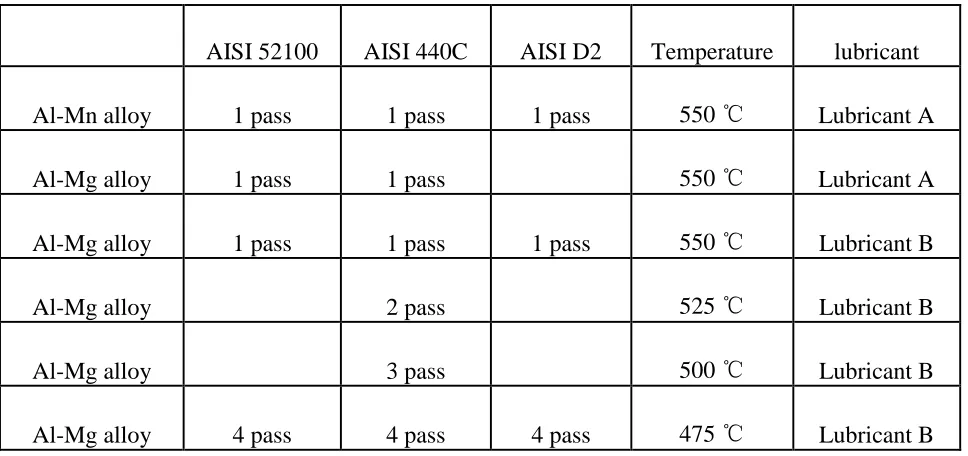
Table 4. Variable process parameters of all experiments done in this study (the empty block is
tests that were not done, and the temperature is the last pass temperature) ... 45
XVI
NOMENCLATURE
COF Coefficient of Friction
EDS Energy Dispersive X-Ray Spectroscopy
EPT Extensive Patch Transfer
FFC Filiform Corrosion
FIB Focused Ion Beam
FWT Full Width Transfer
GDOES Glow Discharge Optical Emission Spectroscopy
PFZ Precipitate Free Zones
RS Relative Softening
SEM Scanning Electron Microscope
SPT Small Patch Transfer
TEM Transmission Electron Microscope
TLT Thin Layer Transfer
1
CHAPTER 1
INTRODUCTION1.1 Background
1.1.1 Aluminum alloys
Aluminum alloys have a very wide application in engineering structures and components
where a light weight or corrosion resistance is required. For example, aluminum alloys
containing magnesium have a high strength to weight ratio and are much less flammable than
other alloys that contain the same percentage of magnesium; that makes these alloys lighter than
other aluminum alloys and make them favored in aerospace applications [1-3]. The typical
aluminum alloying elements are copper, magnesium, manganese, silicon and zinc. The
aluminum alloys can be divided by heat-treatable and non-heat-treatable. Almost 85% of
aluminum is used for wrought products, such as foils, rolled plate and extrusions [3-5].
1.1.2 Heat-treatable and non-heat-treatable alloys
Alloys that respond to thermal treatment are based on phase solubility such as solution
heat treatment, quenching and age hardening. Whether they are cast or wrought, they are referred
to as heat treatable. Many wrought aluminum alloys created mainly through work hardening by
mechanical reduction, as well as some casting alloys, are not as heat treatable; they usually
appear to be non-brittle metals with a reasonably high melting point. Alloys not amenable to heat
treatment are referred to as non-heat-treatable [3,4].
Heat treatable aluminum alloys represent alloys that can be hardened by a controlled
cycle of heating and cooling; as the strength increases by heat treating, the formability may
sometimes be affected. Usually aluminum alloys in the 2000, 6000 and 7000 series are heat
treatable. Non-heat-treatable aluminum alloys are hardened by strain hardening without heat
2
work hardening [1,3,4,6]. The 3000 series is widely used in cooking utensils and chemical
equipment, due to its superiority in handling many foods and chemicals; the AA3104 or 3004 in
particular is the largest volume alloy combination in the industry, with applications in the bodies
of beverage cans. The 5000 alloys have wide applications in the top of the beverage can,
automotive, building and construction areas [4,5].
The aluminum alloy compositions are registered with the Aluminum Association (AA).
The 3000 and 5000 series are alloyed with manganese and magnesium respectively. Both of
these additions increase strength primarily by solid solution hardening and by forming
precipitates such as Al
6 (Mn,Fe), α–Al15(Fe,Mn)3Si2 and Al3Mg2 which could control
recrystallized grain size by pinning grain and subgrain boundaries. At the Eutectic temperature,
the limit of manganese solubility is 1.5 wt% and magnesium solubility is 17.4 wt% in aluminum
(Figure 1) [7-10]. The present system utilized to identify wrought aluminum alloys is the four
digit designation system, shown below:
The 1000 series are essentially pure aluminum with a minimum 99% aluminum content by
weight and can be work hardened.
The 2000 series are alloyed with copper and can be precipitation hardened to strengths
comparable to steel. Formerly referred to as duralumin, they were once the most common
aerospace alloys, but were susceptible to stress corrosion cracking. They are increasingly
replaced by 7000 series in new designs.
The 3000 series are alloyed with manganese, and can be work hardened.
The 4000 series are alloyed with silicon. They are also known as silumin and are heat
treatable.
3
The 6000 series are alloyed with magnesium and silicon, are easy to machine, and can be
precipitation hardened, but not to the high strengths that 2000 and 7000 can reach.
The 7000 series are alloyed with zinc, and can be precipitation hardened to the highest
strengths of any aluminum alloy.
The 8000 series is a category mainly used for lithium alloys, heat treatable.
The 9000 series is reserved for future use [1,2,4]
The work hardening rates can be different for different alloy series, for instance, AA3104,
AA5182 and AA9111 have high work hardening rates at low temperatures and the work
hardening amount decreases while temperature increases, due to the dynamic recovery [11]. The
compositions and grain sizes between different series are different, as shown in Figure 1; even in
4
Figure 1. Optical micrographs of the two alloys a) AA3104, b) AA5182, c) Phase diagram of binary Al–Mg system, d) Phase diagram of binary Al–Mn system [11,14]
1.1.3 Rolling process
For most non-heat-treatable aluminum alloys, the process usually first involves hot
rolling, which leads to significant thickness reduction and preparation for the later forming
process. Rolling is a typical metalworking process and the most common method of
work-hardening (cold-rolling) non-heat-treatable alloys. It has wide industrial application. Figure 2 is a
schematic diagram of the process route for the production of can body stock [15]. It can be
divided into two stages according to the temperature of the work metal. If the temperature is
above the recrystallization temperature, the process is referred as hot rolling; if the temperature is
5
integral part of manufacturing of wrought aluminum alloy sheets, and the main purpose of hot
rolling is gauge reduction. Rolling could change the morphological, optical, microstructural and
electrochemical properties of the surface and near-surface regions compared to the bulk, by
exerting a load and a shear stress on the surface of the workpiece. There are many types of
rolling processes, including ring rolling, roll bending, roll forming, profile rolling and controlled
rolling [1].
Figure 2. Typical process route for can body stock [15,16]
Hot rolling occurs only above the recrystallization temperature of the workpiece material,
which is usually in the range of 0.6T
m, where Tm is the melting temperature in Kelvin. When the
temperature is above recrystallization temperature, the grains deform into equiaxed
microstructures during processing and impede the metal from work hardening. The temperature
must be controlled to remain above the recrystallization temperature, so the finishing
temperature is usually defined 50-100 above the recrystallization temperature. Usually, a
multi stand rolling mill is used in industrial manufacturing. However, the alternating cycles of
6
overall microstructure and texture evolution. The recrystallization between two consecutive
tandem passes could be diminished by modern high-speed tandem mills [17]. However, the
surface of the finished product is always covered with an oxide layer, so pickling or a smooth
cleaning of surface process is needed to reveal a smooth surface [1].
Cold rolling occurs below recrystallization, usually at room temperature. It increases the
alloy strength up to 20%, usually by strain hardening and improving the surface finish. There are
different levels for cold rolling, which are full-hard, half-hard, quater-hard and skin-rolled. The
full-hard level reduces the thickness by 50%, while the skin-rolled level only does so by
0.5%-1%. The skin-rolled is always used to attain a smooth surface, a uniform thickness and the
reduction of the yield point phenomenon [1].
1.1.4 Steel roller alloys
Steel are used in a variety of mechanical applications due to their high strength, hardness
and other properties. In the rolling process, steel alloys play an important role in the rolling of
the tool piece. Although AISI 52100, D2 or 440C steel alloys could be used as tool steel for
rolling aluminum, they have been found, respectively, to contain different levels of chromium
content of an order from low to high. AISI 52100 was one of the first alloys developed for
commercial use as a bearing material composed of 1 wt% carbon and 1.5 wt% chromium. AISI
D2 is also a high-carbon chromium alloy steel, alloyed with molybdeum and vanadium, and it is
a cold work tool steel containing 12 wt% chromium and 1.5 wt% carbon. The AISI 440C can
attain the greatest hardness of any stainless steel after the heat treatment, and can be used for
bearing assemblies such as the ball bearings [18-21]. More chromium content is added to steel
alloys to obtain high corrosion resistance. For example, AISI 440C, which contains about 17 wt%
7
chromium content in the matrix is effective, and in the cases of both 440C and D2, with a
combination of high chromium and carbon contents, Precipitates form carbide [22-24]. Carbides
in 440C are reported to be M23C6 and M7C3, and in D2 to be M7C3, where M refers to metallic
elements that can form carbides. Elements such as Cr, Fe, Mo, V, W, Nb, Ti and Zr are all
typical carbide forming elements, but in these two alloys, M would be mostly chromium [23].
M7C3 carbide is larger and possesses a hexagonal or an orthorhombic unit cell, while M23C6 is
smaller and possesses an FCC unit cell [23,25]. These carbides could become sources of stress
concentration and could form prominent voids in the near regions, which would have a negative
effect on the durability of the steel alloy, but a high population density of carbides could improve
the hardness behaviors of the steel [23]. The different amount of chromium content allows these
different roll materials to obtain different hardnesses and surface morphologies that could
significantly affect rolled aluminum surface defects.
1.2 Thesis objective
There has been limited study done in the area of surface defects of hot rolling aluminum
alloys under the effects of different roll materials. This study examines the surface defects that
occur during the hot rolling of Al-Mn and Al-Mg alloys. Both of the alloys are widely used in
the production of beverage cans.
The roller currently used in the industry is the steel alloy roll. Usually, a higher roll
hardness gives more thickness reduction to rolled aluminum and enhances metal working
efficiency during hot rolling. AISI 52100, D2 and 440C steel alloys have been found to contain,
respectively, different levels of chromium content of an order from low to high. The different
concentrations of chromium content and elemental composition means that these different roll
8
attributed to the varieties of surface morphology could significantly affect rolled aluminum
surface defects.
The objective of this research pertains to how processing parameters such as roll
materials, number of passes and lubrication conditions affect the development of surface defects.
1.3 Organization of thesis
This thesis is arranged into six different chapters, each of which is briefly described
below.
Chapter 1 introduces the background information related to this thesis and the research
objectives and organization of the thesis.
Chapter 2 provides a literature survey related to this thesis and includes information on
previous research that has been done so far. It focuses on the disturbed layer and surface defects
occurring in aluminum alloy surfaces during thermo-mechanical processing along with how the
disturbed layer affects the mechanical properties of the aluminum alloy. It also looks at how
some factors affect the formation of the disturbed layer.
Chapter 3 introduces the experimental procedures. It includes descriptions of the
experimental setup and sample preparation as well as the aluminum alloys and steel roll alloy
elemental composition details. It describes the working principles of the hot simulation used in
this research as well as the analytical tools used to examine the surface defects on the specimen
surfaces.
Chapter 4 describes the results obtained by WYKO, SEM, and EDS. This chapter is
divided into two parts. One is the results related to the Al-Mn alloy, and one is the results related
9
Chapter 5 discusses the results obtained. It first discusses the effect of three different roll
materials on the two different aluminum alloy surfaces. It then moves to the effect of number of
the passes along with lubrication effects during hot rolling simulation.
Chapter 6 summarizes the conclusions of this research. It presents a summary of the
10
CHAPTER 2
REVIEW OF LITERATURE2.1 Introduction of disturbed layer
During metal working, the surface and subsurface regions of a metal sheet are always
subjected to different conditions and treatments. Material transfer has been a long term problem
due to the interactions between the metal and the tool surface. The material transfer can take
place through a variety of mechanisms: microcutting, adhesion, delamination, etc. The
transferred metal can be oxidized and retransferred back to the workpiece surface, resulting in
distinct surface disturbance, which adversely influences the properties of the surface. Rolling is
an integral part of a wrought aluminum alloy sheet, and the main purpose of hot rolling is gauge
reduction. Rolling could change the morphological, optical, microstructural and electrochemical
properties of the surface and near-surface regions compared to the bulk by exerting a load and a
shear stress on the surface of the workpiece. Both hot and cold rolling could induce the
formation of a disturbed layer, and the subsequent cold rolling after hot rolling always provides
strain hardening [16,26,26,27]. In earlier research into the disturbed layer, Fishkis and Lin [28]
found that a subsurface was formed in the process of rolling a magnesium-containing aluminum
alloy that had a different microstructure, oxide content and alloy distribution from the bulk
material. The thickness of the subsurface layer was non-uniform and decreased as the rolling
pass increased.
Deformation of the aluminum surface during hot rolling provides high compressive and
surface shear stresses resulting from the friction between the rolls and the metal. The formation
of the disturbed layer is attributed to these stresses coupled with the high temperatures involved
and it is responsible for altering the local composition and microstructure of the surface and
11
a surface region of continuous metal oxide, which has nanocrystalline oxide grains 25-150 nm in
size, and a subsurface region of a "refined" grain structure with 50-200 nm diameter grains,
rolled-in oxide particles and a fine distribution of intermetallic particles. The thickness of the
disturbed layer varies from 200 nm to 8 m [29].
The disturbed layers induced by rolling are relevant for the productivity of the aluminum
alloy sheet since the deformed layer is not always removed by post-production treatment such as
anodizing or caustic etching [30]. This layer also has a strong influence on the adhesion,
corrosion resistance, optical appearance and weldability of the metal. It is important to
investigate this rolling induced disturbed layer [28,29,31-33].
The mechanical properties of the disturbed layer are different from the properties of the
bulk alloy in several respects. Observation of the disturbed layer of rolled aluminum after a
tensile test showed fibres connecting in cracks; this formation of elongated fibres indicates the
ductile behaviour of the disturbed layer during plastic deformation of the aluminum alloy [32].
However, this surface layer also holds the property of a higher strength than that of the bulk alloy,
due to the ultra-fine equiaxed grains of the microstructure [34].
There are various techniques by which to study the disturbed layer, such as
cross-sectional transmission electron microscopy (TEM), which can indicate the presence of disturbed
layers characterized by a refined grain structure with rolled-in oxide particles and a fine
distribution of intermetallics. Scanning electron microscopy can be used in identifying shingles
and transverse cracks on the surface of the alloy which have been identified as an indication of
the disturbed layer [27-29]. Various depth profiling techniques can be applied as well, like
qualitative glow discharge optical emission spectroscopy (GD-OES), which has been used to
12
determine whether the segregated alloying element is present in a solid solution or as second
phase particles. Checking the total reflectance (TR) can also examine for the existence of rolled
in oxides [16,35].
2.2 Microstructure of the disturbed layer
The structure of the disturbed layer depends on the alloy composition and also the
process conditions. Typically, a multilayer structure is always obtained by the rolling process.
The outermost deformed layer is characterized by ultrafine, equiaxed grains. Then, a transition
region is sandwiched between the outermost deformed layer and the bulk microstructure, which
is characterized by microbands consisting of elongated grains aligned parallel to the working
surface due to the shear stress generated during rolling. The precise mechanism of the formation
of the microbands observed by Zhou et al. [27] remains unclear, but the most widely suggested
theory is that dynamic recovery effects and dislocation loss may be responsible for their
formation. The change of dislocation density strongly affects materials' mechanical properties
and influences microstructures such as the orientation of grains [36-39].
Fishkis and Lin [28] observed that the grain size of the disturbed layer materials was
more than 25 times smaller than the grain size of the bulk, which contributes to Zener pinning.
The deformed surface layer has extremely fine grains compared to the bulk, and these ultra-fine
grains are pinned by rolled-in oxides and intermetallics or dispersoids. These second phase
particles may be caused by the secondary precipitation during heating [40], preventing grain
growth of the surface layer during subsequent heat treatment, which referred to as Zener pinning
[16]. These fine second phase particles present within the subsurface layer acting as Zener
barriers by locking the grain boundaries and thereby preventing further recrystallization
13
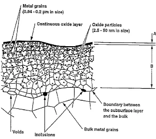
Figure 3 shows the microstructure of the subsurface region schematically. The subsurface
layer contains the microcrystalline oxides mixed with small grained metal and covered by a
continuous oxide layer. The thickness of the continuous oxide layer decreases as the rolling
processes [28].
Figure 3. Schematic representation of subsurface layer containing microcrystalline oxides mixed with small
grained material and covered with a continuous surface oxide. Layer A represents the surface oxide layer and
layer B represents the subsurface ultrafine grained layer [28]
The intermetallics appearing on the surface of the material surface region after rolling are
fine and irregularly shaped, as Figure 4b shows. This is due to the breaking up and smearing out
14
The size and distribution of intermetallics, rolled-in oxide particles or dispersoids have a
strong effect on the recovery, recrystallization and grain growth, which results in an uncertain
grain size in the disturbed layer [40].
The second-phase particles are usually sufficiently small [26,42], and if the oxide particle
diameter exceeds a critical diameter, the boundary migration can occur so that grain growth
restarts:
[28]
Where is the mean grain radius, f is the volume fraction of the second-phase (oxides)
particles, and Z is the ratio of the radius of a growing grain to that of its neighbors. Anderson et
al. [1] found the fraction of second-phase particles between pinned grains is significantly greater
than between random intersections. Therefore, the limited grain diameter after being pinned by
second-phase particles can be calculated by Anderson et al.’s equation:
[28]
The volume fraction of oxide incorporated into the near-surface deformed layer is associated
with process parameters such as abrasive medium, temperature, roll grinding, inter-annealing
treatment, lubrication regime and lubricant formulation [27].
Figure 4. SEM backscattered micrograph of the surface of Aluminum alloy AA5050: (a) as-cast; (b) hot roll
15
The subsequent cold rolling can distribute the fine micrograined layer over a larger
surface area and reduces the thickness of the deformed layer. Nevertheless, cold rolling alone
without the previous hot rolling process, cannot incorporate second-phase particles that are
necessary to pin the refined grain growth in the deformed subsurface layer [26,27,35]. Moreover,
the oxides formed after hot rolling are crystalline, but after cold rolling, the subsurface oxide
particles are amorphous, as the temperature at the cold rolling stage is indeed too low to initiate
oxide crystallization [43]. Figure 5 systematically shows the condition of the different
microstructures of the disturbed layer (near surface) formed when hot rolling is involved and
when it is not involved. Type A is the microstructure disturbed layer with hot rolling is involved,
and type B is under cold rolling only; at lower temperatures, there are no precipitates or oxides in
the grain boundaries.
Figure 5. Schematic diagrams showing the microstructure of near-surface deformed layer introduced by
rolling: (a) type A is hot rolling involved and (b) type B under cold rolling without hot rolling involved [27]
2.3 Content distribution in disturbed layer of aluminum alloy under rolling
The disturbed layer formed during rolling contains both oxide particles and a different
intermetallic particle distribution compared to the bulk material. Therefore, the mixed phases of
16
aluminum oxide particles [26,28], but almost all the intermetallics are rich in Al, Mg, Fe, Mn and
Si (depending on aluminum alloy content distribution); these includes AlMn6, AlSi, Mg2Si and
AlMnSi [34]. The increased number of fine intermetallic particles is due to the fragmentation of
existing particles, nucleation and the growth of new precipitates [16,35,44]. The composition of
the precipitates remains almost constant during the subsequent rolling [41]. The difference of
particle distribution between the bulk and the disturbed layer is due to the plastic strain induced
by continuous enhanced shear deformation in the surface and near the surface region. During
rolling, the intermetallic phases are smeared over and covered with the softer aluminum matrix,
and then break up into smaller fragments. By exposure to the high temperature process, the large
plastic strain results in the increase of secondary precipitation of fine dispersoid particles; this
contributes to different particle distribution between the bulk and the disturbed layer [26].
Al, C, O, Si, Fe, Mg, Cu and Pb are discovered in the surface and near surface layer after
rolling, according to Buytaert’s study, which use the aluminum alloy of AA1050 that contains
0.075% Si, 0.34% Fe, 0.005% Mn, 0.008% Ti, 0.003% Cu, 0.003% Zn, 0.002% Cr, 0.001% Mg,
0.001% Pb and 99.5% Al [39]. The presence of carbon could be the result of rolling lubricants
[29]. Figure 6 shows that there is always an increasing tendency of Al with depth, and oxygen
displays a strong decreasing evolution away from the surface, which could confirm the presence
17
Figure 6. Quantitative r.f. GDOES depth profile of hot rolled AA1050 [39]
Both the rolling and the heating process for aluminum alloy induces significant Mg
enrichment at the surface and in the near regions. Al2CuMg is a typical precipitate formed at low
temperature, but usually Mn dispersoids exist at a higher temperature [45]. The diffusion of Mg
to the surface during heating and hot rolling is responsible for magnesium oxide formation,
which contributes to the formation of the disturbed layers, since Mg reacts with the oxygen and
aluminum to produce MgO and MgAl2O4; this provides the Zener pinning that establishes the
fine-grain surface structures. Also, the fine-grained material always has a larger interdiffusion
coefficient than coarse-grained material which leads the Mg diffusion to the aluminum surface as
well [33,46]. The raised magnesium content has an inverse ratio with the depth below the surface
(Figure 7), and this depth is related to the thickness of the subsurface particle layer in each case
[15,16,35,42]. Although other metal oxide particles also exist in the subsurface region, Mg
always has the second-most particles in the aluminum alloy; thus, the subsurface structure and
18
Figure 7. a) Metallic element distribution as a wt% amount of the total metal content in the subsurface layer
of the laboratory rolled sample of aluminium alloy AA3104 [1]. b) Distribution of Mg in the surface layer of
aluminium alloy AA3104 measured for only reheated and reheated followed by laboratory rolled specimens
[42]
For aluminum alloys that contain magnesium, the continuous oxide layer that covers the
subsurface layer is comprised predominantly of MgO. The composition of the oxide-metal mixed
layer is not homogeneous, and it is found to be a mixture of MgO, γ-Al
2O3, MgAl2O4 and
amorphous aluminum oxide [15,28,42]. However, only the MgO content increases as the rolling
process continues, due to lower temperatures during the later passes and due to the increasing
magnesium content in the oxide layer (Figure 8) [12,27,28]. The MgO dominated oxide layer
contains a considerable amount of porosity and cracks in order to allow oxygen to react with
magnesium and other metals, to grow the oxide layer [12]. The magnesium content also results
19
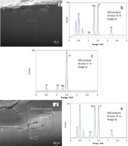
Figure 8. a) FIB image of AA3104 surface hot rolled in 1 pass at 753 K and with forward speed 12%; b) EDS
analysis from the area marked as "d" in image a; the elements Pt and Ga are from the protective coating and
the ion source respectively; and c) EDS analysis from the area marked as "e" (bulk material) in image a; d)
evolution of AA3104 surface hot rolled in 2 passes in the same direction, temperature and forward speed; e)
20
However, aluminum alloy surfaces could oxidize either with or without heating. The
fresh surface of Al-Mg alloys always tends to generate a thin, amorphous layer of aluminum
oxide during the initial stages of oxidation, without tribo-layers. If the heating is continually
applied, the magnesium atoms diffuse to the surface, as shown in Figure 9, and promote the
formation of MgO on the surface and MgAl
2O4 at the interface between the oxide layer and the
bulk material. The thickness of the magnesium rich oxide layer and the magnesium oxide
contents increase with the rising magnesium content in the alloy [32]. The oxidation rate
decreases during the reheating process, but the rates of magnesium diffusion to the alloy surface
increase with temperature, unlike steel, in which the oxide layer becomes thinner with a higher
oxidation temperature [27,42,47].
Figure 9. (a) GDOES depth profile analysis from the surface of an as-polished sample; (b) GDOES depth
profile analysis from the surface of a sample polished and heated to 753 K for 840s [29]
The Mg content reduces along with the reduction in disturbed layer thickness through
21
reason is that the Mg content is diluted by the inevitable introduction of fresh metal by the
increasing of the surface area caused by the deformation process, and the second is that some
surface materials are transferred on to the rolling tools and form a surface coating, as shown in
Figure 10 [15,29,42].
Moreover, subsequent cold rolling can break up and smear out rolled-in oxide islands in
the near-surface of rolled aluminum [35,39]. In aluminum alloys containing magnesium, Plassart
et al. [43] observed aluminum nanocrystals in the intermetallic particles, found to be caused by a
reduction of Al2O3 reacting with metallic Mg that occurred during cold rolling, according to the
following:
Al2O3 + 3Mg 3MgO + 2Al [43].
which, on the other hand, proved the Mg diffusion and subsequent oxidation.
Figure 10. Image showing material transferred from the stock surface to the work roll surface after the
22
The lubricant in aluminum hot rolling is usually in the form of an oil-water emulsion.
There is lubricant entrapment on the surface and in the near surface region as well. It may be
caused by the reaction of the lubricant with the surface oxide film during rolling, by the
entrapment of lubricant in surface defects such as holes, cracks, etc., or by closure due to the
smearing out of the surface during subsequent rolling. The different surface structure of rolled
metal and the surface geometry of the rolls could also attenuate or accentuate lubricant capture
on the rolled surface area [29,41,48] .
2.4 Mechanisms of disturbed layer formation
Since the majority of the subsurface deformation takes place at earlier stages of hot
rolling, the mechanisms of these earlier stages of hot rolling are always investigated most
thoroughly and considered most significant [26]. The surface damage is very severe during
earlier rolling passes, and then the damage is distributed to a larger surface area due to further
rolling passes, which makes it less severe after later passes. The percentage gauge reduction is
always highest at the first roll pass and decreases as subsequent passes proceed, and the
deformation is most severe in the roll-bite part of the workpiece surface, as shown in Figure 11.
The thickness of the surface layer decreases, and properties became more distinct compared to
23
Figure 11. Schematic representation of the roll-bite. Cross-sectional TEM analysis was carried out along the
planes A (just before entry), B (just after entry), C (neutral plane) and D (just after exit) [41]
First, it is known that the subsurface layer is always covered with a continuous oxide
layer. The thickness of the continuous oxide layer decreases as the rolling proceeds. This is
explained by the breaking up of the original thick oxides formed during earlier rolling passes and
their distribution to a larger surface due to further rolling, as well as by the descending oxidation
rate due to the lower temperature at later passes [27,28].
Since the rough roll has a grooved structure on the surface, the hot aluminum squeezes
into the grooves and forms micro wedges (shingles) during the initial stages of surface damage
from rolling as shown in Figure 12a. These wedges deform more easily than the flat surfaces,
due to lower constraints, and when the micro wedges slide against the groove on the roll surface
they experience more severe plastic deformation. This is even more severe if the groove depth is
24
Figure 12. AA3104 surface hot rolled in 1 pass at 753K and with 12% forward speed; (a) localized shear
deformations in the form of shingles; the inserted image magnifies the area in the bracket; (b) low
magnification image of the trench after FIB milling; the surface was platinum coated first in order to avoid
damage due to exposure to ion beam; (c) cracks formed beneath and parallel to the surface [29]
Fishkis and Lin [28] concluded that there was a three-step process to the mechanism of
subsurface layer formation during rolling. First, transverse surface cracking and adhesive and
delamination wear occurs on the surface and near surface region. After that, surface defects are
filled with wear debris, consisting of fine intermetallic, dispersoid and oxide particles.
Eventually, thin metal layers cover all surface defects during the continuous rolling process
25
The holes then develop into sub-surface cracks in subsequent rolling passes. The
transverse surface cracking is the initial stage, and also the most important stage, of the
formation of the disturbed layer. It is caused by the lower ductility that contributes to the surface
cooling, by the brittleness of the surface oxide layer of the surface layer and by shear stress
obtained during rolling [27,28,41]. As the rolling passes increase, some of the localized shear
deformed areas can delaminate, as Figure 12c shows; they transfer onto the roll surface and back
to the sheet surface during the subsequent rolling process. This delaminated debris oxidizes and
contaminates the lubricant and then embeds in the rolled surface, becoming part of the disturbed
layer as rolling continues. The re-deposited layer also contributes to the increasing thickness and
structural changes of the disturbed layer[29].
There are always fine grained structures and incorporated oxide particles in the surface
and near surface layers after the rolling process. They are caused by large shear deformation
combined with repeated fracturing and re-welding of the surface material due to friction between
the aluminum sheet and the work-roll surface during heat treatment. The shear strains generated
in the surface and near-surface regions are severe, with a gradient distribution that gradually
decreases from a maximum at the surface to zero in the bulk alloy. This is sufficient to cause the
geometric dynamic recrystallization of the grain, resulting in significant microstructure
refinement and the formation of the deformed layer. It initiates near the surface before extending
gradually towards the centre [49]. Therefore, the microstructure variation at various depths from
the surface is continuously a reflection of the strain distribution [50-52]. Alloying elements or
impurities in the alloy in the form of intermetallics can act as grain refiners, then oxide and
lubricants introduced to the surface could pin the subgrain structure and also act as grain refiners
26
grain refined surface layer, because they do not have sufficient impurities to act as grain refiners
[53].
2.5 Optical appearance
Usually, the aluminum alloy surface will keep an apparent shine with a high level of
optical reflectance in a dry environment due to the formation of the protective oxide layer of
aluminum. The optical reflectance of the surface layer after the rolling process has been found to
be much less than that of the bulk alloy predominantly due to the presence of rolled-in oxides
[16]. The oxide particles mixed in the subsurface highly decrease the total reflectance (TR) upon
the rolling of aluminum (Figure 13), so that the oxide-rich subsurface is the main reason for the
reduction of TR in rolled aluminum alloys. The TR can be increased by removing more material
in order to gradually remove the incorporated oxide particles. Therefore, lower TR values
indicate the presence of a higher number of incorporated oxide particles in the respective sample,
so the method of TR for the optical reflectance can be used to evaluate the presence of
subsurface oxide-rich layers upon the cleaning and etching treatments of rolled aluminum alloys.
Since the TR value is inversely proportional to the number of incorporated oxide particles, it
could also be used to calculate the thickness of the surface layer, which appears to be a
cost-effective, quick and reliable technique for the estimation of the thickness of the subsurface layer
[41].
Surface treatment on the alloy, such as alkaline etching or chemical cleaning with
Nabuclean and CrO3 or H3PO4, could be an effective way to affect the surface appearance of
rolled aluminum alloy. Buytaert et al. [54] found that the alkaline etching preferentially attacks
27
H3PO4 dissolves the oxide-rich regions leaving the aluminium matrix un-attacked, and form a
layer containing Cr on surface.
Figure 13. Schematic of the influence of rolled-in oxides on the Total Reflectance (TR) [41,50]
2.6 Effect of disturbed layer to filiform corrosion (FFC)
Filiform corrosion (FFC) on aluminum alloys can be severe in marine, tropical or coastal
areas, because it also depends on humidity and the formation of hygroscopic corrosion products
in the head of the filament. The filiform corrosion can even propagate at a relative humidity as
low as 30%, since the dissolution point of aluminum chloride is approximately at 30-35%
relative humidity at 25 , and it will form an aqueous solution above with a solid salt below.
Therefore, increasing the humidity and decreasing the pH value may increase the propagation
rate of the filiform corrosion. However, it may propagate again even after a dry period, unless a
complete hydrolysis of the corrosion products in the head of the filaments leads to a
repassivation. In that case, the FFC process is dominant during dry conditions and starts to
propagate when the environment becomes humid again, meaning that it could restart without an
28
The anodic activity is the leading factor for the propagation behavior of FFC on
aluminum, as Figure 14 shows. The aluminum is dissolved in the head of a filament and oxygen
is reduced, while the corrosion products are deposited in the tail and the oxygen is mainly passed
through the tail, since it is much easier for oxygen to go through the porous corrosion products
than the coating. Therefore, the initiation of filiform filaments is reduced for the thicker porous
layer [56].
Figure 14. Schematic view of a filiform filament on aluminum [56]
The susceptibility to corrosion and surface reactivity are not particularly related to grain
size but to differences in the intermetallic particle distribution and the solid solution content. The
matrix and particles such as precipitates, dispersoids and intermetallic particles in an alloy can
have a significant influence on its corrosion behavior [56,57].
Intermetallic particles can increase the probability of the initiation of FFC, whereas the
1000 series aluminum alloys (containing mainly pure aluminum) have better FFC resistance. The
intermetallic particles can act either as cathodes or anodes in order to affect the rate of
electrochemical processes by promoting the dissolution of aluminum. Thus, they may play an
important role in the location of filiform corrosion initiation[26,55,56]. As Figure 15 shows, the
29
reduction reaction. The intermetallics are surrounded by dissolved aluminum until the cathode is
detached or a new one is reached. As the cycle continues, the anodic section could turn to
cathodic in order to take the reaction for oxygen reduction. As more intermetallic particles
become available and the cathodic and anodic surface areas increase, then the corrosion current
density increases [56,58,59].
Figure 15 Effects of intermetallic particles on the propagation behavior of filiform filaments [56]
The altering of the surface layer makes it more prone than the bulk material to corrosion
attacks. Therefore, thin surface layer corrosion always leads to a rapid and extensive propagation
of underfilm corrosion [16]. The hot-rolled material has more susceptibility to filiform attack
than cold-rolled material, and this susceptibility further increases with heat-treatment [44]. The
filiform corrosion usually starts at discontinuities, breaks, etc in the surface area. It needs
sufficient relative humidity, oxygen, temperature and surface defects as well as the right material
to be induced. Under filiform corrosion, aluminum exhibits small hydrogen bubbles at filament
30
[60].
The corrosion first propagates along preferred grain boundaries and then develops into
the bulk grains. Figure 16 below shows the two stages of filiform corrosion after hot rolled
aluminum alloy, which are surface-active filiform corrosion and successive-pitting filiform
corrosion. At the surface-active stage, the localized corrosion attack is intergranular and very
superficial, having less than 2 µm depth; it propagates at or adjacent to grain boundaries along
the near-surface layer, accelerated by the rapid dissolution of magnesium oxide and the presence
of manganese/iron-rich dispersoids, with no penetration into the bulk metal. After the
near-surface deformed layer is corroded, the stage of successive-pitting corrosion occurs. The depth of
penetration may even reach to 10 µm, and the corrosion attack is preferred at grain boundaries as
well. The intergranular corrosion could result from the density change of dislocations during
shear deformation in rolling, since the grain stored energy is determined by the density of the
dislocations. Therefore, the microstructural differences between grains, such as size and
31
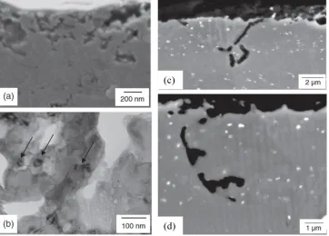
Figure 16. Surface-active filiform corrosion (left side figure): (a) SEM of cross-section show the initial stages
of filiform corrosion with attack of grain boundaries in the deformed layer; (b) TEM showing the dispersoids
(indicated by the arrows) in the corrosion product. SEM of successive-pitting filiform corrosion (right side
figure): (c) corrosion initiated at a grain boundary of the aluminum matrix after the near-surface deformed
layer has been consumed; (d) corrosion growth into one of the grains [33]
Afseth et al. [26] found that high temperature heat treatment for the aluminum alloy
AA3005 results in a drastic loss of FFC resistance, and that is attributed to the higher plastic
deformation undergone by the near surface layer, caused by the secondary precipitation of
manganese bearing intermetallic particles in this region. Therefore, the FFC properties of rolled
aluminum are strongly influenced by the intermetallic particles and the solid solution levels of
impure elements in the near surface region; for instance, a higher density of fine intermetallic
particles and lower manganese solid solution content than that of the underlying bulk metal
32
The higher corrosion rate contributes to the higher cathodic or anodic activity on the
surface during the rolling process due to an increased number of Fe- and Mn-rich precipitates for
some Mn containing aluminum alloys [16,44]. Alloys with a high level of manganese, such as
AA3005, always have a higher susceptibility to filiform corrosion [30,57]. α-AlMnSi could be
the point at which the corrosion process is induced. It is believed that this type of corrosion is
promoted by the electrical potential between the α-AlMnSi and the matrix. These preferential
precipitation dispersoids can be prevented by controlling the level of manganese in solid solution
or by reducing the manganese in the alloy [57]. However, the depletion of Mn from solid
solution into the second phase particles in the deformed surface layer also enhances FFC
susceptibility, but since the Mn content does not change continuously during the rolling, the
depletion of Mn is not the main factor that is responsible for enhanced FFC susceptibility [16].
Therefore, a simple method of rendering aluminum sheet surfaces resistant to FFC is to remove
the active layer by caustic etching or by using other appropriate treatments [15,53,61].
Coating is an efficient way to prevent filiform corrosion; the degree of adhesion related to
the surface roughness of the coating could be a principle influence on the filiform corrosion rate.
The coating usually breaks down above the filiform corrosion heads and tails, and the same
phenomenon may occur in the disturbed layer [62]. Chromatizing the aluminum alloy could
improve the resistance to FFC as well, due to the formation of a stable oxide layer by the
remaining hexavalent chromium ions serving as active corrosion inhibitors [56].
2.7 Rolling parameters that affect the surface layer
The rolling parameters such as temperature, rolling geometry, roll surface morphology,
state of lubrication, forward speed, number of rolling passes, roughness of the rolls and the roll
33
[29,32]. For instance, increasing rolling passes can increase the generation of localized shear
deformed areas, which makes the alloy more prone to form the disturbed layer. Also rolling in
different directions elongates the surface, embedding the shear deformed areas more deeply into
the surface than if rolled in same direction. Furthermore, the thickness of the disturbed layer is
extremely commercially important in order to minimize the cost of post-production treatment
such as anodizing, caustic etching, etc. [41]. The hot rolling process is more significant for the
formation of the micrograined surface layers than is subsequent cold rolling. The thickness of the
disturbed layer is greater at higher forward rolling speeds [29]. Process parameters such as the
type of rolling schedule and equipment that represents forward, reverse or and multistand milling
can also significantly affect the microstructure [49].
2.7.1 Heat treatment and strain effect
The recrystallization of grains has two critical prerequisites; one is to have a critical
deformation, and the other is to reach a critical temperature. Therefore, the heat treatment of a
rolled aluminum piece has significant effects on the microstructure of both the bulk alloy and the
disturbed layer. The greater the deformation produced, the higher the nucleation sites and the
nucleation rate of the recrystallizing grains will be. The rates of magnesium oxidation and
diffusion to the alloy surface increase with temperature, so that the thickness of the oxide layer
and quantity of rolled in oxide particles decreases in the later passes since the temperature goes
down [27]. However, the grain size becomes stabilized, since the second-phase particles present
in the disturbed layer act as grain refiners; the grain size does not change with further annealing
[34].
As in the literature mentioned above, the size and distribution of the dispersoids in an
34
treatment, and the heating rate strongly affects the size and distribution of the dispersoids. For
instance, the Mn-containing dispersoid Mg2Si is preferentially formed on the area on which Mg
and Si lie on while heating at a fast rate, but it nucleates in a uniform distribution in the matrix at
a slow heating rate (as shown in Figure 17) [40].At initial stages of precipitation by annealing,
there are multiple kinds of intermetallics or dispersoids, but as the temperature rises, only the Mn
precipitation process occurs [45].
Figure 17. Optical micrographs of the 6082 alloy after homogenization: (a) rapidly-heated specimen; (b)
slowly-heated specimen. PFZ stands for precipitate free zones [40]
Annealing promotes the preferential precipitation of intermetallic particles in the disturbed layer,
which increases the density of cathodic sites in the surface layers to induce corrosion. This
preferential precipitation can be prevented by controlling the level of manganese in solid solution
or by reducing the manganese in the alloy [57]. However, annealing has little or no effect on the
thickness of the subsurface layer and does not significantly affect the examined elemental
distribution; apparently, only the magnesium, carbon and oxygen are affected, but intermediate
![Figure 1. Optical micrographs of the two alloys a) AA3104, b) AA5182, c) Phase diagram of binary Al–Mg system, d) Phase diagram of binary Al–Mn system [11,14]](https://thumb-us.123doks.com/thumbv2/123dok_us/1416201.1174170/21.612.99.523.72.408/figure-optical-micrographs-diagram-binary-phase-diagram-binary.webp)
![Figure 6. Quantitative r.f. GDOES depth profile of hot rolled AA1050 [39]](https://thumb-us.123doks.com/thumbv2/123dok_us/1416201.1174170/34.612.129.492.75.298/figure-quantitative-gdoes-depth-profile-hot-rolled-aa.webp)