ISSN(Online): 2320-9801
ISSN (Print): 2320-9798
I
nternational
J
ournal of
I
nnovative
R
esearch in
C
omputer
and
C
ommunication
E
ngineering
(An ISO 3297: 2007 Certified Organization)
Vol. 4, Issue 4, April 2016
Automatic Headlight Beam Shifter
for
Controlling High Beam to Low Beam of Vehicles
Prof. Balaji Wattamwar1, Raghavendra Rao2, Pratik Vyas3, Mithilesh Tipkari4
Associate Professor, Department of E & TC, Maharashtra Institute of Technology, Aurangabad (MS), India1.
UG Students, Department of E & TC, Maharashtra Institute of Technology, Aurangabad (MS), India234.
ABSTRACT: Today, one of the biggest problems Vehicle drivers in India are facing during night is the temporary loss of vision due to the Upper beam (high beam) coming from the Vehicle in the opposite direction. Moreover, the victims of this problem are mostly the students who are the backbone of their families. We have decided to undertake this project especially because this problem has become more dominant in recent years. Over five lakh accidents take place in the country annually, out of which, 41% (Approx. 2 Lakh) are due to road mishaps during night, and 18% (Approx. 90,000) are due to the vehicle headlight glare. In the current scenario, most of the automobile manufacturers in India have zeroed in on the Mass Production of their cars in order to fulfill their economic and financial goals without considering the accidental factors arising from the situation mentioned above. Automobile manufacturers like BMW, Skoda, Audi, Mercedes (and more) have provided facilities like intelligent headlight technology in their car models, which act as a remedy to this problem by reducing accidents by 60-70%. But these are only limited to their high end models ( > 20 lakh and so on) due to which there arises a question for the middle class buyers about road safety. This project is targeted to facilitate such buyers so that they also can follow the protocol of Road Safety. Currently there is no provision for switching the headlight beam of the vehicle, automatically in mid-range vehicles. The Central Motor Vehicles Rules 1989 and Central Motor Vehicles Act, 1988, have chalked out certain Protocols related to the situation mentioned above. Operated by the Synergy of a Microcontroller and a Sensor, this device is capable of automatically shifting the Upper beam of the vehicle coming from the opposite direction, to the dipper beam, thus eradicating the problem of vision loss and avoiding accidents due to it. In the following sections we define the principle and design of the "Automatic Headlight Beam Shifter" device.
KEYWORDS: Temporary Loss of Vision, Headlight, Troxler effects, glare luminance, Light sensor, RF Communication, Protocol of Road Safety.
I. INTRODUCTION
The number of vehicles on our roads is burgeoning day by day. This, in turn forced almost all the vehicle manufactures to think about the extra safety instruments and electronic controls to provide with their products for giving the users a safety, derived in all road conditions through a mass flow traffic. If asked, one will always mention that the right driving is very cumbersome due to the dazzling light problems and the frequent dipping of headlights by manual means that often causes fatigue to the driver particularly at the time of peak traffic. There are only a few Indian cities like Dispur (capital of Assam) where the State Government has made it mandatory for the drivers to use low beam at night. But apart from this, the Protocol is being ignored by almost every driver and the situation has become intolerable now. In order to solve this problem, there arises a necessity of switching the upper beam to dipper beam of the vehicles during night automatically.
ISSN(Online): 2320-9801
ISSN (Print): 2320-9798
I
nternational
J
ournal of
I
nnovative
R
esearch in
C
omputer
and
C
ommunication
E
ngineering
(An ISO 3297: 2007 Certified Organization)
Vol. 4, Issue 4, April 2016
lowered, and where accordingly. As this unit is well connected to the lighting system of the vehicle, we have to look short into the type and construction of a head light before discussing the wiring diagram or the construction of Automatic Headlight beam shifter.
II. RELATED WORK
2.1 Headlamps
The modern lighting system consists of switches, lamps, wiring harness, and fuses or circuit breakers. It may be mentioned that the primary purpose of the headlight design is to produce illumination over considerable distance ahead of the vehicle and enable the driver to drive at reasonable speeds at night with safety. But the provision should also be made that the drivers of other vehicles coming from the opposite direction not to experience a glare. For this purpose a dipped or meeting beam is also provided for maintaining the reasonable speed with safety without dazzling the coming driver. To prevent dazzle to the oncoming driver during particularly misty or hazy conditions the light about the horizontal should be cut off. This is called dipping of the head light beam. In an average car, the lighting system consumes about 70 - 75% of electrical energy when driven at night. In terms of amperage the consumption may be from 24 - 40 A at night for al purposes including the radio, heater, and transmission controls.
Light Source: There are two kinds of light sources, namely, the one that emits light and the other that reflects light. The filament of the electric lamp is the primary source, while the reflector is referred to as the secondary source. The intensity, color and distribution are the important characteristics of any light source. The headlight is composed of three elements:
1. The light filament that gives off light when a current flows through it. 2. The parabolic reflector that reflect the light in front: and
3. The lens that refracts of distorts the light beam into an illuminating Pattern.
The present day headlights are the outcome of a lot of research and development. Earlier a single electric bulb of the carbon filament type was employed. The bulb was placed at the focus of a parabolic silvered reflector in order to give a parallel beam of light. The following figure shows a parabolic reflector with bulb, the lines showing light rays emitted from the filament of the bulb in all directions. This type of headlight given a parallel light beam, that saves greater illumination nearer the axis. It may be mentioned that the bulb itself and the intensity of light fall off towards the outer portion of the beam block a small amount of light. From figure it may be seen that if the bulb filament is moved from position 'd', the focus of reflector, to a position 'a', the light beam 'abc' will no longer be a parallel one but will become divergent. On the contrary, if the filament is moved to position 'f' the beam will take the course a shown by 'fog' and will meet at a point on the axis of the bulb. It may be mentioned that by a single adjustment of the bulb, the beam cane be concentrated at a ore- determined distance ahead of the vehicle in order to give a spot light effect. On the contrary, if the filament is moved to position 'f' the beam will take the course a shown by 'fog' and will meet at a point on the axis of the bulb.
Formerly the headlight was provided with certain means of adjusting the bulb holder with respect to the reflector along with the bulb axis in order to focus it. It had to be done up every time the bulb was changed. This was essential, otherwise it would cause increased dazzle to other motorists. The filament is encased in an airtight bulb in order to prevent burning up of the white-hot filament because of oxygen in the air. The reflector is generally of polished metal and it throws all the light rays into a cylindrical beam.The lens is made up of a number of glass prisms molded together and they bend the beam of light into an oval pattern which is aimed ahead of the vehicle and somewhat in the downward direction. A part of the light is spread out in front of the vehicle for providing local illumination, whereas the rest of it is focused into a hot spot that provides distant illumination. The first major advancement in headlight Design took place with the introduction of pre- focused bulbs. It has two filaments, one for normal driving and the other for city driving or for overtaking. These days even two sets of headlights are used for the above said purposes. Generally a foot selector switch is provided, which enables the driver to select either the normal driving or the passing beam.A part of the light is spread out in front of the vehicle for providing local illumination, whereas the rest of it is focused into a hot spot that provides distant illumination.
2.2 TROXLER’S EFFECT
ISSN(Online): 2320-9801
ISSN (Print): 2320-9798
I
nternational
J
ournal of
I
nnovative
R
esearch in
C
omputer
and
C
ommunication
E
ngineering
(An ISO 3297: 2007 Certified Organization)
Vol. 4, Issue 4, April 2016
experience glare. This glare is produced due to over exposure of the rods and cones inside our eye. Even after the source of glare is removed, an after-image remains in our eye that creates a blind spot. This phenomenon is called Troxler effect. This means that the driver's reaction time is increased by 1.4 seconds. For example, let us assume a motorist travelling at 60miles per hour takes 0.5 seconds to react to a hazard and will stop within 41 feet. Due to Troxler effect, the same person travelling under the same conditions will take 0.9 seconds longer to react and hence will come to a complete halt only at 123 feet. There is a huge difference of 82 feet. This is more than enough to cause a disaster on the road. This Troxler effect is across all ages. Any one exposed to sudden bright Light experiences this Troxler effect [1].
Accidents Due to Troxler Effect:
Many accident reports have been witnessed where a large vehicle, hitting a slow moving smaller vehicle while the latter is trying to over-take. Though it might be obvious to blame the driver, they claim to have not seen the smaller vehicle approaching. This is the most common example of illustrating the Troxler effect in our day-to-day life. Due to excessive brightness, the driver of the large vehicle is blinded. So he is unable to notice the smaller vehicle even though it is right in front RREP. This can be avoided if the headlight is dipped to low beam mode. According to Forbes, the statistics shown in Figure below gives the details of the accidents that had occurred in the year 2013 in Asia due to over-bright light [1]. It shows clearly that India tops the list. Hence, this becomes the major concern to think of a new innovative solution that is useful and also cost effective. This had led to the development of the automatic headlight beam shifter prototype.
Fig.2.1 Accident report of Asia due to Troxler effect in 2013
III.SYSTEM DEVELOPMENT
An automatic headlight beam shifter could play a crucial role in shifting the headlights from driving beam to meeting beam and vice versa. This will improve visibility by minimizing glare, a major cause of momentary loss of vision. 3.1 CONSTRUCTION
The figure 3.1 below shows the block diagram of automatic headlight beam shifter. The incident light coming from other vehicle is captured by the photo sensitive element (LDR). Further it is connected to compiler. The microcontroller is connected to all other sensors and relay driver. The output of compiler is connected to microcontroller. The relay driver is further connected to relay which drives the headlight lamps. RF transmitter (434 MHz RF Module) is connected to microcontroller. Power distribution board is connected to all the blocks to provide the power. The voltage regulator is also used for regulation purpose.
3.2 WORKING:
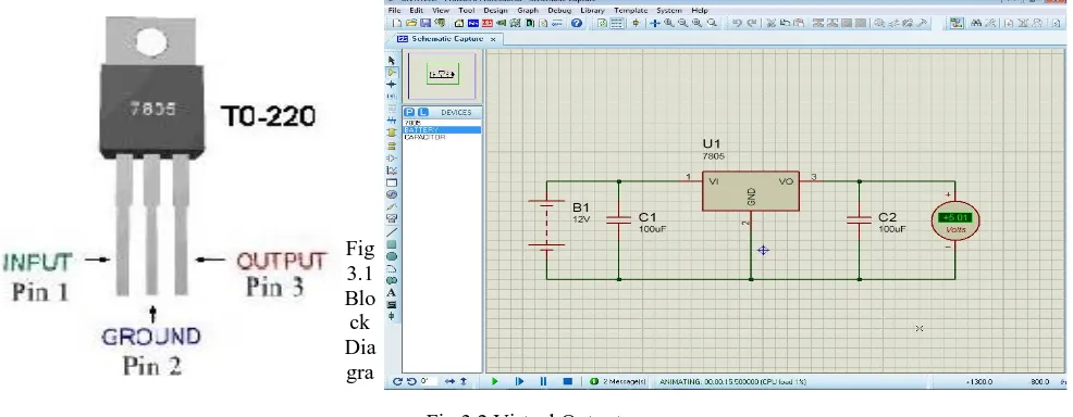
3.2.1 Voltage Regulation using 7805:
ISSN(Online): 2320-9801
ISSN (Print): 2320-9798
I
nternational
J
ournal of
I
nnovative
R
esearch in
C
omputer
and
C
ommunication
E
ngineering
(An ISO 3297: 2007 Certified Organization)
Vol. 4, Issue 4, April 2016
voltage source (the battery). The voltage regulator works best and will be most efficient when a clean DC signal is fed into it. We don't want any ac noise (ripple) imposed on the DC line voltage. The capacitor, in essence, acts as a bypass capacitor. It shorts the AC signal of the voltage signal (which is noise on the voltage signal) to ground and only the DC portion of the signal goes into the regulator. Virtual Output of Power Supply using Proteus:
Fig 3.1 Blo ck Dia gra
Fig 3.2 Virtual Output
The second capacitor, the 100nF ceramic capacitor, is hooked up after the voltage regulator. This capacitor is there again to filter out any noise or high-frequency (ac) signals that may be on the DC voltage line. The circuit begins at the 12-volt battery. This produces a voltage of 12 volts. The first capacitor, the ceramic 100nF, cleans up the signal if any (ac) noise is present on this. It shorts this noise to ground and allows the pure DC signal into the regulator. The regulator regulates this voltage down to 5 volts. After it comes out of the regulator, the other capacitor, the 100nF ceramic, cleans up any high-frequency or ac noise that may come out, again to produce a clean DC signal. Now this DC voltage, clean and crisp, is ready to power other elements in circuit like LM358, RF modules, encoder and decoder ICs etc.
3.2.2 LDR (Light Dependent Resistor) and resistor biasing For Comparator:
LDR changes its resistance according to the light which falls on it from opposite vehicle or car. Relation between intensity of light and resistance of LDR is: = / Now light intensity of 1000 LUX causes temporary blindness in eyes. Hence we substitute LUX=1000 in above equation.
On solving we get, = . Ohm
Now consider following voltage divider bias which is used in circuit:
3.2.3 COMPARATOR ACTION:
In electronics, a comparator is a device that compares two voltages or currents and outputs a digital signal indicating which is larger. It has two analog input terminals and and one binary digital output. The output is ideally
ISSN(Online): 2320-9801
ISSN (Print): 2320-9798
I
nternational
J
ournal of
I
nnovative
R
esearch in
C
omputer
and
C
ommunication
E
ngineering
(An ISO 3297: 2007 Certified Organization)
Vol. 4, Issue 4, April 2016
3.2.4 OPTOISOLATOR CIRCUIT:
PC817 requires normally 1V to turn on, that is pin 3 and pin 4 are made in contact with each other so that the collector emitter resistance decreases. When comparator output is high then it can easily drive PC817. Pin 4 is connected to logic 1 hence when comparator produces high output then pin 3 also gets logic 1. That’s working of this stage. We have used a pull downresistor not to take input of NOT gate into tristate by letting it unconnected when input of PC817 is logic 0. 3.2.5 Wiring Harness
ISSN(Online): 2320-9801
ISSN (Print): 2320-9798
I
nternational
J
ournal of
I
nnovative
R
esearch in
C
omputer
and
C
ommunication
E
ngineering
(An ISO 3297: 2007 Certified Organization)
Vol. 4, Issue 4, April 2016
Fig.3.4 Wiring Harness
By constricting the wires into a non-flexing bundle, usage of space is optimized, and the risk of a short is decreased. Since the installer has only one harness to install (as opposed to multiple wires), installation time is decreased and the process can be easily standardized. Binding the wires into a flame-retardant sleeve also lowers the risk of electrical fires.
3.2.6 Assembly Pictures:
IV.CONCLUSION AND FUTURE WORK
Headlamp glare is an issue that has grown in terms of public awareness over the past decade. This is caused due to the sudden exposure of our eyes to a very bright light; the bright headlights of vehicles in this case. This causes a temporary blindness called the Troxler effect. However too much light or improper lighting can result in glare. Glare occurs when visual field brightness is greater than the luminance to which the eyes are adapted. Glare is caused by both direct and indirect light Sources. Disability glare can be a major problem both in terms of the ability to see and visual comfort. Also it leads to annoyance, and fatigue.
ISSN(Online): 2320-9801
ISSN (Print): 2320-9798
I
nternational
J
ournal of
I
nnovative
R
esearch in
C
omputer
and
C
ommunication
E
ngineering
(An ISO 3297: 2007 Certified Organization)
Vol. 4, Issue 4, April 2016
no provision for switching the headlight beam of the vehicle, automatically. Hence an Automatic Headlight Beam Shifter could play a crucial role in shifting the headlights from driving beam to meeting beam and vice versa.
In the current tentative implementation of the Automatic Headlight Beam Shifter, we plan to include some improvements. Such as we can use some of the sensors along with the microcontroller to enhance the range of applications of this project
ACKNOWLEDGEMENT
We wish to express our deep gratitude and appreciation for the invaluable guidance of our professors throughout the span of preparing this seminar. We are indebted to our college Principal Dr.S.P.Bhosle.
We are also thankful to our HOD Dr.G.S.Sable for his precious and elaborate suggestions. His excellent guidance made us to complete this task successfully within a short duration. No thanks giving would be complete without mentioning our parents and family members (Brothers and Sisters), without their constant support and encouragement, this assignment wouldn’t have been successful. We also would like to express our humble gratitude for the invaluable help and support given by Mr S.B.Sharma (Head) & Mr. Yunus (Staff) of Chanakya Auto Electrical and Diesel services, Aurangabad.
Prof. BALAJI.B.WATTAMWAR RAGHAVENDRA.S.RAO MITHILESH.M.TIPKARI PRATIK.P.VYAS
REFERENCES
1. Automatic Headlight Dimmer a Prototype for Vehicles Muralikrishnan.R, IJRET: International Journal of Research in Engineering and Technology eISSN: 2319-1163 pISSN: 2321-7308
2. Electronic Head Lamp Glare Management System for Automobile Applications Sushil Kumar Choudhary , Rajiv Suman, Sonali, Honey Banga International Journal of Research in Advent Technology, Vol.2, No.5, May 2014 E-ISSN: 2321-9637
3. Driving into a cleaner future, Report of the conference Progress in Automotive Lighting 25-26 September 2001, Darmstadt University of Technology, Germany. Stephen E Jenkins BSc PhD Optical and Photometric Technology Pty Ltd. ClinExpOptom2002; 85: 4: 238-240 4. Automatic Light Beam Controller for driver assistance P. F. Alcantarilla · L. M.Bergasa · P. Jimenez · I. Parra · D. F. Llorca · M. A.
Sotelo · S. S. Mayoral Received: 25 May 2009 /Revised: 26 November 2010 / Accepted: 10 February 2011 © Springer-Verlag 2011, Machine Vision and Applications DOI 10.1007/s00138-011-0327-y
BIOGRAPHY
Prof Balaji B Wattamwar is currently an Associate Professor in Maharashtra Institute of technology, Dept. of E&TC, Aurangabad. He has a vast experience as an I/C Principal, Vice Principal & HOD (9 Years). He was also a Faculty Advisor for ISTE. He is also honored with the Best Teacher Award in the year 2000.
Raghavendra.S.Rao is currently a Final Year student in Maharashtra Institute of Technology, Dept. of E&TC, Aurangabad. He is also a RedHat Certified Professional and looks forward for opportunities implementing both Electronics & Open Source Technologies.
Pratik.P.Vyas is currently a Final Year student in Maharashtra Institute of Technology, Dept. of E&TC, Aurangabad. He is interested in VLSI and Embedded systems. He has Published a paper Titled “Misconceptions in Circular Motion” & has participated in robocon and other robotics related even