ISSN(Online): 2320-9801
ISSN (Print): 2320-9798
International Journal of Innovative Research in Computer
and Communication Engineering
(An ISO 3297: 2007 Certified Organization)
Website: www.ijircce.com Vol. 5, Issue 3, March 2017
Bus Announcement System for Amaurotics
Kalaivani.R
1, Luthubullah.S
1, Mahendran.S
1, Malarkodi.T
1, S.saraswathy
2UG
students, Department of ECE, K.S.Rangasamy College of Technology, Tiruchengode, Tamilnadu, India1 Assistant Professor, Department of ECE, K.S.Rangasamy College of Technology, Tiruchengode, Tamilnadu, India2ABSTRACT: This paper present design and implement bus alert system for visually impaired people based on microcontroller unit Arduino NANO with ZigBee and speed sensor. The blind people in the bus stop provide with the ZigBee unit which is recognized by ZigBee in bus and the indication is made in bus that the blind people is present in the bus stop. The blind people give the input about the place they want to travel through keypad. Then input is analyzed by Arduino and it send the signal to ZigBee in blind unit. The corresponding bus receive the signal by ZigBee in bus unit and send the bus number to transreceiver in blind. These bus number is converted to audio by voice IC APR 9600 and the bus number is announced through headphone and also displayed in LCD for normal people. Then the speed sensor continuously measures speed of wheel if the bus stopped at the bus stop, it send the signal to blind unit and converted to audio. This intimate bus stopped at stop. Then blind people take correct bus parked in front of them.
KEYWORDS: Arduino, Zigbee, voice IC, speed sensor
I. INTRODUCTION
The World Health Organization calculated that there are 285 million visually impaired people worldwide. Visually impaired persons can be blind or partially sighted people. They are facing lot of problems in day to day life. Especially to identifying correct bus to travel is the biggest problem in their life. There are many technologies used to solve this problem like GPS, RF module etc. But these are not more effective. This project is solution for this problem. This system give intimation for bus arrival as well as the bus stopped at the bus stop. So using this proposed system VIP can easily travel in public transport.
II. PROPOSED WORK
ISSN(Online): 2320-9801
ISSN (Print): 2320-9798
International Journal of Innovative Research in Computer
and Communication Engineering
(An ISO 3297: 2007 Certified Organization)
Website: www.ijircce.com Vol. 5, Issue 3, March 2017
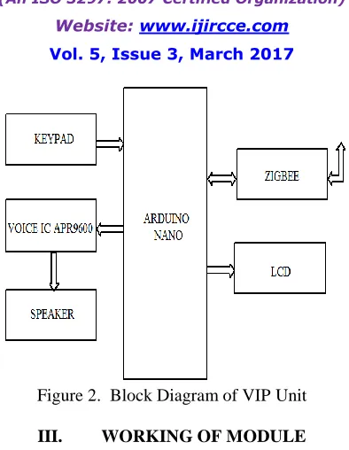
Figure 2. Block Diagram of VIP Unit
III. WORKING OF MODULE
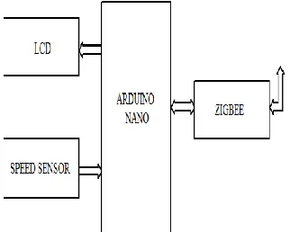
VIP MODULE
In this module, blind people press the bus number in keypad. It is connected to Arduino which sends signal corresponding to key pressing.
Afterwards the converted signal is passed to Zigbee transmitter. It transmits the relevant signal to Zigbee receiver through transmitting antenna.
BUS MODULE
ISSN(Online): 2320-9801
ISSN (Print): 2320-9798
International Journal of Innovative Research in Computer
and Communication Engineering
(An ISO 3297: 2007 Certified Organization)
Website: www.ijircce.com Vol. 5, Issue 3, March 2017
Figure 3. Flow Chart for Working
IV. HARDWARE USED
A.ARDUINO
ISSN(Online): 2320-9801
ISSN (Print): 2320-9798
International Journal of Innovative Research in Computer
and Communication Engineering
(An ISO 3297: 2007 Certified Organization)
Website: www.ijircce.com Vol. 5, Issue 3, March 2017
Figure 4. Hardware Architecture of Arduino NANO
B.ZIGBEE
The zigbee specification is 802.15.4. It operates in 2.4GHz (ISM) radio band the same band as 802.11b standard, Bluetooth, microwaves and some other devices. The ZigBee module is shown in figure 5. It is capable of connecting 255 devices per network. The specification supports data transmission rates of up to 250 Kbps at a range of up to 30 meters. It consumes less power. It employs either of two modes, beacon or non-beacon to enable the to-and-fro data traffic. Beacon mode is used when the coordinator runs on batteries and thus offers maximum power savings. It transmit the data periodically. While using the beacon mode, all the devices in a mesh network know when to communicate with each other. The non-beacon mode used when the coordinator is mains-powered. It transmit the data slowly compared to beacon mode.
Figure 5. ZigBee Module
C.VOICE IC APR 9600
ISSN(Online): 2320-9801
ISSN (Print): 2320-9798
International Journal of Innovative Research in Computer
and Communication Engineering
(An ISO 3297: 2007 Certified Organization)
Website: www.ijircce.com Vol. 5, Issue 3, March 2017
Figure 6. APR voice IC Module
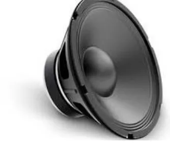
D.SPEAKER
A speaker is one of the most common output devices. It is a transducer which will convert electrical signal into sound. Figure 7 shown the image of speaker.
Figure 7. Speaker
E. LCD DISPLAY
ISSN(Online): 2320-9801
ISSN (Print): 2320-9798
International Journal of Innovative Research in Computer
and Communication Engineering
(An ISO 3297: 2007 Certified Organization)
Website: www.ijircce.com Vol. 5, Issue 3, March 2017
F. SPEED SENSOR
Speed sensor is used to detect the speed of an object, usually a transport vehicle. It is operated at the principle of anti-lock braking system. It has low speed measurement capability. Speed sensor is shown in figure 9.
Figure 9. Speed Sensor
V. SOFTWARE USED
ARDUINO SOFTWARE (IDE)
The Arduino Integrated Development Environment - or Arduino Software (IDE) contains a text editor for writing code, a message area, a text console, a toolbar with buttons for common functions and a series of menus. It connects to the Arduino and Genuino hardware to upload programs and communicate with them. The open-source Arduino Software (IDE) makes it easy to write code and upload it to the board. It runs on Windows and Linux. The environment is written in Java and based on Processing and other open-source software. This software can be used with any Arduino board.
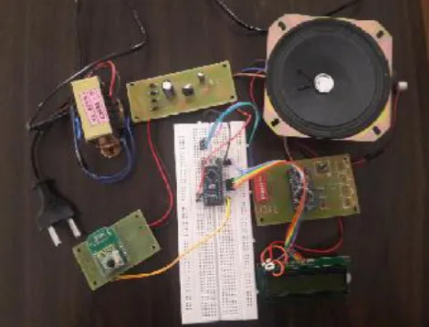
VI. RESULT
The figure 10shown the prototype output. Depending upon the input bus arrival and bus stopping at bus stop intimation is given to user.
ISSN(Online): 2320-9801
ISSN (Print): 2320-9798
International Journal of Innovative Research in Computer
and Communication Engineering
(An ISO 3297: 2007 Certified Organization)
Website: www.ijircce.com Vol. 5, Issue 3, March 2017
VII. CONCLUSION
This project developed with the welfare of the visually impaired in mind. This new prototype has many advantages which make it a good alternative to the current approaches. With this device, a whole life of those people will change and now they can contribute positively to their society and overcome their weaknesses related to the ability to move freely and without the help of anyone. Also, it is more economical and portable.
REFERENCES
[1] Majid Al Shamsi, Mahmoud Al-Qutayri, and Jeedella, “Blind Assistant Navigation System” in IEEE Transactions, March 2011.
[2]L. El Alamy, S. Lhaddad, S. Maalal, Y.Taybi, and Y. Salih-Alj, “Bus identification system for visually impaired person,” in 6th International Conference on Next GenerationMobile Applications, Services and Technologies (NGMAST), 2012, pp. 13–17, Sept 2012.
[3] Punitdharani, Benjamin Lipson, Devin Thomas,” Rfid Navigation System For Visually Impaired “, Project Advisor Professor Emmanuel April 25th, 2012.
[4] Mounir Bousbia-Salah, Abdelghani Redjati, Mohamed Fezari, Maamar Bettayeb, ―AN ULTRASONIC NAVIGATION SYSTEM FOR BLIND PEOPLE,‖ IEEE International Conference on Signal Processing and Communications (ICSPC 2007), pp.1003-1006.
[5] Kai Qin, Jianping Xing, Gang Chen, Linjian Wang, Jie Qin, "The Design of Intelligent Bus Movement Monitoring and Station Reporting System" Proceedings of the IEEE, International Conference on Automation and Logistics, China, 2008, pp. 2822-7. [6] Calder, David J.; Curtin .An obstacle signaling system for the blind ,Digital Ecosystems and Technologies Conference (DEST), 2011 Proceedings of the 5th IEEE International Conference on 30 June 2011.
[7] Hashino, S.; Ghurchian, R.; A blind guidance system for street crossings based on ultrasonic sensors. Information and Automation (ICIA)
[8] DIVYA, SRIRAMA, et al. (2010) Ultrasonic and voice based walking stick for the blind. Department of Electronics and Communication Engineering, Gokaraju Rangaraju Institute of Engineering and Technology.
[9] G.Gayathri, M.Vishnupriya, R.Nandhini and Ms.M.Banupriya, “Smart Walking Stick for visually impaired”, International Journal of Engineering and Computer Science, Vol.3, No.3, pp. 4057- 4061, March, 2014.