ISSN(Online): 2320-9801
ISSN (Print): 2320-9798
International Journal of Innovative Research in Computer
and Communication Engineering
(An ISO 3297: 2007 Certified Organization) Website: www.ijircce.com
Vol. 5, Issue 5, May 2017
Performance Evaluation of Neural Network
based Cognitive eNodeB in LTE Uplink
Rajat Urade
Master of Engineering Student, Dept. of E&TC, DYPCOE, Savitribai Phule Pune University, Pune, India
ABSTRACT: In this paper, a feed forward random neural network (RNN) with gradient descent (GD) and Levenberg Marquardt (LM) training algorithm based framework is used to improve inter cell interference coordination (ICIC) and radio resource management (RRM) in LTE system. A neural network based cognitive engine is embedded within eNodeB which co-ordinately suggest optimal radio parameters to the users, and best transmit power to the operating users by neighbouring cells. Long term learning, fast decision making , and less computational complexity are the three main requirements to map CE to distribute systematically in any cognitive communication system and most of the present techniques used as a cognitive solution lack in. The mechanism of feed forward network supported framework is examined with traditional schemes. To ensure a better performance of the system, the results are verified and compared with traditional schemes.
KEYWORDS: Energy Efficiency; Machine Learning; Random Neural Network; LTE uplink
I. INTRODUCTION
An unrivalled increase in the demand of mobile data access has been observed in the recent years. To deploy solution, 3rd Generation Partnership Project (3GPP) defined LTE system. Transmit power is one of the most important parameter in LTE uplink, which can communicate the problems comprises from channel fading, ICI, user equipment (UE) immoderate transmission power, and adjacent –channel interference (ACI). 3GPP deploy different solutions and techniques such as FPC for LTE uplink as an open loop power control (OLPC), which works on the assumption that interference generated towards other cells is generally because of cell-edge users However, corresponding interference ensue a different trend which affirm the assumptions that users experiencing the lowest path gain generate most of the interference is not always true [1]. This concludes that variations in the power will lead us to equilibrate the effect of generated interference, not by the path gain.
ISSN(Online): 2320-9801
ISSN (Print): 2320-9798
International Journal of Innovative Research in Computer
and Communication Engineering
(An ISO 3297: 2007 Certified Organization) Website: www.ijircce.com
Vol. 5, Issue 5, May 2017
A problem with traditional AI/ML techniques is retraining, which occurs in the situation in the process of exploitation while training CE, the radio may not be aware of the acceptable solutions to the actual problem, and this can consume additional time and energy. To avoid the process of retraining, the one must have to consider different operating environments while training CE, and for real time implementation it is difficult. If radio is operating in critical mission, there may not be enough time to retrain CE again and again. Accordingly, to severe change in environment, the long term learning is capable to avoid retraining.
Inadequacy of long term learning with fast decision making and less complexity having limiting factors of ANN and many other AI/ML conceptualizations. In [5] authors proposed Q-learning based collective interference control scheme and shown a structure which combined ANN and reinforcement learning (RL). Whereas, ANN go through limited generalization, slow calculation rate at run-time, local minima, and over-fitting problems. Stochastic-learning and proactive resource allocation based gradient algorithm for adaptive power control with the help of support vector regression is presented in [6]. In [7] a game theory based joint power and interference control framework for LTE-downlink is demonstrated. However, the system is having some limitations like it requires user specific utility parameters, which cannot be possibly taken in many situations [2].
It is found that the lack of study has been seen to achieve CE design features. The intrinsic properties of RNN, makes RNN a better choice for CE design [8]. In the previous work [9], authors presented the advantage of RNN over ANN with respect to their learning ability, complexity, and the generalization. In [10] the convergence speed and local minima problems of gradient descent (GD) based RNN by implementing genetic algorithm (GA), differential evolution (DE), and adaptive inertia weight particle swarm optimization (AIW-PSO) training algorithms. The real time comparison with different LTE environment has been demonstrated in the paper [11].
Therefore, our main efforts in this paper are: (1) Earlier RNN is used to improve the effect of ICIC and RRM in LTE uplink. In our work a new floor which helps to reduce the effect of ICI with zero bandwidth loss and collectively undertake both power and MCS selection has been introduced.
Earlier authors worked separately for the same contents. The changes in the system targets to program optimal transmit power and MCS to the attached user equipments (UEs) and also help to suggest satisfactory transmit power to the UEs served by neighbouring cells. The base station (BS) has power to control user specific power, thus to instruct mobile station (MS) to transmit power essential for uplink transmission , the channel quality information has to be sent by MS to the BS which is done by calculating optimal uplink transmit power level. (2) The proposed CE is evaluated with respect to the necessary requirements of CE design. In real time cases there can be training/retraining time restrictions, in that cases the proposed CR can check practicability and solidity. The training of CE is done with ANN and RNN datasets, where we contend ANN as a reference for RNN. (3) Levenberg marquardt (LM) and GD are used to minimize the cost function, while in previous work the there only focus is to consider GD (4) The comparison of the performance improvement in terms of training time and minimum square error of our proposed RNN with ANN is done. The organization of paper followed by Section 2, which introduces the field of study including system model, assumptions and calculations, scheduling, and CE design. In Section 3 a brief introduction of RNN has been given. Section 4 shows experimental results and discussion. Section 5 concludes the work and discussed future work.
II. FIELD OF STUDY
ISSN(Online): 2320-9801
ISSN (Print): 2320-9798
International Journal of Innovative Research in Computer
and Communication Engineering
(An ISO 3297: 2007 Certified Organization) Website: www.ijircce.com
Vol. 5, Issue 5, May 2017
into route discovery process. RREQ message will be forwarded when the nodes have sufficient amount of energy to transmit the message otherwise message will be dropped. This condition will be checked with threshold value which is dynamically changing. It allows a node with over used battery to refuse to route the traffic in order to prolong the network life. In [6] Authors had modified the route table of AODV adding power factor field. Only active nodes can take part in rout selection and remaining nodes can be idle. The lifetime of a node is calculated and transmitted along with Hello packets. In [7] authors considered the individual battery power of the node and number of hops, as the large number of hops will help in reducing the range of the transmission power. Route discovery has been done in the same way as being done in on-demand routing algorithms. After packet has been reached to the destination, destination will wait for time δt and collects all the packets. After time δt it calls the optimization function to select the path and send
RREP. Optimization function uses the individual node’s battery energy; if node is having low energy level then optimization function will not use that node.
A. Framework
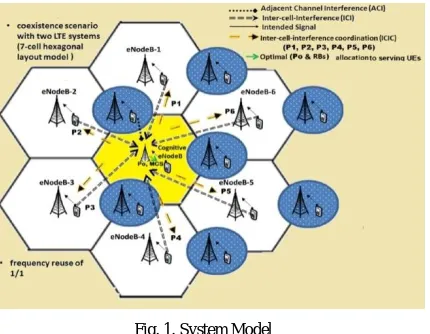
In LTE uplink, ICI which is considered as contact between resource blocks (RBs) [11], and to reduce the same power control strategy can be used. To verify the performance of the system, the basic LTE system has been used with 7 cell hexagonal layout having omnidirectional antennas at the centre of the corresponding cells, as shown in Fig. 1[11]. A RNN-CE has to deployed in the corresponding reference cognitive-eNodeB. MCS and power
p
0 are theconfiguration parameters of reference cell UEs and for adjacent eNodeB UEs, power (
p
1,p
2,p
3,p
4,p
5,p
6). Once C-enodeB is attached, it is responsible for monitoring, configuring UE, and also to manage radio resources. This is the phenomenon which has to be done for the implementation of the proposed system.B. Assumptions and calculations
As per 3GPPs LTE technical specification, the best we have taken to analyse the performance of LTE system. For the implemented system, the carrier frequency of the synchronic systems were set to 2000MHz for urban, suburban, and 900MHz for rural with inter-site distance of 750m. OFDMA urban macro propagation model is used. Antenna gains for BS and UEs were assumed to be 15dBi and 0dBi. 8 UEs per cell i.e. 24 RBs per BS and 3 per user were assumed. In addition, bandwidth of RB: 180 kHz; thermal noise density: -174dBm/Hz; system bandwidth: 10MHz; log-normal shadowing variance: 10dB with correlation; minimum coupling loss (MCL): 70dB; handover (HO) margin: 3 dB; BS noise figure: 5dB; UE min and max transmit power: -30dB dBm to 24 dBm were the system settings. The FPC settings, OFDMA LTE link to system level mapping, adjacent channel leakage ratio/unwanted spectrum mask were the same as given in Qualcomm STG(08) 13 and 3GPP technical specification [12].
Firstly, at the discrete speed value i.e. 0/3/30/100 kms./hr. Random positions of UEs were selected. Depending on the HO margin, path loss, antenna gain, and log normal fading, the UEs get attached to the most befitting BS. The quality of service (QOS) is having requirements; the connected UEs were scheduled for every iteration and allocate certain amount of resources. For the utility of MS, every BS goes through all MSs on its served mobile list and try to add their requested sub-carriers until all MSs are served.
The signal to noise interference noise ratio (SINR) and throughput for each UE with respect to link to system level mapping is determine as follows:
)
,
(
*
)
,
(
)
,
(
m
n
p
tm
n
pathloss
effectiveUE
m,nBS
mS
eq. (1)Where
S
(
m
,
n
)
is the received power atm
thserving C-eNodeB from then
th UE,p
tis the transmit power of UE indBm, and
pathloss
effective is the effective path-loss which considered MCL as defined in [11]. The bit rate for alluplink users is collected as follows:
MHz SINR
Hz bps sc total
UE SC
BW
x
N
N
rate
Bit
per
)
ISSN(Online): 2320-9801
ISSN (Print): 2320-9798
International Journal of Innovative Research in Computer
and Communication Engineering
(An ISO 3297: 2007 Certified Organization) Website: www.ijircce.com
Vol. 5, Issue 5, May 2017
Where SC UE
per
N
andN
totalscare the number of allocated sub-carriers to each UE and total number of sub-carriersavailable at each BS. The
Hz bps
x
is the spectral efficiency with respect to calculated SNIR andBW
MHzis the bandwidth.The combined ICI and ACI at reference cell is calculated as follows:
) (
) , ( ) , ( ) ,
(mn Iint mn I mn N thermal noise
I er ext t eq. (3)
Fig. 1. System Model
Where
I
inter(
m
,
n
)
is the ICI coming from the UEs of adjacent cells operating on same frequency sub-carriers and is calculated as follows:)
,
(
*
)
,
(
,, 1
int effeective ln m
N
m l l
t
er
p
l
n
pathloss
UE
BS
I
cell
eq. (4)
)
,
(
m
n
I
ext is the ACI coming from the UEs on adjacent channels in coexistent LTE system. ACI is the combination ofunwanted
I
(unwanted emission in adjacent band) andI
blocking(blocking effect of receiver) and is calculated as:
I
ext
iRSS
blocking(
UE
j,v,
BS
m)
*
iRSS
unwanted(
UE
j,v,
BS
m)
eq. (5)
C. Framework Planning
The aim is to achieve predicted SINR for the same, first C-eNodeB scheduler obtains particular UE, and alots RBs for uplink transmission, based on CQI and interference on scheduled RBs to accompanying transmission time interval, the embedded CE selects the optimal radio parameters (MCS and powers). Also the optimal transmit powers of UEs served by adjacent eNodeB will be suggested by CE. This process is depicted in Fig. 1 for 7 cell hexagonal layout.
D. CE Design
ISSN(Online): 2320-9801
ISSN (Print): 2320-9798
International Journal of Innovative Research in Computer
and Communication Engineering
(An ISO 3297: 2007 Certified Organization) Website: www.ijircce.com
Vol. 5, Issue 5, May 2017
for current CQI and aims, then the optimizer respond back to the learning module with considered C and M. The learning section provides the close performance of considered C and M i.e.
P
(
X
|
C
,
M
)
.To train CE, information which is available to cognitive controller can be categories as: environmental measurements (unwanted factors effecting the reliability of communication), configuration parameters (tuning parameters), and performance metric. To check the effect of configuration parameters and environmental parameters on the performance of the system, we train RNN with the same. All this parameters are justified in (1-5).
Environmental measurements (C): In this SINR, ICI, and ACI have been considered as environmental measurements.
Configuration parameters (C): Here the parameters such as available channels (RBs), transmit power
p
0,and MCS of all UEs served by C-eNodeB and the transmit powers (
p
1,p
2,p
3,p
4,p
5,p
6) of all UEs served by adjacent 6-eNodeBs. Performance metric: Expected throughput for each C-eNodeB UE as a performance measure is considered. The configuration parameters and environmental parameters are defined for input of the FFNN and the performance metric at the output of the FFNN. The input parameters are available at the respective cognitive eNodeB. Only one way communication/coordination between cognitive eNodeB to adjacent eNodeBs is required for scheduling process. With
a feature set C, label set M, and n training samples
T
((
x
1,
y
1),.,
(
x
n,
y
n))
(
XxY
)
n a ML algorithm creates a mappingA
:
X
Y
from features to labels for new samples.III. RANDOM NEURAL NETWORK
A RNN is mathematical representation of interconnected network of neurons or cells inspired by the spiking behaviour of biological neuronal networks. The inherent properties of RNN make it suitable for machine learning in CE. The main objective of the RNN is to transform the inputs into meaningful outputs, learn the input-output relationship, and offer viable solutions to unseen problems. RNN were first invented by Prof. Erol Galenbe [15] as a new modified class of ANNs. It offers more advantages and extemporize the limitations of ANN. In RNN, the neuron exchanges the signal in the form of spikes. The potential
(
k
)
of each neuron represents its state that increases/decreases with respect to an incoming signal. A neuronu
can receive positive/negative exogenous signals, modeled as Poisson arrival streams of rates
u and
u respectively. If a neuron receives an excitatory signal(
1
)
, its potential increases and correspondingly decreases upon receiving inhibitory signal(
1
)
. When the potential of neuronis equal to zero (
k
i= 0), it is in idle state and when (k
i> 0), the neuron is excited. In the state of excitation, the neuron fires an excitatory spike that goes from neuronu
tov
. In that case, the potential of neuronu
decreases by one, whereas potential of neuronv
increases by one. When neuron fires inhibitory spike, the potential of both neuron decreases by one. The firing is according to the Poisson process represented by the synaptic weightsw
i,j =rP
i,jand
j i
w
, =rP
i,j , whereP
i,j andP
i,j are the probabilities of excitatory and inhibitory signals and r is the spikes firingrate. The
w
i,j andw
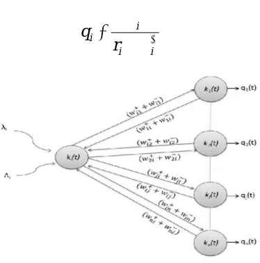
i,j can be seen as the positive and negative rates of signal transmissions and these are the typical interconnection weights of a neural network that RNN learns through the process of learning or training. A general model of RNN is shown in Fig. 6. The average arrival rate of
ive
and
ive
signals to neuroni
(
i)
andi
(
i)
, and the probability that neuroni
is excited(
q
i)
, are calculated using following equations:
nj j ij i
i 1
q
w
eq. (6)
i nj j iji
1q
w
ISSN(Online): 2320-9801
ISSN (Print): 2320-9798
International Journal of Innovative Research in Computer
and Communication Engineering
(An ISO 3297: 2007 Certified Organization) Website: www.ijircce.com
Vol. 5, Issue 5, May 2017
i i
i i
r
q
eq. (8)
Fig. 2. A feed forward random neural network framework
A. Network Behavior in Steady State
If
0
q
i
1
fori
1
,
2
,
3
...,
n
then stationary joint probability of networkp
(
k
,
t
)
p
r
[
k
(
t
)
k
]
can be written as:
n i
k i i
q
q
k
p
1
(
1
)
)
(
eq. (9)B. Network Stability
The network is stable, if the signal potential increases with bounds. Stability can be guaranteed if a unique solution to non-linear equations (6-8) exists. The existence of solution implies its uniqueness because for any neuron
i
, it is not possible to have two differentq
s. Moreover, in feed forward RNN, the solution always exists, sinceq
for every neuron is computed from the values of neurons on the preceding layer [12].C. RNN Training
The main purpose of training is to learn desired system behavior and adjust the network parameters (interconnections weights) to map (learn) the input output relationship and minimize the mean square error (MSE). The standard GD training algorithm, AIW-PSO, DE, and GA based leaning algorithms [10] was proposed earlier. However, in general there is trade off among learning accuracy, convergence time, calculation time, and computational complexity.
IV. SIMULATION RESULTS
A. Simulation Assumption
ISSN(Online): 2320-9801
ISSN (Print): 2320-9798
International Journal of Innovative Research in Computer
and Communication Engineering
(An ISO 3297: 2007 Certified Organization) Website: www.ijircce.com
Vol. 5, Issue 5, May 2017
B. CEs Training
The process of learning and the process of reasoning were the main computations to train CE. The decision making process is dependent on the process of learning; therefore the quality of decision making is completely dependent on the learning quality. To evaluate how well CE has learnt the system behaviour, MSE is used while training the CE; it also evaluates the performance of the learning process. Once, the system behaviour is learnt, the CE characterizes the achievable performance of possible actions i.e., the configuration parameters with respect to current situation, and then selects the most appropriate configuration parameters. The main aim of CE is achieve the least possible MSE in less training time.
C. Performance Gain
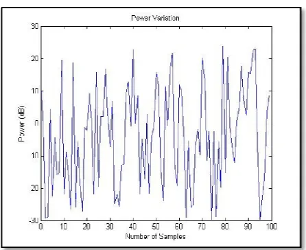
In training, different number of neurons, hidden layers and epochs were examined. The best performed RNN/ANN structures were 1 hidden layer with 11 neurons and 1 hidden layer with 20 neurons. Accordingly, In Fig. 3 we have shown the performance of the LTE system with respect to allotted UE and spotted eNodeBs. Fig. 4 shows the target achieved with greater accuracy accordingly with less time period with the help of a targeted mean square error at resulting epochs. Fig. 5, 6 shows the respective power variations in each eNodeB after training neural network.
Fig. 3. eNodeB and UE positions of LTE system Fig. 4. Target sector SINR CDF of LTE system
ISSN(Online): 2320-9801
ISSN (Print): 2320-9798
International Journal of Innovative Research in Computer
and Communication Engineering
(An ISO 3297: 2007 Certified Organization) Website: www.ijircce.com
Vol. 5, Issue 5, May 2017
Fig. 7. Power variations for 100 samples.
V. CONCLUSION AND FUTURE WORK
The performance of feed forward RNN over ANN has been evaluated in this paper, with reference to accuracy, and training time period, and under the same LTE environmental and configuration parameters. The feed forward RNN is used as a training algorithm for CE of eNodeB and the results shows that if feed forward RNN is used over ANN while training the CE, the learning time of the CE is reduced in such manner that the performance of the system will get increased as compared to traditional training algorithm. The best performance of the system is making a conclusion that the increasing number of neurons with 1 hidden layer having less time to reach the targeted mean square error. There are further advanced RNN techniques which we have not considered for the system. We believe the use of RNN for the real time application of CR problems will create better solutions.
REFERENCES
1. M. Boussif, N. Quintero, F. D. Calabrese, C. Rosa, and J. Wigard, “Interference based power control performance in lte uplink,” in Wire-less Communication Systems. 2008. ISWCS’08. IEEE International Symposium on. IEEE, 2008, pp. 698–702.
2. M. Bkassiny, Y. Li, and S. K. Jayaweera, “A survey on machine-learning techniques in cognitive radios,” Communications Surveys & Tutorials, IEEE, vol. 15, no. 3, pp. 1136–1159, 2013.
3. A. S. Hamza, S. S. Khalifa, H. S. Hamza, and K. Elsayed, “A survey on inter-cell interference coordination techniques in ofdma-based cellular networks,” Communications Surveys & Tutorials, IEEE, vol. 15, no. 4, pp. 1642–1670, 2013.
4. A. Attar, V. Krishnamurthy, and O. N. Gharehshiran, “Interference man-agement using cognitive base-stations for umts lte,” Communications Magazine, IEEE, vol. 49, no. 8, pp. 152–159, 2011.
5. A. Galindo-Serrano and L. Giupponi, “Distributed q-learning for ag-gregated interference control in cognitive radio networks,” Vehicular Technology, IEEE Transactions on, vol. 59, no. 4, pp. 1823–1834, 2010.
6. S. Deb and P. Monogioudis, “Learning based uplink interference man-agement in 4g lte cellular systems,” IEEE Transaction, arXiv preprint arXiv:1309.2543, 2013.
7. V. Poulkov, P. Koleva, O. Asenov, and G. Iliev, “Combined power and inter-cell interference control for lte based on role game approach,” Telecommunication Systems, vol. 55, no. 4, pp. 481–489, 2014.
8. S. Timotheou, “The random neural network: a survey,” The computer journal, vol. 53, no. 3, pp. 251–267, 2010.
9. A. Adeel, H. Larijani, and A. Ahmadinia, “Performance analysis of random neural networks in lte-ul of a cognitive radio system,” in 1st IEEE International Workshop on Cognitive Cellular Systems, IEEE CCS 2014, Rhine River, Germany, Sept 2-4, 2014.
10. Adeel, H. Larijani, A. Javed, and A. Ahmadinia, “Random neural network based power controller for inter-cell interference coordination in lte-ul,” in IEEE ICC 2015 Workshop on Advances in Software Defined and Context Aware Cognitive Networks, 2015.
11. A. Adeel, H. Larijani, and A. Ahmadania, “Random Neural Network based Cognitive eNodeB deployment in LTE Uplink," IEEE Global Communication Conference,San Diago, pp1-7, 2015.
ISSN(Online): 2320-9801
ISSN (Print): 2320-9798
International Journal of Innovative Research in Computer
and Communication Engineering
(An ISO 3297: 2007 Certified Organization) Website: www.ijircce.com
Vol. 5, Issue 5, May 2017
13. E. Gelenbe, “Random neural networks with negative and positive signals and product form solution,” Neural computation, vol. 1, no. 4, pp. 502– 510, 1989.
14. Gelenbe, “Learning in the recurrent random neural network,” Neural Computation, vol. 5, no. 1, pp. 154–164, 1993.
15. E. Gelenbe, “Random neural networks with negative and positive signals and product form solution,” Neural computation, vol. 1, no. 4, pp. 502– 510, 1989.
16. http://www.fon.hum.uva.nl/praat/manual/Feedforward_neural_networks_1__What_is_a_feedforward_ne.html, djmw, may 2004.
17. Gaikwad V., Sharma M. and Wagh T., “DTX Mechanism at Evolve Node for Efficient Power Saving in LTE Network,” International Journal of Wireless and Microwave Technologies, 5, 47-55, http://dx.doi.org/10.5815/ijwmt.2015.05.05.
BIOGRAPHY
Rajat Babanrao Urade is a Master of Engineering student in the Electronics and Telecommunication Engineering