University of Windsor University of Windsor
Scholarship at UWindsor
Scholarship at UWindsor
Electronic Theses and Dissertations Theses, Dissertations, and Major Papers
2018
Security-Aware RWA for Dynamic Traffic Using Path Protection In
Security-Aware RWA for Dynamic Traffic Using Path Protection In
WDM Networks
WDM Networks
Kamaljeet Singh Gill University of Windsor
Follow this and additional works at: https://scholar.uwindsor.ca/etd
Recommended Citation Recommended Citation
Gill, Kamaljeet Singh, "Security-Aware RWA for Dynamic Traffic Using Path Protection In WDM Networks" (2018). Electronic Theses and Dissertations. 7358.
https://scholar.uwindsor.ca/etd/7358
This online database contains the full-text of PhD dissertations and Masters’ theses of University of Windsor students from 1954 forward. These documents are made available for personal study and research purposes only, in accordance with the Canadian Copyright Act and the Creative Commons license—CC BY-NC-ND (Attribution, Non-Commercial, No Derivative Works). Under this license, works must always be attributed to the copyright holder (original author), cannot be used for any commercial purposes, and may not be altered. Any other use would require the permission of the copyright holder. Students may inquire about withdrawing their dissertation and/or thesis from this database. For additional inquiries, please contact the repository administrator via email
Security-Aware RWA for Dynamic Traffic
Using Path Protection In WDM Networks
By
Kamaljeet Singh Gill
A Thesis
Submitted to the Faculty of Graduate Studies through the School of Computer Science in Partial Fulfillment of the Requirements for
the Degree of Master of Science at the University of Windsor
Windsor, Ontario, Canada
2018
c
Security-Aware RWA for Dynamic Traffic Using Path Protection In WDM Networks
by
Kamaljeet Singh Gill
APPROVED BY:
E. Raheem
Department of Electrical and Computer Engineering
D. Wu
School of Computer Science
A. Jaekel, Advisor School of Computer Science
S. Bandyopadhyay, Co-Advisor School of Computer Science
DECLARATION OF ORIGINALITY
I hereby certify that I am the sole author of this thesis and that no part of this
thesis has been published or submitted for publication.
I certify that, to the best of my knowledge, my thesis does not infringe upon
anyones copyright nor violate any proprietary rights and that any ideas, techniques,
quotations, or any other material from the work of other people included in my
thesis, published or otherwise, are fully acknowledged in accordance with the standard
referencing practices. Furthermore, to the extent that I have included copyrighted
material that surpasses the bounds of fair dealing within the meaning of the Canada
Copyright Act, I certify that I have obtained a written permission from the copyright
owner(s) to include such material(s) in my thesis and have included copies of such
copyright clearances to my appendix.
I declare that this is a true copy of my thesis, including any final revisions, as
approved by my thesis committee and the Graduate Studies office, and that this thesis
ABSTRACT
Security and attack management have become the prime concern for the network
operators due to high data transfer rates and vulnerabilities associated with
trans-parency in WDM networks. In the recent years, there is a substantial increase in
perception to develop suitable mechanisms for subduing the adverse effects of
mali-cious attacks such as high power jamming and tapping attacks.In transparent optical
networks (TONs) traffic is carried over the optical fibers in the form of signals called
lightpaths, creating a virtual topology over the physical interconnections of an optical
fiber. This allows an exchange of an enormous amount of data at a very high speed.
A fault or an attack on the network can lead to data tampering and data loss. Unlike
faults, malicious attacks may not be localized and we cannot handle them with the
standard fault-tolerance mechanisms in WDM networks.
The Routing and Wavelength Assignment (RWA) problem assigns appropriate
routes and wavelengths to all associated lightpaths in the network. Most the
re-searchers considered the static traffic model, where the network requests (i.e.
light-paths to be established) are known in advance and last over long durations. In this
thesis, we are solving the security-aware problem for dynamic requests by using
pro-tection strategy known as dedicated path propro-tection (DPP). In the dynamic model,
lightpaths are generated on-demand, and RWA must be performed based on available
resources that are not being used by ongoing lightpaths. We propose an Integer linear
programming (ILP) formulation to maximize requests satisfaction and reducing the
DEDICATION
T o my loving f amily :
Grandmother : Surinder Kaur F ather: Balvinder Singh Gill
ACKNOWLEDGEMENTS
I would like to express my sincere gratitude to my supervisor Dr. Arunita Jaekel,
without him my thesis and my whole Master’s is incomplete. I also offer my
sin-cere appreciation to my co-supervisor Dr. Subir Bandyopadhyay for his continuous
support.
Secondly, I would also like to express my gratitude to my committee members Dr.
Esam Abdel-Raheem, and Dr. Dan Wu for their beneficial advice and suggestions for
TABLE OF CONTENTS
DECLARATION OF ORIGINALITY III
ABSTRACT IV
DEDICATION V
ACKNOWLEDGEMENTS VI
LIST OF FIGURES IX
LIST OF TABLES X
1 Introduction 1
1.1 Overview . . . 1
1.2 Motivation . . . 2
1.3 Solution Outline . . . 3
1.4 Thesis Organization . . . 4
2 Review of Optical Fiber Networks 5 2.1 Optical Components . . . 6
2.2 Optical network components . . . 7
2.2.1 Optical Multiplexer (MUX): . . . 8
2.2.2 Optical Demultiplexer (DEMUX): . . . 8
2.2.3 Optical add or drop multiplexer (OADM): . . . 8
2.2.4 Optical cross connect switch (OXC): . . . 9
2.3 Basic Concepts . . . 9
2.3.1 Wavelength Division Multiplexing (WDM) . . . 9
2.3.2 Routing And Wavelength Assignment (RWA) . . . 11
2.3.3 Traffic Models . . . 12
2.4 Attacks And Attack Management . . . 13
2.4.1 Attacks In Optical Networks . . . 13
2.5 Attack Management Techniques . . . 16
2.6 Literature Review . . . 19
3 Proposed Formulation For Attack-Aware RWA 22 3.1 Synopsis Of Proposed Model . . . 22
3.2 Proposed ILP Formulation For Dynamic Attack-Aware RWA (DAA-RWA) . . . 24
3.2.1 Notation: . . . 24
3.2.2 Input parameters: . . . 24
3.2.3 Variables: . . . 25
3.3 ILP Formulation (DAA-RWA) . . . 26
3.4 Justification of ILP Constraints . . . 30 3.5 An Illustrative Example . . . 32
4 Experiments And Results 36
4.1 Simulation Setup . . . 36 4.2 Blocking probability vs. Demand size . . . 39 4.3 Blocking probability vs. Channels . . . 41
5 Conclusion and Future Work 43
5.1 Conclusion . . . 43 5.2 Future Work . . . 44
REFERENCES 45
LIST OF FIGURES
2.1 Architecture of optical networks . . . 5
2.2 Basic structure of an optical fiber . . . 6
2.3 Multiplexer and demultiplexer . . . 8
2.4 Add drop explanation . . . 9
2.5 (a) Static and (b) Dynamic Optical Cross Connect Switch. . . 10
2.6 Wavelength Division Multiplexing . . . 11
2.7 Physical and Logical Topology . . . 12
2.8 Attack Aware Inband and Out-of-band. . . 15
2.9 Optical Amplifier(OA) . . . 15
2.10 Gain Competition in amplifiers . . . 16
2.11 Shared Path Protection . . . 17
2.12 Shared Path Protection . . . 18
3.1 6-node physical network topology . . . 23
3.2 Considering first adjacent channel . . . 24
3.3 Illustration of invalid Attack-aware RWA . . . 34
3.4 Illustration of valid Attack-aware RWA . . . 35
4.1 NSFNET network (14 - node topology) . . . 37
4.2 ARPANET network (20 - node topology) . . . 37
4.3 Example of a 4-node network and corresponding topology file [5] . . . 38
4.4 Comparison of blocking probabilities using different approaches . . . . 40
LIST OF TABLES
2.1 Summarizes all the papers we discussed under the current section. . 21
4.1 Blocking Probability vs. Demand Size - 14 nodes, 16 channels . . . . 39
4.2 Blocking Probability vs. Demand Size - 20 nodes, 16 channels . . . . 40
4.3 Blocking Probability vs. Demand Size - 40 nodes, 16 channels . . . . 40
4.4 Blocking probability vs number of channels in 14-nodes network with
20 demands . . . 41
4.5 Blocking probability vs number of channels in 20-nodes network with
20 demands . . . 42
4.6 Blocking probability vs number of channels in 40-nodes network with
CHAPTER 1
Introduction
1.1
Overview
The Internet is the global system of interconnected computer networks that use the
Internet protocol suite (TCP/IP) to link devices worldwide. It is a network of
net-works that consists of private, public, academic, business, and government netnet-works
of local to global scope, linked by a broad array of electronic, wireless, and optical
networking technologies. The Internet carries a vast range of information resources
and services, such as the inter-linked hypertext documents and applications of the
World Wide Web (WWW), electronic mail, telephony, and file sharing.. A
remark-able growth of internet traffic has been observed between the years 2000 to 2015,
calculated around 832.5% [21] . There is an urgent need of communication
mecha-nisms, which can help the users to access large amounts of data at high speeds and
also to improve the reliability of data transfers. Optical networks provide the ideal
infrastructure to handle this enormous growth [21].
Optical networks consist of optical fibers, which use signals encoded in the form
of light to transmit the information to various nodes into the network. Optical
com-munication provides robust, large capacity, high transmission rates over long
dis-tances with high-reliability transmission, interconnection, and management for the
multi-node networks. There are certain components on which optical networks rely,
1. INTRODUCTION
wavelength division multiplexing (WDM) technology.
Security is a major concern in communication systems. Furthermore, there are
some vulnerabilities associated with transparency in all-optical networks. Physical
layer attacks caused by the high-powered jamming signals can lead to data tampering
and can even result in loss of data. Techniques to reduce and limit the impact of such
attacks are an important research problem. In this thesis, we propose an attack-aware
routing and wavelength assignment (RWA) formulation to allocate resources in a safe
way to incoming communication requests.
1.2
Motivation
Transparent optical networks (TONs) are capable of accommodating with the rapid
increase and growing future traffic requirements. Transparency in the optical networks
leads to the high data communication without undergoing the opto-electro conversion.
One of the main advantages of the optical networks over the metal communication
networks is security. Still, there are several vulnerabilities aspects associated with
distinct devices used in the optical fiber technology that can lead to the attacks by
exploiting non- linearities such as crosstalk (in-band or out-of-band). It is possible
take advantages of these vulnerabilities and can carry out multiple attacks, breaching
the network acquiring an unauthorized access to the information flowing through the
optical fiber, which will compromise some key aspects of network and information
security (confidentiality, integrity, availability, non- repudiation network, and
infor-mation security). Some of the following recent attack attempts have been made on
the optical networks to gain unauthorized access to the data signals.
1. In 2003, Tapping a fiber optic cable without being detected, and making sense
of the information you collect certainly isn’t trivial, but has been done for the
1. INTRODUCTION
2. Eavesdropping case was reported in March 2003, The Wolf Report, Security
officials in the US discovered an illegally installed fiber eavesdropping device
in Verizons optical network. It was placed at a mutual fund company.shortly
before the release of their quarterly numbers [26].
3. On April 6, 2003, an illegal attempt was made to access the information from
the optical network in Baghdad- Fox News [26].
4. In 2005, Kimberllie Witcher noted in his research paper published by the SANS
Institute, that industry experts feel that it is as easy to hack a fiber optic cable
as a copper cable [28].
5. On 22nd June 2015, Pierluigi Paganini has written an article about Kevin
Mit-nick hacking an optical fiber data cable just by using an optical fiber clip-on
coupler [28].
This demonstrates how the attackers can take advantage of the vulnerabilities and
security threats related to the optical fiber networks. With the constant development
in the technology, equipment to breach the security of the networks are becoming
easily affordable and compact each day. Hence, there is need to develop a technology
to handle this kind of attacks on the optical fiber networks to provide the user a
secure and robust communication.
1.3
Solution Outline
In this thesis, we propose an integer linear program (ILP) formulation approach to
address the attack-aware RWA problem for dynamic traffic model, using dedicated
path protection (DPP) [5] in WDM optical network. A physical network is given,
which consists of the nodes and edges. Each edge is considered to be bidirectional,
1. INTRODUCTION
The RWA problem searches for the physical paths and available wavelengths, for
routing communication requests. In this thesis, we are considering both in-band and
out-of-band attacks, which will be explained in detail in Chapter 2. The main
ob-jective of the ILP formulation is to maximize the number of requests that can be
established in the network, by carrying out AA-RWA (attack-aware RWA) for each
request. Numerous simulation scenarios considering the different network
topolo-gies, demand sets, etc. are carried out to evaluate the performance of the proposed
approach.
1.4
Thesis Organization
The thesis is organized as follows: In chapter 2 an outline of different optical
network-ing components and fundamental concepts of WDM optical networks is presented, as
well a review of previous work on attack aware RWA in optical networks. Chapter
3 describes our proposed attack aware ILP for dynamic traffic using dedicated path
protection (DPP). In chapter 4, simulation results for the proposed ILP for different
standard topologies are discussed and analyzed. Finally, our conclusions, and some
CHAPTER 2
Review of Optical Fiber Networks
Communication industry, undergoing a change of communication medium i.e., to fiber
optic networks since its invention in early 1970s. This communication has become the
integral part of worlds communication technology because of its capability of carrying
data (tera bits per second) at high volume and speed by connecting different
conti-nents. Optical fiber shows a remarkable decrease in signal attenuation, distortion,
cost and increase in bandwidth capabilities. [19] [16] [8]
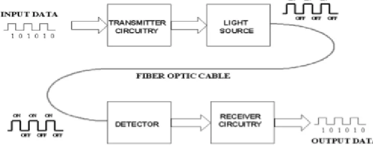
FIGURE 2.1: Architecture of optical networks
Figure [2.1] shows the basic architecture of an optical fiber network. There are
multiple components are used for opto-fiber communication [29]. Transmitter and
receiver are used to convert electrical signals to optical signals and vice versa, mostly
2. REVIEW OF OPTICAL FIBER NETWORKS
In all-optical networks, also called transparent optical networks (TONs), there is no
optical-electrical-optical (OEO) conversion at intermediate nodes.
2.1
Optical Components
In this section, we describe some of the main components used in optical networks.
Optical Fiber
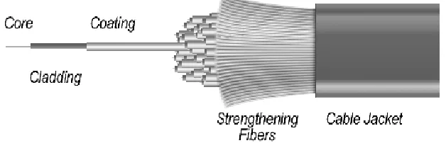
FIGURE 2.2: Basic structure of an optical fiber
An optical fiber is a thin glass strand which runs through the core of the cable
carrying the signals in the light pulses. The light pulse is injected into the strand from
one end of the optical fiber reaches to the other end with high speed and low
transmis-sion loss. The basic structure of the optical fiber consists of core, which carries actual
light signal, surrounded by cladding, a layer of glass with lower refractive index than
the core which is necessary for the phenomenon called total internal ref lection [25], protective buffer coating and strengthening fibers followed by the generic cable jacket,
acts as two protective layers which are shown in the figure [2.2]. While, the light signal
is injected into the core signal remain in the core throughout traversing from source
to destination leads to total internal reflection inside the cable.
Optical fibers are further classified into two major categories:
• Singlemodecable
2. REVIEW OF OPTICAL FIBER NETWORKS
Single mode cable consists of a single thread-like glass strand running through
the core of the cable with a diameter of 8.3 to 10 microns [24]. It generally carries
bandwidth higher than the multimode fiber. Single mode fiber is basically used in the
application which are required to carry multiple wavelengths with same mode so only
single cable is needed. Technically, in single mode we have multiple wavelengths of
light are used with same set of nodes having higher transmission rate and can carry
data 50 times more than multimode, and one drawback is high cost. In single mode
fiber it has much smaller core than multimode providing an advantage of no
distor-tion because of the small core and single ray of light propagating through the core
(signal degradation caused by light propagation of different frequencies at different
speeds) that could result from overlapping of light pulses and provides the least signal
attenuation (referred as loss of signal intensity) [2].
Multimode cable consist of a bit larger core diameter ranging between 50 to 100
micron, which is larger than single mode fiber [22]. It provides high bandwidth at high
speeds over medium distances, such as within a confined area like buildings, campus
providing data transfer speeds ranging from 10 Mbit/s to 10 Gbit/s over the link
lengths upto 600 meters (2000 feet ) [12]. Architects have switched to single mode
fiber in new applications using bandwidth in Gigabit and higher, due to multiple
rays of light, signal distortion occurs at the receiving end, results in an unclear and
incomplete data transfer in long distance cables [1].
2.2
Optical network components
In this section, a brief description of optical network components that are discussed in
this thesis is provided. The vulnerabilities associated with different optical networking
components lead to crosstalk during optical transmission [6]. These vulnerabilities
2. REVIEW OF OPTICAL FIBER NETWORKS
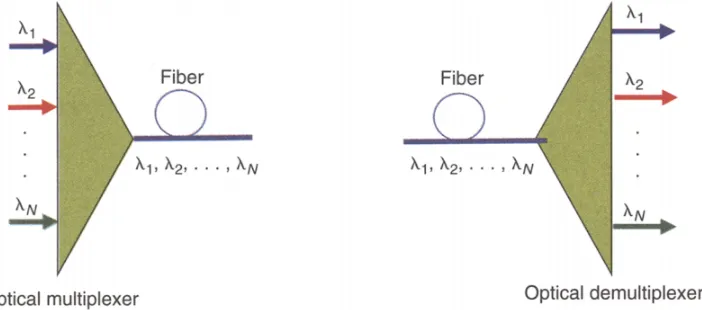
2.2.1
Optical Multiplexer (MUX):
Optical multiplexer is a device use to combine different wavelengths of light carrying
signals onto an optical fiber. It receives optical signals from several channels to merge
and couple them into one optical fiber [20]
2.2.2
Optical Demultiplexer (DEMUX):
Optical demultiplexer is a reverse multiplexer use to split the combined modulated
signal onto the different channels carrying signals [20].
FIGURE 2.3: Multiplexer and demultiplexer
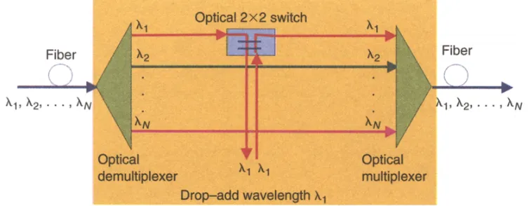
2.2.3
Optical add or drop multiplexer (OADM):
The optical add or drop multiplexer is a combined version of multiplexer and
demul-tiplexer, which selectively drops one or more channels carrying optical signals leaving
the channel empty. The OADM uses that empty channel and allocates it to another
incoming optical signal carrying data in the same direction of flow. These devices are
further divided into two categories namely, fixed or dynamic. The wavelength
selec-tion is static in these devices, between the optical DEMUX/MUX. In the dynamic
2. REVIEW OF OPTICAL FIBER NETWORKS
simple networks like ring and linear topologies, where traffic load is less.
FIGURE 2.4: Add drop explanation
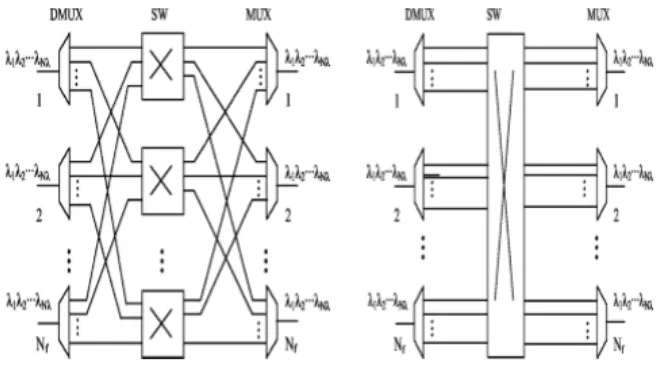
2.2.4
Optical cross connect switch (OXC):
The OXCs are another type of optical networking device, which connect optical
sig-nals between the output of DEMUX and the inputs of MUX in a single node. An
OXCs structure normally consist of MUXs, DEMUXs and optical switching fiber [7].
Routes through the switching fiber can be determined in two possible ways: static and
dynamic. In the static cross connect switch, the connections between the respective
DEMUXs and MUXs are fixed. In dynamic OXC, it is possible to modify the routing
of signals according to the requirement. As the switch ports are closely connected, it
is possible for the device to turn out to be a source of in-band crosstalk, where the
signals of same wavelength interact with each other.
2.3
Basic Concepts
2.3.1
Wavelength Division Multiplexing (WDM)
An optical fiber can handle a very large amount of data, around 50 terabits per
2. REVIEW OF OPTICAL FIBER NETWORKS
FIGURE 2.5: (a) Static and (b) Dynamic Optical Cross Connect Switch
cannot receive and transmit data at such highspeed. To overcome this bottleneck,
a new technique was introduced called wavelength division multiplexing, defined as:
wavelength division multiplexing (WDM) [4], is the idea of merging or multiplexing a
number of optical carrier wavelengths or signals onto a modulation signal on a single
fiber using channels traversed with different wavelength formats of light. [27]
In WDM networks, the bandwidth of a network is divided into multiple
non-overlapping ranges of frequencies called channels, where each channel corresponds
to a different carrier wavelength and is capable of sending data independently. The
wavelength division multiplexing method merges the data incoming from different
devices using different wavelengths and transmits them over single optical fiber, and
after traversing through the optical fiber at the receiving end, the wavelength division
multiplexing method splits the signals based on different carrier wavelengths and
routes them to their appropriate destinations [18].
When an optical signal traverse through the optical fiber, the signal quality and
strength degrades. It degrades in terms of amplitude, error bit rate, shape, and phase.
To overcome signal deterioration limitation amplifiers are used in the network.
2. REVIEW OF OPTICAL FIBER NETWORKS
bandwidth (tens of terahertz) that no existing opto-electronic sender or receiver device
can handle. Wavelength Division Multiplexing (WDM) addresses these problems by
dividing the bandwidth into several low speed channels (10 Gbits/s to 100 Gbits/s)
and reaching a high total data rate by combing several channels [13]
FIGURE 2.6: Wavelength Division Multiplexing
In the Figure [2.6], optical signals on individual channels (colors: purple, blue,
green and pink) are sent from respective transmitters (1 - 4) to be multiplexed and
traverse on a single optical fiber cable. And, at the receiver’s end they are
demulti-plexed and sent to respective receivers (5 - 8) to reach their appropriate destinations.
2.3.2
Routing And Wavelength Assignment (RWA)
The physical topology of an optical network consists of the set of nodes and the fiber
links that interconnect these nodes, as shown below in Figure [2.7]. A lightpath is
an all-optical connection established between two end nodes in the physical
topol-ogy, where the signal remains in the optical domain. A lightpath is unidirectional,
connecting a source node to a destination node, and can traverse multiple links in
2. REVIEW OF OPTICAL FIBER NETWORKS
physical topology. In the network, each lightpath is assigned a particular route and
carrier wavelength.
FIGURE 2.7: Physical and Logical Topology
The Routing and Wavelength assignment(RWA) problem is the act of
establish-ment of an effective route and assigning an available wavelength for the lightpaths in
an optical network. A feasible RWA assignment must satisfy the following constraints:
1. Wavelength Continuity Constraint: Each lightpath must use same assigned
wavelength on all traversed links from source to destination node.
2. Wavelength Clash Constraint: If two lightpaths are traversing through the
same link they must use distinct wavelengths.
2.3.3
Traffic Models
There are multiple ways of inputting the requested lightpath demands into the
2. REVIEW OF OPTICAL FIBER NETWORKS
Firstly, the static traffic model is a traffic model, where a set of source and
desti-nation pair communication links over the network are known in advance and mostly
there is no alteration over long durations. Most the researchers considered the static
traffic model as the demands remain comparatively steady for long periods of times
verified with other models. Such that the main objective of this model for this RWA
is to set-up as many requested lightpath demands as possible. The input for this
model is given in the form of matrix, providing number of connections to establish.
This model is mainly used in network planning and design phase.
Secondly, the dynamic model is generic to the other models, where the demand
lightpath request enter and leave the network at random time intervals. Moreover, the
duration of lightpath demand request is not known in advance. Mostly it is used to
enhance the resource utilization of the network, such as reallocation of the network
resources is possible in this model. The main objective of the online RWA traffic
model is to minimize the blocking probabilities. This method of injecting demands
into the network is used in the operation phase.
2.4
Attacks And Attack Management
2.4.1
Attacks In Optical Networks
Due to the high traffic transmission over the transparent optical networks, any kind of
failure or intentional attack can have a serious damage on the information traversing
over the network in form of data. Security and attack management are essential
part of the network confidentiality. In optical networks transparency is feature that
allows the routing and switching of data without conversion or regeneration of signal.
This is one of the core reasons that makes an attack undetectable and makes it
propagate deeper into the network having an serious impact on data in a transparent
2. REVIEW OF OPTICAL FIBER NETWORKS
optical network by allowing propagation of attack signals in the network. This kind
of opportunity creates a security breach used by the attackers to exploit the network
performance.
As compared to the link or node failure the attacks are much more difficult to
prevent and are more harmful for the network. A component failure affects the
lightpaths which are propagating through channels over the link while in case of an
attack many user and many parts of the network. The transparent optical networking
components considered most vulnerable to attacks are : the fiber, the amplifier and
the switch. An attack can be initiate by cutting or bending the fiber or can also be
considered as the component failure. Another type of attack is jamming attack is
caused when an attacker uses a legitimate channel and inject the high-powered signal
in the network. Further, this jamming signal leads to the crosstalk in the network
(interfere with other signals) in amplifiers and switches which leads to degradation
and service disruption.
Crosstalk is considered to be the most harmful type of attack because this type
of attack not only affect the attacked coonection but also has the ability to other
corresponding signals turning itself into a potential attacker.
Those external impairments are further divided into two as follows:
1. In-band(Intra-channel) crosstalk attack: When a high-powered attack
sig-nal is injected into the network using the same wavelength as of another sigsig-nal
and sharing a common node. The attacked signal may receive enough energy
from the attacking signal through the crosstalk, which makes it a potential
attacker for other signals.
2. Out-band(Inter-channel) crosstalk attack: When a high-powered attack
signal is injected into the network using the distinct wavelength as of another
en-2. REVIEW OF OPTICAL FIBER NETWORKS
ergy from the attacking signal through the crosstalk, which makes it a potential
attacker for other signals.
FIGURE 2.8: Attack Aware Inband and Out-of-band
Optical Amplifiers (QA), are normally used to amplify the signal that is attenuated
during the transmission process. One of the characteristics of an optical amplifier in
the network is gain competition. It is necessary that the signal remains in the optical
domain while traversing through the optical fiber, the signal needs proper gain in
order maintain the QoS. Erbium-doped Fiber Amplifiers are(EDFAs), are commonly
used operating at a wavelength region of 1550 nm, with the approximate gain of 35
nm.
FIGURE 2.9: Optical Amplifier(OA)
Suppose, the attacker injects a high-powered signal at carrier wavelength 1 (which
is usually varies from 20dB to 30 dB larger than the ideal user signal) into a
2. REVIEW OF OPTICAL FIBER NETWORKS
While traversing through the amplifier, as the amplifier can not distinguish
be-tween the attack signal and the legitimate network signals, attack signal can acquire
more energy and additionally amplify its power. As a result, channel 1 interfere with
channel 2 of power and further propagates down the network stream through the
suc-cessive optical components, affecting other adjacent channels in the optical network
along with propagation route and causing degrading or denying network service.
FIGURE 2.10: Gain Competition in amplifiers
2.5
Attack Management Techniques
To overcome the effects of attacks and faults in optical networks, two main
strate-gies are used: protection and restoration stratestrate-gies. In protection based approaches,
the backup resources are reserved in advance in case of any fault/attack, while in
restoration based approaches, spare backup resources are detected after diagnosing
the failure in the network.
Protection techniques are further divided into link protection or path protection.
In case of link protection, the backup paths and wavelengths are reserved for each link
of primary path. These reserved resources are used by all the lightpaths traversing
from the failure site including links, nodes etc or an attack. In the case of the path
protection scheme, a parallel path (backup lightpath) is reserved for each primary
2. REVIEW OF OPTICAL FIBER NETWORKS
Attack-Aware RWA consists of two approaches. The first approach attempts to
design the network topology and route the lightpaths in a manner where they do not
attack each other simultaneously. The second approach is based on path protection
which is further classified into two types:
• Shared P ath P rotection(SP P)
• Dedicated P ath P rotection(DP P)
1. Shared Path Protection (SPP): In this approach, concept behind this
pro-tection scheme is to share a backup channel among different, link/node diverse,
primary paths. In other words, one backup channel can be used to protect
various primary paths as shown on the figure below where the link between 1
and 3 is used to protect bothblue and purple color primaries. if corresponding
primary paths are link-disjoint.
FIGURE 2.11: Shared Path Protection
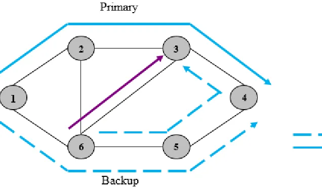
2. Dedicated Path Protection (DPP): In this approach, a separate backup
2. REVIEW OF OPTICAL FIBER NETWORKS
working or primary lightpath is being attacked by a high-powered signal at a
certain node or a certain link then the data transmitted over that path will be
interrupted, then the data will not reach its destination rightfully. Therefore, a
parallel lightpath (backup lightpath) is required that does not share resources
(like nodes or links) with the primary lightpath to isolate that attacked part
of the primary lightpath. The backup lightpath is utilized only if there is an
attack on the primary lightpath. DPP is easier to implement and test as well
as it is faster in the recovery process. For these reasons, this is the protection
scheme we are going to use in our research.
FIGURE 2.12: Shared Path Protection
In the figure [2.12] dedicated path protection primary and backup lightpath
should be edge-disjoint in the figure above distinct color are used for
differ-ent wavelengths, solid blue color and solid yellow line represdiffer-ents the primary
2. REVIEW OF OPTICAL FIBER NETWORKS
primary lightpath is being attacked by a high-powered signal at a certain node
or a certain link then the data transmitted over that path will be interrupted.
Then the backup lightpath will be used to accommodate the request that does
not share resources.
2.6
Literature Review
This section discusses relevant research for handling in-band and out-of-band jamming
attacks in optical fiber networks. These papers propose a broad range of solution
approaches, and are tested under different traffic topology, demand set and attack
scenarios.
In [17], the authors proposed the idea of routing the lightpaths in a network to
reduce the damage of an attack with additional cost. The authors proposed an ILP to
solve the problem for small networks to handle the out-of-band and in-band attacks.
For large networks they proposed a tabu search algorithm for attack-aware lightpath
routing, in combination with an existing graph-coloring algorithm for wavelength
assignment. The main objective of the this ILP is to minimize the Maximum
link-share attack radius (maxLAR). The secondary objective of this formulation is to
reduce the average load on the network.
The authors in [5] proposed a heuristic and added a new objective criterion for
the RWA problem to handle in-band attack propagation in all optical WDM networks
using dynamic demands traffic model. In this problem they have considered both
in-band and out-of-in-band attack propagation. They are considering interference on first
and second adjacent channels. They also consider the RWA problem with DPP.
In [11], the authors address the problem of routing and wavelength assignment
survivability. In this paper, the authors use the concept of Attack Group(AG) of
can-2. REVIEW OF OPTICAL FIBER NETWORKS
not be attacked by the same attacker signal. The authors use the concept of the
Attack Groups to enhance the existing survivability approaches. This concept is
utilized in combination with dedicated path protection(DPP) to develop an attack
aware DPP(AA-DPP). A two-step approach is proposed, which solves the routing
and the WA phases separately. The objective of the routing phase of AA-DPP-ILP,
is to minimize the number of attack-unprotected connections under the assumption
that an attack inserted on a working path can degrade any other working or backup
path if they share a common link. A heuristic is used to solve routing and
wave-length assignment problem for primary and backup paths. The author claims that
numerical results indicate that the proposed approaches provide dedicated path
pro-tection schemes with enhanced attack propro-tection without using more resources (i.e.,
wavelengths, average path lengths) than standard DPP methods.
In [9] the authors, discuss the problem of routing and wavelength assignment
sur-vivability. They combine the conventional survivability approach with the previously
proposed attack aware RWA to organise lightpaths in a way that reduces the
poten-tial damage from attacks [17] [7]. The goal is to make the protection paths valid for
attacks and not just link failures. The main focus of the work is implementing the
attack aware dedicated path protection scheme, considering that the backup paths
are calculated and reserved at lightpath setup time and resources may not be shared
among backup paths of different connections. The attack survivable RWA algorithm
is concerned about reducing the maximum potential damage from jamming attacks
by minimizing the objective wavelength usage the Attack Radius (AR), as well as
minimizing wavelength usage.
In [10], the authors state that conventional network survivability approaches
pro-tect transmission in case of the failures but do not provide good propro-tection from the
in-band or out-of-band jamming signal in the static environment since the primary
2. REVIEW OF OPTICAL FIBER NETWORKS
introduce a new protection scheme for jamming aware shared path protection
(JA-SPP) to achieve better survivability in the presence of attack signals in a resourceful
manner. In this paper, JA-SPP claims to protect against both single link failures
as well as high power jamming, with the same resource usage efficiency as standard
single link failure SPP with no jamming-awareness.
R.No. Reference Types of attacks Traffic Model Protection Scheme Solution Ap-proach [17] SkorinKapov,N., et al.2010 Out-of-band and Gain competition attacks
Static No ILP/Heuristic
[5]
Marcel El Soury et al. 2015
Out-of-band and In-band Attacks
Dynamic DPP Heuristic
[11]
Lena Wosinska
et al.2016 In-band Attack Static DPP ILP/Heuristic
[9]
Marija Furdek et al.2013
In-band and Out-of-band Attacks
Static DPP Heurstic
[11]
Nina Skorin-Kapov et al.2014
In-band and
Out-of-band Attacks Static SPP ILP
CHAPTER 3
Proposed Formulation For
Attack-Aware RWA
In this chapter, we are going to discuss our proposed approach for solving the attack
aware routing and wavelength assignment for dynamic traffic model, using dedicated
path protection. This chapter includes the detailed illustration and presentation of
the ILP formulation (including objectives, set of constraints) and other key features of
the solution. The main objective of the ILP formulation is to maximize the number
of successful requests in the network, while minimizing the path lengths of all the
primary and backup paths.
3.1
Synopsis Of Proposed Model
In our proposed model, the physical topology of the network is represented by a
directed graph Gp = (V p, Ep), where V p is the set of nodes and Ep is the set of edges. In this network each link is considered as bi-directional, which is implemented
by a pair of uni-directional links in the physical topology. Figure [3.1] shows an
example of a network topology with 6 nodes and 8 physical links (bi-directional).
There are multiple ways to handle the malicious spread of the high-powered
jam-ming signal in TONs. Major part of the research, considering attacks handling
3. PROPOSED FORMULATION FOR ATTACK-AWARE RWA
FIGURE 3.1: 6-node physical network topology
after experiencing an attack. In this thesis, the attack handling procedures are
incor-porated within the planning phase [6]. The thesis also takes into consideration the
fact that the interference and crosstalk between the channels sharing same link
de-creases as the channel spacing between their assigned channels inde-creases [18]. Hence,
the actual value of the channel spacing for which the crosstalk may be ignored
de-pends upon the number of factors such as the signal strength of the attacking and
attacked signal, the type of modulation used for sending out the signal onto the fiber
and the properties of the fiber [30].
Figure [3.2] shows a fiber with 5 available channels, numbered 1 to 5. If an
attacking signal is introduced on channel 3. It will attack lightpaths on adjacent
channels only (i.e. channel 2 and channel 4). However, signals on channels 1 and
5 will not be affected by this attack. We are considering this model approach in
our thesis and neglecting the second adjacent channels, as discussed in the previous
work the inference or leaking of the attacking signal to the second adjacent channel
3. PROPOSED FORMULATION FOR ATTACK-AWARE RWA
FIGURE 3.2: Considering first adjacent channel
3.2
Proposed ILP Formulation For Dynamic
Attack-Aware RWA (DAA-RWA)
In this section, we present the ILP formulation for the attack aware RWA for the
dynamic traffic model. Different constraints are proposed in order to reduce the
disruption in the network by malicious attacks (in-band and out-of-band attacks) for
the new and existing primary and backup lightpaths.
3.2.1
Notation:
The following notation are used in the proposed ILP formulation.
3.2.2
Input parameters:
• A physical topology G[N, A].
• N : Set of nodes.
• A : The set of all edges (physical fiber links) between the nodes of the network.
• C : Set of channel numbers.
3. PROPOSED FORMULATION FOR ATTACK-AWARE RWA
• M : A large constant.
• ac,ki,j : A constant for channel c∈C on edge (i, j)∈A and primary lightpath k
such that 1 if channel con edge (i, j)∈A is used by thekth primary lightpath,
0 otherwise.
• pc,ki : A constant for channel c∈ C, node i ∈ N and primary lightpath k such that 1 if the kth primary lightpath uses nodei∈N and channelc, 0 otherwise.
• bc,ki,j : A constant for channel c ∈ C on edge (i, j) ∈ A and communication k
such that 1 if channel con edge (i, j)∈A is used by thekth backup lightpath,
0 otherwise.
• qc,ki : A constant for channel c ∈ C, node i ∈ N and backup lightpath k such that 1 if the kth backup lightpath uses nodei∈N and channel c, 0 otherwise.
• S : Source node of request.
• D : Destination node of request.
3.2.3
Variables:
• xi,j : A binary variable denoting whether the path chosen for the primary
lightpath uses edge (i, j)∈A, wherexi,j = 1, if the path chosen for the primary
lightpath uses edge (i, j)∈A, 0 otherwise.
• yi,j : A binary variable denoting whether the path chosen for the backup
light-path uses edge (i, j) ∈ A, where yi,j = 1, if the path chosen for the backup
lightpath uses edge (i, j)∈A, 0 otherwise.
• ωc : A binary variable denoting the channel used for the primary lightpath such that ωc = 1, if the primary lightpath for the new connection request uses
3. PROPOSED FORMULATION FOR ATTACK-AWARE RWA
• νc: A binary variable denoting the channel used for the primary lightpath such
thatνc= 1, if the backup lightpath for the new connection request uses channel
c, 0 otherwise.
• γc
i,j : A continuous variable where the value lies between 0 and 1, γi,jc = 1, if
the new primary lightpath uses channel cand edge (i, j)∈A, 0 otherwise.
• δci,j : A continuous variable where the value lies between 0 and 1, δci,j = 1, if the new backup lightpath uses channel c and edge (i, j)∈A, 0 otherwise.
• R1k: A binary variable whereR1k = 1, if the new primary lightpath may attack
the kth primary lightpath, 0 otherwise.
• S1k: A binary variable whereS1k = 1, if the new primary lightpath may attack
the kth backup lightpath, 0 otherwise.
• R2k : A binary variable whereR2k= 1, if the new backup lightpath may attack the kth primary lightpath, 0 otherwise.
• S2k: A binary variable whereS2k = 1, if the new backup lightpath may attack
the kth backup lightpath, 0 otherwise.
• s : A binary variable where s = 1, if the request for a connection may be satisfied, 0 otherwise.
3.3
ILP Formulation (DAA-RWA)
3.3.1
Objective function
Maximize
M ·s− X
(i,j)∈A
xij −
X
(i,j)∈A
3. PROPOSED FORMULATION FOR ATTACK-AWARE RWA
Satisfy the flow-balance equations for the primary and the backup lightpaths:
X
j:(i→j)∈A
xij −
X
j:(j→i)∈A
xji =
s if i=S
−s if i=D,i∈N,
0 otherwise.
(1)
X
j:(i→j)∈A
yij −
X
j:(j→i)∈A
yji =
s if i=S
−s if i=D,i∈N,
0 otherwise.
(2)
Primary and backup paths must be edge disjoint
xi,j+yi,j ≤1 ∀(i, j)∈A (3)
Wavelength continuity constraints
X
c∈C
ωc =s ∀c∈ C (4a)
X
c∈C
νc=s ∀c∈ C (4b)
ωc+νc ≤1 ∀c∈ C (4c) Define γc
i,j and δi,jc
Υcij ≤ωc ∀(i, j)∈A,∀c∈ C (5a)
3. PROPOSED FORMULATION FOR ATTACK-AWARE RWA
Υcij ≥ωc+xij −1 ∀(i, j)∈A,∀c∈ C (5c)
δijc ≤νc ∀(i, j)∈A,∀c∈ C (6a)
δcij ≤yij ∀(i, j)∈A,∀c∈ C (6b)
δijc ≥νc+yij−1 ∀(i, j)∈A,∀c∈ C (6c)
Wavelength clash constraints
Υcij +X
k∈K
ackij +X
k∈K
bckij ≤1 ∀(i, j)∈A,∀c∈ C (7a)
δijc +X
k∈K
ackij +X
k∈K
bckij ≤1 ∀(i, j)∈A,∀c∈ C (7b) Set R1k = 1, if new primary lightpath may attack kth existing primary lightpath
R1k ≥Υcij ·pcki ∀(i, j)∈A,∀k ∈K,∀c∈ C (8a)
R1k≥ΥciD·pckD ∀(i, j)∈A,∀k ∈K,∀c∈ C (8b)
R1k ≥Υcij ·(aij(c−1)k+aij(c+1)k) ∀(i, j)∈A,∀k∈K,∀c∈ C (8c)
R1k≤ X
(i,j)∈A
X
c∈C
3. PROPOSED FORMULATION FOR ATTACK-AWARE RWA
Set S1k = 1, if new primary lightpath may attack kth existing backup lightpath
S1k≥Υcij ·qick ∀(i, j)∈A,∀k ∈K,∀c∈ C (9a)
S1k ≥ΥciD·qDck ∀k∈K,∀c∈ C (9b)
S1k ≥Υcij ·(bij(c−1)k+bij(c+1)k) ∀(i, j)∈A,∀k ∈K,∀c∈ C (9c)
S1k≤ X
(i,j)∈A
X
c∈C
Υcij·[(b(ijc−1)k+bij(c+1)k) +qick+qckD] ∀k ∈K (9d) Set R2k = 1, if new backup lightpath may attack kth existing primary lightpath
R2k ≥δijc ·pcki ∀(i, j)∈A,∀k∈K,∀c∈ C (10a)
R2k≥δiDc ·pckD ∀(i, j)∈A,∀k ∈K,∀c∈ C (10b)
R2k ≥δijc ·(aij(c−1)k+aij(c+1)k) ∀(i, j)∈A,∀k∈K,∀c∈ C (10c)
R2k ≤ X
(i,j)∈A
X
c∈C
δijc ·[(a(ijc−1)k+aij(c+1)k) +pcki +pckD] ∀k ∈K (10d) Set S2k = 1, if new backup lightpath may attack kth existing backup lightpath
S2k ≥δcij ·qick ∀(i, j)∈A,∀k ∈K,∀c∈ C (11a)
3. PROPOSED FORMULATION FOR ATTACK-AWARE RWA
S2k ≥δijc ·(bij(c−1)k+bij(c+1)k) ∀(i, j)∈A,∀k ∈K,∀c∈ C (11c)
S2k≤ X
(i,j)∈A
X
c∈C
δcij·[(b(ijc−1)k+bij(c+1)k) +qcki +qckD] ∀k ∈K (11d) If the new primary lightpath attacks any existing primary lightpaths, it must not
attack the corresponding existing backup lightpaths.
R1k+S1k ≤1 ∀k ∈K (12) If the new backup lightpath attacks any existing primary lightpaths, it must not
attack the corresponding existing backup lightpaths.
R2k+S2k ≤1 ∀k ∈K (13) If the kth existing primary lightpath attacks the new primary lightpaths, it must not attack the corresponding new backup lightpath.
R1k+R2k ≤1 ∀k ∈K (14) If the kth existing backup lightpath attacks the new primary lightpaths, it must
not attack the corresponding new backup lightpath.
S1k+S2k ≤1 ∀k ∈K (15)
3.4
Justification of ILP Constraints
The objective function of the ILP formulation is to maximize the number of requests
3. PROPOSED FORMULATION FOR ATTACK-AWARE RWA
for each request. In our objective we used M which is a large constant multiplied
with s request satisfying binary variable, the value will be 1, if the corresponding
request for a connection is satisfied, otherwise the value will be 0. The constraints
(1)-(2)are the flow balance, basic routing and wavelength assignment constraints for
primary and backup lighpaths. The constraints (1-2) are the traditional flow
con-servation constraints that allocate a feasible route to the lightpath over the physical
topology. The constraint (3) is the edge disjoint constraint, ensuring that the new
primary lightpath and the new backup lightpath do not have any common edges.
The constraint (4a)-(4c) enforces the wavelength continuity constraint for the new
primary (backup) lightpath. This ensures that the same wavelength c is allotted to the lightpath throughout its route. The constraints(5a)-(5c)compute the continuous
variable γc
i,j such that γi,jc = 1 if the new primary lightpath uses channel cand edges
(i, j) ∈ A. Similarly, the constraints (6a)-(6c) compute the continuous variable δci,j
such that δi,jc = 1 if the new backup lightpath uses channel c and edges (i, j) ∈ A. The constraints (7a)-(7b) are wavelength clash constraints. The constraint(7a)-(7b)
states that a channelcon edge (i, j)∈Acan be used by the primary (backup) light-path of the new request only if it is not currently allocated to any existing primary
or backup lightpath.
The constraints(8a)-(8d)are attack aware constraints. The constraints(8a)-(8d)
set the value of R1k = 1 if the new primary lightpath is capable of attacking the
kth existing primary lightpath and vice versa. The constraints(8a)-(8b) are used to address the case of in-band attacks, and set R1k = 1 if the new primary lightpath and the kth existing primary lightpath both use the same wavelength c and share a
common nodei. The constraint(8c)is for out-of-band attack in the network and sets the value of R1k = 1 if the new primary lightpath and kth primary lightpath share a
3. PROPOSED FORMULATION FOR ATTACK-AWARE RWA
and the kth primary lightpath uses channel c+ 1 or c−1. Finally, constraint (8d)
ensures that the value of R1k is set to 0 if none of the conditions of in-band and
out-of-band attacks are between the new primary lightpath and kth existing primary
lightpath are not satisfied, i.e. they are not able to attack each other.
Constraints (9a)-(9d) are similar to constraints (8a)-(8d), but are used to
deter-mine if the new primary lightpath is capable of attacking the kth existing backup
lightpath and vice versa. If so, the value of S1k is set to 1, and 0 otherwise. In a similar manner, constraints (10a)-(10d) ((11a) - (11d)), are used to determine if
the new backup lightpath is capable of attacking the kth existing primary (backup)
lightpath and vice versa. If so, the value of R2k (S2k) is set to 1, and 0 otherwise.
The constraint (12) ensures that it is not possible for the new primary lightpath
to attack both thekth existing primary and backup lightpaths at the same time (i.e.,
the kth existing primary and backup lightpaths are not within the reach of the same attacker).
The constraint (13) ensures that it is not possible for the new backup lightpath
to attack both thekth existing primary and backup lightpaths at the same time (i.e.,
the kth existing primary and backup lightpaths are not within the reach of the same
attacker).
The constraint (14) ensures that it is not possible for the kth primary lightpath
to attack both the new primary and backup lightpaths at the same time. Finally,
constraint (15) ensures that it is not possible for the kth bakcup lightpath to attack both the new primary and backup lightpaths at the same time.
3.5
An Illustrative Example
An illustrative example is discussed in this section in order to explain the proposed
3. PROPOSED FORMULATION FOR ATTACK-AWARE RWA
order to support each connection request between a pair of source and destination
nodes. The first is the primary path or working path and the other is known as
backup lightpath. The backup lightpath is not used unless the primary lightpath is
disrupted, either due to a fault in the network or an attack.
Figure 3.3 shows 2 connections established over a 6-node physical topology. r1w
and r1b (r2w and r2b) are the primary and backup lightpaths of the first (second)
connection respectively. r1w and r1b use routes 0 → 2 → 5 and 0 → 1 → 4 → 5
and are assigned channels λ1 and λ2 respectively. r2w and r2b use routes 1 →4 and
1→0→2→5→4 and are assigned channels λ3 and λ2 respectively.
This means that r2b can attack r1w using out-of-band attack, since they are
as-signed adjacent channels on a common link 2 →5. Moreover, r2b, it can also attack
(using in-band attack) lightpath r1b, as they are using a common channel λ2 and
traversing the same nodes (at nodes 0, 1, 4 and 5). This violates constraint(13) and
therefore is not a valid attack-aware RWA.
On the other hand, if we assign wavelength λ4 for lightpath r1w then, r2b can
no longer attackr1w, since the two lightpaths are no longer using adjacent channels.
3. PROPOSED FORMULATION FOR ATTACK-AWARE RWA
3. PROPOSED FORMULATION FOR ATTACK-AWARE RWA
CHAPTER 4
Experiments And Results
In this chapter we present our simulations and discuss the results for different network
topologies. We compare the performance of our proposed approach (DAA-RWA),
outlined in Chapter 3, with the with the following two approaches:
• A full attack-aware RWA approach using dedicated protection (AA-DPP) [9]
• An attack-unaware RWA approach that minimizes the number of wavelength
links (AU-RWA)
The main objective is to minimize the blocking probabilities. The proposed
ILP can generate optimal results for practical sized problems, using the IBM ILOG
CPLEX 12.6.2 optimization studio [13]. The blocking probability is a measure of the
probability that an incoming call request will be denied. It depends on factors such
as offered traffic, network resources and connection control algorithms. The blocking
probability can be used as a metric for evaluation of various protection schemes. A
scheme which has a lower blocking probability makes better utilization of the network
resources. An increase in number of set up requests means a decrease in the lightpath
blocking probability, therefore a better network performance [14].
4.1
Simulation Setup
4. EXPERIMENTS AND RESULTS
1. The 14-node NSFNET shown in Fig 4.2 [3],
2. The 20-node ARPANET network shown in Fig 4.3 [3]
3. A 40-node synthetic network topology
FIGURE 4.1: NSFNET network (14 - node topology)
FIGURE 4.2: ARPANET network (20 - node topology)
The links between two nodes in each physical topology are assumed to be
4. EXPERIMENTS AND RESULTS
8,16 or 32 channels. The network layout or topology is defined by the network
topol-ogy file. This information is supplied in the form of a table of size N xN, where N is the number of nodes in the network. In the table, if the value in row iand column j
is 1(0), it means there is a link (there is no link) between node i and nodej. Figure 4.3 illustrates the structure of the topology file .
FIGURE 4.3: Example of a 4-node network and corresponding topology file [5]
After reading the network topology, we input the demand file. The demand file
consists of a set of demands to be established over the network. Each demand consists
of a source and destination node, which are randomly generated. The number of
demands in a demand file ranges between 20 105 demands. The demands are given
as input to the ILP one by one. The ILP attempts to find a feasible primary lightpath
and backup lightpath for each demand. Two possible cases are considered:
1. If a demand is successfully allocated, the assigned routes and channels are used
to update the databases, which contain information about routes of each
estab-lished connection. This information is used when trying to accommodate the
next request, to ensure both primary and backup lightpaths are not
4. EXPERIMENTS AND RESULTS
2. If feasible primary and backup lightpaths could not be allocated, the demand
is considered blocked and contributes to the blocking probability. In this case,
there is no need to update the corresponding databases, before trying the next
demand.
4.2
Blocking probability vs. Demand size
Tables 4.1, 4.2 and 4.3 show how the blocking probability varies when the traffic
load is varied for different topologies, with 16 channels per fiber. The number of
demands for the first 2 networks varied from 20 - 35 demands, while for the 40-node
network the number of demands varied from 90 - 105 demands. The Attack-Unaware
DPP (AU-DPP) represents the traditional DPP algorithm, which does not consider
potential attacks. In AU-DPP, a connection is never blocked due to vulnerability to
attacking lightpaths; it can only be blocked due to unavailability of suitable channels
to route the corresponding working and backup lightpaths, due to network congestion.
Therefore, in all these simulations, we expect that the AU-DPP approach will have the
best performance, and is included as a reference point to evaluate the other approach.
As expected, the blocking probability in general increases with the requests.
Blocking Probability Traffic Load 20 25 30 35
Approach
AA-DPP 1.25 7 11.66 18.57
AU-DPP 0 0 0 0
DAA-RWA 0 0 0 0
TABLE 4.1: Blocking Probability vs. Demand Size - 14 nodes, 16 channels
For all topologies, the results indicate that the blocking probability of AA-DPP[9]
approach is higher than our approach and the attack-unaware approach for all
4. EXPERIMENTS AND RESULTS
AU-DPP for low traffic loads. As the traffic load increases, the difference in blocking
probability between AU-DPP and the proposed approach becomes more noticeable.
However, the proposed approach still consistently performs better that AA-DPP[9].
Blocking Probability Traffic Load 20 25 30 35
Approach
AA-DPP 0 0 0.83 2.14 AU-DPP 0 0 0 0 DAA-RWA 0 0 0 0
TABLE 4.2: Blocking Probability vs. Demand Size - 20 nodes, 16 channels
Blocking Probability Traffic Load 90 95 100 105
Approach
AA-DPP 58.61 60.52 61.75 62.85 AU-DPP 25.56 29.47 33 36.19 DAA-RWA 31.11 34.04 36.33 38.41
TABLE 4.3: Blocking Probability vs. Demand Size - 40 nodes, 16 channels
4. EXPERIMENTS AND RESULTS
Figure 4.5 compares the blocking probability the different approaches in the
40-node network for different traffic loads. As, expected, blocking probability of our
proposed approach is more than the blocking probability of AU-DPP. However, the
proposed approach still consistently performs better that AA-DPP[9].
4.3
Blocking probability vs. Channels
In this section, we study how the blocking probability varies with the number of
avail-able channels per fiber. Tavail-ables 4.4, 4.5 and 4.6 represent the blocking probability of
14-nodes, 20-nodes, and 40 nodes network using fibers with 8, 16 and 32 channels.
The three tables show that the blocking probability of AA-DPP[9] consistently
ex-ceeds all the other approaches. The performance of our proposed approach is very
close to that of AU-DPP, particularly when the network is less congested (i.e. more
available channels per fiber). As the network congestion increases, the performance of
the proposed approach degrades somewhat compared to AU-DPP, but is still better
than AA-DPP. For all three approaches, the blocking probability decreases when the
number of channels per fiber increases.
Blocking Probability Channels per fiber 8 16 32
Approach
AA-DPP 33.75 1.25 2.5
AU-DPP 0 0 0
DAA-RWA 13.33 0 0
TABLE 4.4: Blocking probability vs number of channels in 14-nodes network with 20 demands
Fig. 4.6 shows that the blocking probability of the AA-DPP approach exceeds
the blocking probability of the proposed approached tested with different number of
4. EXPERIMENTS AND RESULTS
Blocking Probability Channels per fiber 8 16 32
Approach
AA-DPP 13.75 0 0
AU-DPP 0 0 0
DAA-RWA 5 0 0
TABLE 4.5: Blocking probability vs number of channels in 20-nodes network with 20 demands
Blocking Probability Channels per fiber 8 16 32
Approach
AA-DPP 77.78 58.61 28.32 AU-DPP 62.22 26.56 0 DAA-RWA 65.56 32.59 0
TABLE 4.6: Blocking probability vs number of channels in 40-nodes network with 90 demands
CHAPTER 5
Conclusion and Future Work
5.1
Conclusion
In this thesis, we propose an integer linear program (ILP) formulation approach to
address the attack-aware RWA problem for dynamic traffic model [15], using dedicated
path protection (DPP) [23] in WDM optical networks. We have used the dedication
path protection scheme to secure the transmission of data in case an attack occurs in
any part of the network. The main objective of the ILP formulation is to maximize
the number of successful requests in the network, while minimizing the path lengths of
all the primary and backup paths. The proposed approach finds a feasible route and
channel for the primary and backup lightpath of each demand, such that both primary
and backup lightpaths are not vulnerable to attack by the same existing lightpath.
This helps in reducing the effects of various attacks, namely in-band jamming attacks,
and out-of-band jamming attacks.
We have used different sizes of networks (14, 20, and 40 nodes) and the different
number of channels per fiber for each network size. We have compared our model
with the AA-DPP[9] and attack unaware RWA for the dynamic traffic model using
dedicated path protection. The proposed ILP uses an attack model where the
at-tacking signal can affect the first adjacent channel only. Our experimental results
indicate that, the blocking probability associated with DAA-RWA results in
5. CONCLUSION AND FUTURE WORK
also compared our results to an existing attack-aware model using DPP, where the
attacking signal can affect all the channels of the fiber. We found that the blocking
probability of our proposed ILP is lower than the blocking probability of the approach
used in [9].
5.2
Future Work
In order obtain a fully secure and robust RWA, we can use shared path protection
technique with our proposed attack aware ILP approach. In case of the dedicated
path protection, a separate backup lightpath is assigned for each primary lightpath
in the optical network. The backup lightpath is utilized only if there is an attack on
the primary lightpath otherwise it remains unused. Hence, we may consider studying
the performance of the WDM networks using the shared path protection approach,
which typically leads to better utilization of available resources. Moreover, to handle
larger network instances, a fast heuristic approach using shared path protection may
REFERENCES
[1] V. Anand and C. Qiao. Static versus dynamic establishment of protection paths in wdm networks. Journal of High Speed Networks, 10(4):317–327, 2001.
[2] X. Chu and B. Li. Dynamic routing and wavelength assignment in the presence of wavelength conversion for all-optical networks. IEEE/ACM Transactions on Networking (TON), 13(3):704–715, 2005.
[3] R. Das, S. Bandyopadhyay, S. Al Mamoori, and A. Jaekel. Dynamic provisioning of fault tolerant optical networks for data centers. In Electrical and Computer Engineering (CCECE), 2017 IEEE 30th Canadian Conference on, pages 1–4. IEEE, 2017.
[4] R. Dutta and G. N. Rouskas. Traffic grooming in wdm networks: Past and future. Ieee Network, 16(6):46–56, 2002.
[5] M. El Soury.Attack-aware routing and wavelength assignment for dynamic traffic in WDM networks. MSc thesis, University of Windsor (Canada), 2015.
[6] M. Furdek. Physical-layer attacks in optical wdm networks and attack-aware network planning. European Journal of Operational Research, 178(2):1160–1167, 2011.
[7] M. Furdek, J. Chen, N. Skorin-Kapov, and L. Wosinska. Compound attack-aware routing and wavelength assignment against power jamming. InCommunications and Photonics Conference and Exhibition, 2011. ACP. Asia, pages 1–3. IEEE, 2011.
[8] M. Furdek and N. Skorin-Kapov. Physical-layer attacks in transparent optical networks. In Optical Communications Systems. InTech, 2012.
[9] M. Furdek and N. Skorin-Kapov. Attack-survivable routing and wavelength assignment for high-power jamming. In Optical Network Design and Modeling (ONDM), 2013 17th International Conference on, pages 70–75. IEEE, 2013.
REFERENCES
[11] M. Furdek, N. Skorin-Kapov, and L. Wosinska. Attack-aware dedicated path protection in optical networks. Journal of Lightwave Technology, 34(4):1050– 1061, 2016.
[12] B. Mukherjee. Optical WDM networks. Springer Science & Business Media, 2006.
[13] M. Nizampatnam, S. Al Mamoori, and A. Jaekel. Minimizing attack radius of scheduled connections in wdm networks. InElectrical and Computer Engineering (CCECE), 2017 IEEE 30th Canadian Conference on, pages 1–4. IEEE, 2017.
[14] Sen, Arunabha and Shen, Bao Hong and Hao, Bin and Jayakumar, Harishkumar and Bandyopadhyay, Subir. On a preemptive multi-class routing scheme with protection paths for WDM networks. In Communications, 2003. ICC’03. IEEE International Conference on, Vol-2, pages 1417–1422. IEEE, 2003.
[15] M. Papageorgiou. Dynamic modeling, assignment, and route guidance in traffic networks. Transportation Research Part B: Methodological, 24(6):471–495, 1990.
[16] R. Ramaswami, K. Sivarajan, and G. Sasaki. Optical networks: a practical perspective. Morgan Kaufmann, 2009.
[17] N. Skorin-Kapov, J. Chen, and L. Wosinska. A new approach to optical net-works security: Attack-aware routing and wavelength assignment. IEEE/ACM Transactions on Networking (TON), 18(3):750–760, 2010.
[18] R. Tripathi, R. Gangwar, and N. Singh. Reduction of crosstalk in wavelength division multiplexed fiber optic communication systems. Progress In Electromag-netics Research, 77:367–378, 2007.
[19] H. Wang, E. Modiano, and M. M´edard. Partial path protection for wdm net-works: End-to-end recovery using local failure information. In Computers and Communications, 2002. Proceedings. ISCC 2002. Seventh International Sympo-sium on, pages 719–725. IEEE, 2002.
[20] Wikipedia. Add- drop multiplexer - wikipedia, the free encyclopedia, 2015, 2009.
[21] Wikipedia. The internet - wikipedia, the free encyclopedia, 2015, 2009.
[22] Wikipedia. Multi-mode optical fiber - wikipedia, the free encyclopedia, 2015, 2009.
[23] Wikipedia. Path protection - wikipedia, the free encyclopedia, 2015, 2009.
[24] Wikipedia. Single mode optical fiber - wikipedia, the free encyclopedia, 2015, 2009.