18th International Conference on Structural Mechanics in Reactor Technology (SMiRT 18) Beijing, China, August 7-12, 2005 SMiRT18-C02-6
ANALYTICAL-AND-EXPERIMENTAL SIMULATION OF WWER-1000
FUEL ROD BEHAVIOUR UNDER INITIAL STAGE OF LB LOCA AT
THE TEST BENCH “PARAMETER”
V.P.Semishkin
FSUE OKB "GIDROPRESS"
21, Ordzhonikidze
Podolsk 142103, Russia
Tel.:(+7095)5027918,
Fax:(+7095)7159783
E-mail: [email protected]
V.I.Nalivaev
FSUE NII NPO "Luch"
24, Zheleznodorozhnaya
Podolsk 142103, Russia
Tel.:(+7095)7159449
Fax:(+7095)2391749
E-mail: [email protected]
V.S.Konstantinov
FSUE NII NPO "Luch"24,
Zheleznodorozhnaya,
Podolsk 142103, Russia
Tel.:(+7095)7159449
Fax:(+7095)2391749
E-mail: [email protected]
N.Ya.Parshin
FSUE NII NPO "Luch"
24, Zheleznodorozhnaya,
Podolsk 142103, Russia
Tel.:(+7095)7159449
Fax:(+7095)2391749
E-mail: [email protected]
ABSTRACT
The parameters of thermal-and-force loading are calculated for single fuel rod simulators in simulating the initial stage of loss-of-coolant accident at WWER-type reactor plants. At the test bench PARAMETER the main variation parameters are reproduced for fuel rod cladding temperature and pressure of the cooling medium. In a series of the experiments with indirect heating of fuel rod claddings the scenarios are reproduced that are typical for WWER-1000 core accident scenario. In particular, the conditions are implemented for the stored heat accumulated in fuel rod by the accident onset, for the heating-up rate within the range of 80÷100 оС/s and cladding cooling, as well as for the gauge internal pressure in fuel rod at the moment of reaching the maximum temperature within the range of 2,0÷3,5 MPa. Maximum temperature of fuel rod cladding in the experiments is 800÷990°С.
It was found out in the experiments that the considerable local circumferential deformation of fuel rod claddings and their loss of integrity occur at maximum temperature of fuel rod claddings exceeding 870°С.
Key words: a single fuel rod, LB LOCA, WWER, local circumferential deformation, loss of integrity.
1. INTRODUCTION
rod claddings makes worse the core cooling conditions under accident. Loss of integrity of fuel rods leads to fission products release into the containment that also limits their number. One of the main requirements stated for the reactor plant under loss-of-coolant accident is the requirement for provision of post-accident withdrawal of fuel assemblies from the reactor core, that depends on mechanical condition of fuel rods. In this connection the study of WWER fuel rod cladding behaviour in the course of design basis accident development is an urgent and important problem.
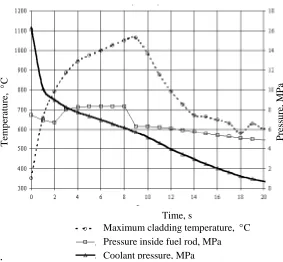
Initial stage of LB LOCA at WWER-1000 RP, also called as the first stage and characterized by quick variation of coolant parameters within the first 15÷20 s, is the least studied process of the accident scenario. Calculational evaluations show that this time interval could be the governing for further behaviour of fuel rod and, accordingly, for the accident scenario. In the accident occurring in case of guillotine break of the main coolant pipeline in WWER-1000 (LB LOCA), the coolant pressure in the core at the initial moment drops from 16 to 5 MPa, and within the following 7÷8 seconds it drops just to 0,5 MPa. Fuel temperature within this time period begins to decrease quickly, and temperature of fuel rod claddings, on the contrary, begins to increase abruptly, and within the first 7÷8 seconds they are equalized. Pressure of helium inside and of steam outside the fuel rod also become comparable, and at reaching the maximum temperature on cladding within the first 8÷10 s
the helium pressure will exceed the outside steam pressure by 2,0÷3,5 MPa (fig. 1). Due to high temperature and considerable exceeding the inside pressure above the outside pressure, the claddings of the most-powered group of fuel rods undergo ductile-plastic deformation, and just at this stage of the accident the local ballooning and
loss of integrity of the claddings could occur
.
For numerical description of the processes of ductile-plastic deformation of fuel rod cladding under quick changing of the loading conditions the experimental check is required with the accident scenarios corresponding to the design understanding the processes of the core accident scenarios [1]. Full reproducing the scenarios of the accident initial stage is rather difficult from the technical point of view, as, for example, implementation of high impulse load on fuel rod simulator heater, being of the order of 100 kW/m, as well as the necessity to synchronize the parameters and rates of their variation in the course of the experiment. The experiments, performed earlier in different organizations of Russia on studying the behaviour of fuel rod claddings at the accident initial stage, consider, as a rule, only its separate aspects due to difficulties in reproducing the whole combination of the effects on fuel rod cladding, and use the method of direct electric heating of claddings that could effect noticeably the mechanical properties of cladding materials during tests. Due to the listed difficulties in experimental simulation of the accident initial stage a plant shall be constructed for testing a single fuel rod simulator, and technical solutions of this plant shall be further used in constructing the plant on testing the 7-fuel rod assembly.
.
Tempe
rature,
°
C
Press
u
re
, MPa
Time, s
Maximum cladding temperature, °C Pressure inside fuel rod, MPa Coolant pressure, MPa
Fig. 1 Variation of the core parameters at the initial stage of the accident scenario.
Purpose of the present work is the calculational-experimental simulation of thermomechanical behaviour of single fuel rod simulators with different power under the conditions of the initial (or the first) stage of the accident scenario in WWER-1000 RP with simulation of the heat accumulated in fuel rod and indirect cladding heating.
2. METHODS OF STUDY
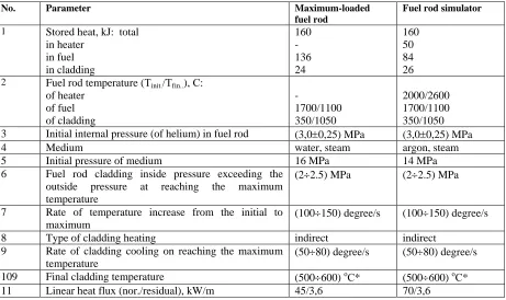
The authors have developed the calculational-experimental methods for studying the behaviour of single fuel rod simulators of WWER under the conditions simulating the initial stage of loss-of-coolant accident by maximum full combination of the parameters according to Table 1.
Table 1 Parameters of fuel rod simulation at the initial stage of the accident
No. Parameter Maximum-loaded
fuel rod
Fuel rod simulator
1 Stored heat, kJ: total in heater in fuel in cladding 160 - 136 24 160 50 84 26
2 Fuel rod temperature (Тinit./Тfin..), С:
of heater of fuel of cladding - 1700/1100 350/1050 2000/2600 1700/1100 350/1050 3 Initial internal pressure (of helium) in fuel rod (3,0±0,25) MPa (3,0±0,25) MPa 4 Medium water, steam argon, steam 5 Initial pressure of medium 16 MPa 14 MPa 6 Fuel rod cladding inside pressure exceeding the
outside pressure at reaching the maximum temperature
(2÷2.5) MPa (2÷2.5) MPa
7 Rate of temperature increase from the initial to maximum
(100÷150) degree/s (100÷150) degree/s
8 Type of cladding heating indirect indirect 9 Rate of cladding cooling on reaching the maximum
temperature
(50÷80) degree/s (50÷80) degree/s
109 Final cladding temperature (500÷600) оС* (500÷600) оС* 11 Linear heat flux (nor./residual), kW/m 45/3,6 70/3,6
3. METHODS OF TESTS
On the basis of the performed analyses the test conditions are determined for fuel rods on all parameters close to the parameters of the scenario presented in fig. 1, and a structure of the working section (RP) is developed for testing the fuel rod simulator [2].
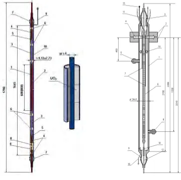
The test methods are tried-out at WWER fuel rod simulator (Fig. 2) in a set of the working section (RP) suitable for testing at high pressure (up to 20,0 MPa) (see fig. 3).
The heat accumulated in fuel rod is simulated with quick heating-up the fuel rod heater using electric current to the temperature of 1700-2000оС within 2÷3 s, after that the uranium dioxide pellets are heated within ∼ 5 s, followed by heating-up the fuel rod cladding – within 7-9 s. Then power on the heater is decreased to the
level simulating post-accident residual heat in fuel rods. Pressure variation outside the fuel rod cladding is simulated with opening the valve with the throttle of the preset diameter at the required moment.
Fig. 2 General view of fuel rod simulator
Fig. 3. General view of the working section
for testing a single fuel rod simulator
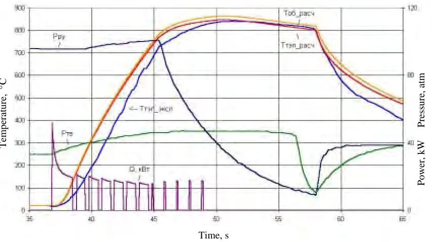
Results of comparison of calculations and experiments: for four startup Nos. 9, 10 for the cladding of alloy
Э110, and Nos.18, 19 for the cladding of alloy Э635, are presented in figs. 4÷7. Recalculation of fuel rod
cladding temperature is performed by the readings of TTT recording the cladding temperature at different places along its length.
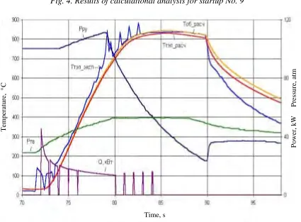
To integrate the results of calculation of temperature fields and pressures of design basis accident with calculations of the same parameters in the working section the main stage of test shall be started from the moment when the cladding temperature reaches 350 °С. It is seen from the given figures that by 8÷9th second after starting the main stage of test the fuel rod cladding temperature reaches its maximum. By that time the fuel rod cladding inside pressure becomes 1÷3 MPa more than the outside pressure due to quick pressure drop outside the cladding. This circumstance, in particular, is important for studying because at this stage of the experiment the cladding ballooning and loss of integrity could occur.
In figs. 4÷7 this stage is corresponded by the triangular region between curves (Рfr) and (РRP) within the
Power
,
kW
Press
u
re
, at
m
Tempe
rature,
°
C
Time, s
Fig. 4. Results of calculational analysis for startup No. 9
Power
,
kW
Press
u
re
, at
m
Tempe
rature,
°
C
Time, s
Power
,
kW
Press
u
re
, at
m
Tempe
rature,
°
C
Time, s
Fig.6. Results of calculational analysis for startup No 18.
Power
,
kW
Press
u
re
, at
m
Tempe
rature,
°
C
Time, s
Fig. 7 Results of calculational analysis for startup No 19.
the cladding by resistance welding using band of zirconium foil of thickness ~0,3 mm. With this, the great influence on temperature distribution is made by the complicated conditions of heat transfer. At the places of TTT junctions the heat transfer should be considered with presence of free convection with superimposing of the forced flow and radiation and contact heat transfer [3] under the conditions of some uncertainty in the value of a gap between the cladding and TTT junction.
The analysis performed for the behaviour of thermocouples with insulated junction, placed on fuel rod claddings by using resistance welding with the help of a foil, showed that for rapid processes with duration of about 10 s the temperature of TTT working junctions will be far behind the cladding temperature at the place of junctions by 200÷300 оС. Therefore in the given experiments the TTT were used with non-insulated, i.e. open junction. As it is shown by the performed experiments, the error in cladding temperature determination using such TTT did not exceed 50÷70 оС.
This should be supplemented with the fact that due to high electric current parameters during connection of power, reaching the values of 100÷120 kW/m, the readings of practically all TTTs with non-insulated working junction have noticeable interferences (figs. 4,5). Therefore for determination of cladding temperatures the TTT readings should be considered from the moment of power disconnection at the stage of slow temperature rise on the cladding owing to the heat accumulated on the heater and pellets. At this stage of experiments the readings of TTT with non-insulated junction, installed in one and the same places, did not practically differ from one another with discordance in readings of not more than 3%.
2. EXPERIMENTAL RESULTS
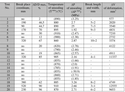
Some experimental results, and namely, the values of maximum deformation and change of internal volume due to cladding ballooning, are presented in Table 2. Analysis of the results of cladding deformation study showed that:
- experiments Nos.1, 9, 12 – 17 took place without cladding deformations;
- in experiments Nos.2, 3, 4 and 7 loss-of-integrity of fuel rod claddings occurred due to local circumferential deformation of 45÷70%;
- in experiments Nos.5, 6, 8 and 10 no loss-of-integrity of fuel rod claddings occurred though they have accumulated circumferential deformation of 10÷30%, extended over the cladding height. Complex character of its distribution is caused by the effect of fastening the housings and junctions of thermocouples on claddings;
- in experiments Nos.11, 18, 19 and 20 the maximum circumferential deformation of fuel rod claddings is 60÷90%. Extension of deformation over the cladding height is limited by thermocouple fastening, moreover, in the fastening zones the decrease in the cladding outer diameter is noticed in relation to the initial diameter by 2 - 3%.
A conclusion can be made that the character of fuel rod cladding deformation in the presented series of the tests differs significantly that is caused by difference in parameters variation in the course of the experiments. The cladding deformation behaviour in the course of the experiment is influenced by the following factors:
- rate of temperature rise and its maximum value;
Table 2 Parameters of cladding deformation and loss of integrity
Test No.
Break place coordinate,
mm
∆D/D max, %
Temperature of unsealing
(T max) (оС)
∆Р
of unsealing (∆Рmax) (MPa)
Break length and width,
mm
∆V of deformation,
mm3
1 no 2 (890) (3.25) - 577
2 190 46,5 880 2.7 5×2 2020
3 90 44,7 890 25 7×3 3540
4 170 70 895 1.92 9×3 4831
5 no 30 (910) (2.47) - 7210 6 no 12 (900) (2.38) - 2732
7 320 67 860 2.87 10×2 3374
8 no 20 (820) (2.78) - 4122
9 no - (790) (2.46) - -
10 no 19 (865) (2.57) - 4911
11 320 85 905 2.16 4×1 11337
12 no - (855) (1.66) - -
13 no - (870) (2.0) - -
14 no - (785) (1.91) - -
15 no - (855) (-50.9) - -
16 no - (860) (2.71) - -
17 no - (855) (1.85) - -
18 380 62 885 3.26 8×2 4749
19 520 90 910 2.66 3×1 12555
20 230 96 870 2.71 6×2 9653
Deformation behaviour of claddings depends, to a large extent, on the value of temperature at which equalizing of outside and inside pressure occurs, that is, cladding pressure differential (∆Р) becomes equal to zero. Position of the point where change of pressure differential sign occurs (Рfr ≈РRP) in 19 experiments varied within the cladding temperature range from 730 оС to 990 оС at pressure in fuel rods from 3,4 MPa to 5,8 MPa;
In the course of testing 20 single fuel rods the loss of integrity of 8 fuel rods was observed (5 - with claddings of alloy Э-110, 3 - with claddings of alloy Э-635), different extent of deformation was observed on 14 claddings (11 – of alloy Э-110, 3 – of alloy Э-635). Maximum cladding pressure differential after the point of sign change in different experiments was from 1,6 MPa to 3,3 MPa at cladding temperatures from 770 оС to 880 оС.
5. CONCLUSION
The methods have been developed for performing the tests of a single fuel rod simulator of WWER-1000 type reactor at the test bench PARAMETER under the conditions simulating the first stage of large-break loss-of-coolant accident (LB LOCA). The special working section and fuel rod simulators with indirect cladding heating have been designed and fabricated, as well as the process systems providing for implementation of methods for performing the experiments on simulation of the first stage of loss-of-coolant accident. The process of fuel rod cladding heating at the first accident stage was simulated till reaching the cladding maximum temperature with the fuel rod internal impulse heating to ∼1000 оС and duration of the impulse being ∼ 8÷11 s. Comparative calculations were carried out for the experiments simulating the initial stage of design basis accident during tests of single fuel rod simulators at the test bench PARAMETER, and it is demonstrated that under the mode of quick heating, the temperature-force parameters, corresponding to the scenario of the first stage of design basis accident at WWER-1000 RP, can be reproduced with high accuracy. On the basis of the specified calculational model, considering the variation in the values of contact stresses between fuel rod cladding and TTT working junction in the course of the cladding heating, the calculations of temperature fields have been carried out for fuel rod cladding and TTT, fixed on the cladding, under the conditions of the first stage of design basis accident with the heating rates of ~ 70 – 100 оС /s.
REFERENCES
1. Spasskov V.P., Shumsky A.M., Semishkin V.P. et al. Transactions of the International Conference “WWER Safety Thermal Physics Aspects”, 1998, v.2, pp.42-51.
2. Deniskin V.P., Konstantinov V.S., Nalivaev V.I. et al. Transactions of the 3rd Scientific-Technical Conference “Safety Assurance of NPP with WWER”, 2003, n.4, pp 223-230.