ABSTRACT
Dharap, Ashutosh Sachin. Construction and Initial Testing of Spark-Ignition Optical Engine (Under the direction of Dr. Tiegang Fang).
A spark ignition Bowditch type optical engine was constructed for this project using a
Ford 4.6L engine. Optical engines are important research tools as they remain the only practical means of visually studying flame propagation in internal combustion engines. Optical access engines allow us to study flame speeds, combustion regimes and temperature
distribution inside the combustion chamber. All these factors are critical for engine performance, combustion chemistry and emissions and studying them can lead to a better
understanding of the combustion process in IC engines as well as ways to improve engine performance and efficiency. Another important line of investigation possible with optical access engines is the study of engine knock. There are many theories of engine knock and
these can be visually verified and their mechanism studied with an optical access engine. The optical access system provides researchers the basic apparatus to study these
phenomena. For this project, the optical access insert was designed and fabricated with a concave surface for full bore imaging. Allied systems for driving the optical engine, heating, lubrication, fuel delivery, ignition and electronic systems for control and data collection were
Construction and Initial Testing of Spark-Ignition Optical Engine
by
Ashutosh Sachin Dharap
A thesis submitted to the Graduate Faculty of North Carolina State University
in partial fulfillment of the requirements for the degree of
Master of Science
Mechanical Engineering
Raleigh, North Carolina 2017
APPROVED BY:
_______________________________ _______________________________
DEDICATION
BIOGRAPHY
The author was born in Mumbai, India in 1993. An early fascination with automobiles
and IC engines caused him to study Mechanical Engineering at Mumbai University. The coursework and external competitions during this period got him especially interested in thermal engineering as a profession. To this end he decided to pursue a Master of Science
ACKNOWLEDGMENTS
I would like to acknowledge my advisor Dr. Tiegang Fang, for the opportunity to
work on this project and for the invaluable and varied theoretical knowledge and practical skills I learned under his guidance. Next I would like to thank my committee members, Dr. Stephen Terry and Dr. Alexei Saveliev for their patience and support as well as for teaching
two of my graduate courses. Their high quality of instruction and engaging style of teaching significantly improved my understanding of the science behind my chosen field of study.
I would like to give a special thanks to Andrew Martin and Ahmed Alhussain for their help in putting together the engine. I would also like to thank my fellow researchers Libing Wang, Heramb Karnataki, Himanshu Londhe, Reuven Gomes, Fujun Wang and Zengyang
Wu for their valuable inputs and help during the project.
I would also like to thank Neil Bain, Gary Lofton and Steve Cameron for the parts
TABLE OF CONTENTS
LIST OF TABLES……….vi
LIST OF FIGURES………..vii
1. INTRODUCTION……….1
1.1 Recent Research………1
1.2 Previous Work on Engine Used in this Project………. 8
2. DESIGN OF OPTICAL WINDOW FOR ENGINE………...13
3. FABRICATION OF OPTICAL COMPONENTS………..25
4. DRIVING MOTOR………...30
4.1 Motor Specifications………..…...……….………...…….30
4.2 Engine Starting Torque……….……….31
4.3 Motor Frame………..………...34
4.4 Motor Mount………..………....36
4.5 Variable Frequency Drive……….……….40
5. ENGINE SYSTEMS……….…..………...43
5.1 Lubrication System………...43
5.2 Coolant System……….44
5.3 Exhaust System……….47
5.4 Fuel System………...48
6. ELECTRONIC COMPONENTS and CONTROL BOX………...50
6.1 Injector Driver Circuit………..………..51
6.2 Ignition Circuit……….………..52
6.3 Engine Position Signals………..………53
6.4 Pressure Sensor……….………..54
6.5 Control Box Schematic………...57
7. AIR-FUEL RATIO………..59
7.1 Fuel Metering………..59
7.2 Airflow Metering………...…….….60
7.3 MAF Sensor Calibration……….61
7.4 LabView Program For Combustion………62
8. COMBUSTION TEST……...……….63
9. CONCLUDING REMARKS………..64
10. REFERENCES………..68
APPENDIX - A. LABVIEW PROGRAM……….71
LIST OF TABLES vi
Table 1 – Original Engine Specifications………...………...………….8
Table 2 – Driving Motor Specifications…………...……….30
Table 3 – Engine Specifications for calculating starting torque………32
Table 4 – Motor Frame Dimensions………..………...….34
Table 5 – Raw materials used for motor mount………36
Table 6 – Mitsubishi FR-D720-318-NA………...41
Table 7 – Water Pump Specifications………...44
Table 8 – Heater Specifications………45
Table 9 – Fuel Pump Specifications……….49
Table 10 – Ignition Coil Details……….52
Table 11 – Ignition Coil Driver………..52
Table 12 – Pressure Sensor Properties………...54
LIST OF FIGURES vii
Figure 1 - PM10 Concentrations Across Newcastle……….1
Figure 2 - Readout Of Combined Air Pollution Levels………2
Figure 3 - Bowditch-Type Optical Access Engine……….………..3
Figure 4 – Contours Of Equivalence Ratio Of Mixture………...….5
Figure 5 - Experimental Setup For Plasma Assisted Ignition In GDI Engine……….6
Figure 6 – Flame Development With Stock Plug vs Plasma Assisted Ignition………7
Figure 7 – Original Assembly………...9
Figure 8 – Extended Piston Dimensions……….10
Figure 9 - Extended Piston………...13
Figure 10 - Exploded View Of Model……….………14
Figure 11 – Original Plexiglas Window.………..17
Figure 12 – Window Cross-Section.………18
Figure 13 – Cup Cross-Section………....18
Figure 14 - Window Cad Model………..19
Figure 15 - Assembly Cad Model.………...19
Figure 16 – Ramped Load………....20
Figure 17 - Assembly Mesh……….…20
Figure 18 – Rigid Supports……….….21
Figure 19 - Von Mises Stresses On Piston Top………....22
Figure 22 – Deformation Of Piston Top……….24
Figure 23 – Deformation Of Piston Bottom………...24
Figure 24 – Steel Cup To Hold Window………25
Figure 25 – Threaded Retainer Ring, Bottom………....26
Figure 26 – Custom Wrench End………...26
Figure 27 – Window Bottom………..27
Figure 28 – Window Top………27
Figure 29 – Re-Machined Window………28
Figure 30 – Slight Wear On Extended Piston Top Surface………... 29
Figure 31 – Threads For Retainer Ring……….29
Figure 32 – Pressure Test Kit Readout and Location………32
Figure 33 – Dimension Reference……….34
Figure 34 – Driver Motor……….……….35
Figure 35 - SolidWorks Model For Motor Mount……….37
Figure 36 – Mesh For Motor Mount………..37
Figure 37 – Motor Mount Deformation……….38
Figure 38 – Motor Mount Von-Mises Stresses………..38
Figure 39 – Motor Mount and Damping Blocks………...39
Figure 40 – Variable Frequency Drive………..42
Figure 41 – Oil Drip For Extended Piston………43
Figure 42 – Coolant System………..45
Figure 44 – Water Pump………46
Figure 45 – Exhaust Piping………...47
Figure 46 – Fuel Tank and Fuel Pump………..48
Figure 47 – Fuel Pressure Regulator……….49
Figure 48 - Control Box………50
Figure 49 – Optical Switch To Detect Camshaft Position………...53
Figure 50 – Pressure Sensor, 603b1………..54
Figure 51 – Pressure Sensor Hole and Dial Gauge For Measuring Valve Lift……….55
Figure 52 – Charge Amplifier………...56
Figure 53 – Control Box Schematic………..57
Figure 54 – BNC Ports………..58
Figure 55 – Serial Port and Mil-Spec 4 Pin Connector……….58
Figure 56 – MAF Sensor and Ball Valve………...60
Figure 57 – Images from Representative Combustion Video………...63
Figure 58 – Optical-Access Engine, Driving Motor and Coolant System Visible………...66
CHAPTER 1 - Introduction 1.1 Recent Research
Spark ignition engines are currently the most commonly used engines in light duty motor vehicles. These constitute the bulk of road going vehicles in densely populated, traffic-prone areas. It’s in these areas that vehicle emissions are likely to have the most impact on
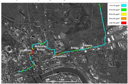
human health. A good illustration of this is the study described in reference [1]. In this studies portable air quality monitors were carried around in backpacks in Newcastle to
measure the local variation of air pollutants. The results were then visualized as a contour plot on a map. One of these plots is given in figure 1.
This figure shows the variation of particulates over moderate distances. As is evident from this illustration, local pollution levels increase significantly around slow, idling vehicles.
Figure 2 - 2014 US Green House Gas Emissions[2].
Air pollution is responsible for a very large number of ailments including asthma,
bronchitis, lung cancer, etc[3][4][5]. Since the bulk of vehicular pollution released in the immediate vicinity of populated areas comes from SI engines[15], more research is needed in this area. This need stems from both an ethical responsibility towards public health as well as
regulatory pressures with ever-stricter emission control laws. It is however worth noting that the increase in PM and HC emissions are partly a result of strict CO2 emissions limits[6].
The overall increase in petroleum prices over the last few decades has also created an incentive for ever more fuel-efficient engines. Two other important areas of research are controlling engine knock and controlling production of engine deposits. All these objectives
optical-Some of the important developments in optical-access engine research are described here. The type of optical engine used here is a Bowditch-type optical engine. This is a simple
and very effective method of providing optical access. It was first described by Fred Bowditch of General Motors in 1961[7].
Figure 3 - Bowditch-type optical access engine[7].
There are a number of reasons this engine is better suited for engine research than
competing configurations like transparent cylinder heads or optical access windows on the sides of the combustion chamber.
The biggest advantage of this type of engine is the fact that it involves minimal modifications to the combustion chamber and no modifications to the engine head beyond a longer timing chain/belt. The engine block, engine head, valve timing, water jacket and
experimental results obtained from a setup like this are very close to on-road operating conditions for similar engines.
Contrast this with an optical access engine that has a quartz engine block or worse, engine head. In this case, the heat transfer rate, engine temperature, valve timing and other operational parameters are significantly altered relative to stock engine.
Another advantage of the Bowditch-type engine is it’s robustness. Since everything except the optical window is either stock or made of steel/aluminium, the only vulnerable
part of the setup is the window. In case it breaks for any reason, it can be removed and replaced very easily and quickly. This makes maintenance and repairs very easy.
A third advantage of this configuration is the ease of cleaning the window. During
combustion deposits are formed on the top surface of the window and oil splashes on it from the bottom. Since the window can be removed and reassembled in under a minute, it’s
possible to clean the window before every run so as to get very clear images with a high speed camera.
A good example of non-combustion research with optical engines is a project on
mixture formation using visible & UV lasers[8]. In this project, an optical access engine was used to study mixture formation in a direct-injection IC engine. For this project visible & UV
lasers were used to determine the equivalence ratio at various points inside a combustion chamber. Since there was no combustion involved and direct injection was used, the results and analysis are valid for both compression-ignition and gasoline direct-injection engines.
the paper is shown below. Figure 4 shows the concentration of fuel and equivalence ratio at various points.
Figure 4 – Contours of equivalence ratio of mixture[8].
Research similar to this was instrumental in the development of techniques like stratified
charge engines for improving fuel economy and reducing emissions.
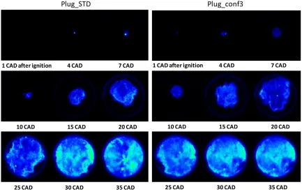
A much more recent example of research using a Bowditch-type optical access engine
is a project from 2013 at Istituto Motori di Napoli – CNR[9]. In this project a Gasoline-Direct-Injection optical engine was constructed and used for investigating the impact of Plasma Assisted Ignition on flame stability and combustion limits. An illustration of the
Figure 5 - Experimental setup for Plasma Assisted Ignition in GDI engine[9].
This project involved a detailed analysis of flame propagation for stock system with regular ignition as baseline and for Plasma Assisted Ignition to quantify the benefits of the
latter. Flame speed, flame propagation mode, IMEP and pressure curves were obtained for all cases. There were two main outcomes from this project that are interesting for researchers.
More importantly it was determined that PAI increased lean burn limits and reduced partial burn. This is extremely critical and positive news for GDI engine development. While
GDI engines are more efficient than port injection engines, they have a severe problem of soot formation and oil droplets from crankcase ventilation being baked onto valves. If the lean burn limits can be stretched and partial burn reduced, it would significantly improve the
soot emissions from GDI engines. It would also increase engine efficiency and reduce the chances of engine damage caused by engine deposits breaking off in small droplet sized
particles and entering turbochargers.
This analysis throws up some interesting questions such as how far the lean burn limits can be pushed with different configurations for injector placement or by using PAI
with multiple spark plugs. A representative image from the paper is shown in figure 6.
1.2 Previous Work on Engine Used in this Project
The specific engine used in this project was constructed at Rutgers in 1996 by Fadi Tarazi[10]. The original engine was a Ford 4.6L V8 from a Mustang Cobra. Two engines of this type were used to make the optical access engine. One engine provided the base engine
block for the engine. The second engine provided the extended engine block that forms the combustion chamber for extended piston. The original specifications for this engine are given
in table 1.
Table 1 - Original Engine Specifications[11].
Engine Model Ford 281in 3 (4.6L) V8 DOHC
Ignition Type Distributor-less non-wasted spark Fuel Delivery Method Multi-port fuel injection (MPFI) Number of Strokes per Cycle 4
Bore 3.551in (90.2mm)
Stroke 3.543in (90mm)
Connecting Rod Length 5.96in (151.5mm)
Compression Ratio 9.9 : 1
Clearance Volume 3.051in 3 (50cm 3 ) Number of Valves per Cylinder 4
Intake Valve Lift Intake Valve Diameter
0.259in (6.59mm) 1.752in (44.5mm) Exhaust Valve Lift
This engine was modified into a Bowditch-type optical access engine. The detailed report of this modification can be found in reference [10]. The pertinent details are briefly
summarized here. The engine head was removed from the right cylinder bank of one engine to make space for the extension. The top half of the engine block on one side of the V was sawed off from the second engine. This acts as the combustion chamber for extended piston.
This extension was installed 7 inches above the top of the first engine. Eight steel tubes passing over the head bolts were used to space out the extension from the original block.
The extended piston was machined from a single steel cylinder. This had internal threads on top to hold the window and was bolted into the original piston at the bottom. A window and threaded retaining ring were designed for the extended piston. The extended
piston couldn’t use the stock splash oiling system, so it was fitted with graphite piston rings to get around this problem. It also had a silicon window that was transparent to infrared light.
This allowed for investigations into the temperature distribution inside combustion chamber.
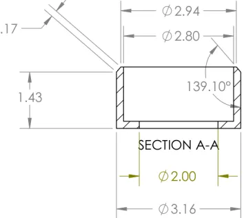
The dimensions of extended piston are given in figure 8.
This engine was later modified slightly during another project in 2008[11]. The graphite rings were replaced with OEM steel rings. A drip hole was drilled radially into the
engine block to drip motor oil onto the extended piston just below the top ring. This eliminated the wear problems of the graphite rings. A new extended piston was made to the same dimensions as the old one suffered some damage. A pressure sensor tap was made in
the side of the engine head through a rib in the water jacket.
This project involved multi-spectral infrared imaging of combustion. The primary goal was to verify the Time Derived Spatial Averaging (TDSA) method for predicting fuel octane number. TDSA is an image processing algorithm that compares relative flame
propagation speeds between various fuels. Thus based on a baseline fuel’s results, it can estimate the additives present in other fuels relative to base fuel. In this study, 10 fuels were
tested. Two were base fuels and eight were base fuels with additives. The study was blind and tester only knew random numbers for each fuel. The study confirmed that TDSA can predict the presence of additives with reasonable accuracy. However while this method can correctly
identify the presence of octane improvers, it cannot differentiate between cetane improvers and combustion enhancers since both have similar effects on combustion characteristics.
This has been a brief review of a few representative research efforts involving Bowditch-type optical access engines. All these projects have investigated different aspects
the efficacy of lubricating oils and coolants at various temperatures[12], the effects of knock[13], validation of computational fluid dynamics results with optical engines, etc.
As evident from this brief review of a few recent research efforts, there are many possible avenues of research with an optical-access engine. Another observation common to
many of these projects is the extreme cycle-to-cycle variation of combustion. This complicates efforts to gather statistical data. It also makes validation of CFD code very
Chapter 2 – Design of Optical Window for Engine
The engine is a Bowditch-type optical-access engine. The most critical part to be designed
was the optical window and retaining ring. The figures 9 and 10 show an exploded view of the extended piston and the optical window and retaining ring fitting inside it.
For this project, the end objective is to conduct research with a high-speed camera operating in the visible spectrum. Therefore we could not use the silicon window. A new
window and retaining ring was designed. Conventionally the window on optical engines is made of either fused quartz or sapphire glass. These however have some significant problems.
Both materials are quite heavy. This put undue tensile load on the RTV layer holding
window when the engine crosses TDC, owing to inertial loads. This requires a large surface area on which the RTV can act. This in turn reduces the visible optical area on the bottom of optical window. This is highly undesirable as much smaller sections of the engine bore are
visible.
The second issue with quartz and sapphire glass is it’s inability to withstand continuous combustion. These materials fail if there is combustion for more than 8-10 consecutive cycles. This reduces the accuracy of experimental results. One of the most
significant drawbacks of optical-access engines is their inability to sustain combustion long enough to heat up to the temperatures at which engines operate in real life conditions. We can
mitigate this problem to an extent by using an immersion heater to heat coolant water and circulate it through the water jacket. This provides an acceptable approximation of engine block temperature. However there’s no way to heat up the valves, and engine head. The only
The last issue with quartz and sapphire glass is it’s cost and machinability. Both materials are very expensive. They are also very hard and brittle. Therefore machining them
is very difficult. Specialized tools and processes are needed to fabricate and polish these materials. In case it is accidentally overloaded and breaks, replacement would be a very difficult and time-consuming job.
To get around these problems, we were looking at alternative materials for the
window. Briefly the material had to survive combustion temperature and pressure, provide good optical clarity and be easy to machine and polish.
We finally decided on Plexiglas for the optical window. It is rated for the pressures and temperatures reached in engines. It has very good optical clarity. It is relatively very
cheap and easy to obtain. It is also less brittle and thus easier to machine. It can be turned on a lathe to the required dimensions and polished.
There has been at least one project where a Plexiglas window was used in a Bowditch-type optical access engine. This was used in a research project at University of
Oxford, UK in 2007[14]. In this project, a single cylinder DISI spray guided engine was used with modifications for optical access. A 60mm Plexiglas window was used in this case. It was tested to breaking point to see how much it could take. As per their results, it could
This is a very significant improvement over both sapphire glass and fused quartz. Therefore we decided that Plexiglas would be a practical material for the optical window.
The window was machined from a Plexiglas cylinder, diameter 4” and length 5”.
Apart from a new material, the window was also given a concave shape at the bottom
edge so it acts as a converging lens. This provides a view of nearly the entire combustion chamber, including a part of the squish region at the edge. The window was initially
machined to have a very small radius of curvature but this caused problems with distortion correction. To correct this issue, the window was later re-machined to a larger radius of curvature.
Pressure data from a heavy-duty optical CI engine from the same lab was used to decide the expected operating load on the engine. This is a Cummins SCE-903 marine engine
with 1.8L cylinders. This test bed records pressures in the vicinity of 7.5MPa when knock is observed. To ensure the window would not fail, twice this pressure, 15 MPa was assumed to be acting on the window for the purposes of design calculations.
The window was modeled in SolidWorks along with the cup and retainer ring. The cross-sections of the window and cup are in figures 12 and 13.
Figure 14 - Window CAD model
A static Finite Element Analysis was performed on the assembly using ANSYS 16.0. A ramped load of 15 MPa was assumed to be acting on the window. The following load was
applied on the assembly -
Figure 16 – Ramped load
Figure 18 – Rigid Supports
The side of the outer cup fits tightly against the steel extended piston. The bottom is supported by a steel retainer ring torqued into position. Therefore both these side can be assumed to have negligible deflection and are therefore defined as rigid supports in the
Figure 19 - Von Mises Stresses on Piston Top
Figure 21 - Region of maximum stress
As we can see here, the stress concentration is on the copper ring and steel cup which
Figure 22 – Deformation of Piston Top
Chapter 3 Fabrication of Optical Components
-The optical window, window cup, retainer ring and copper rings were fabricated in
the Biological and Agricultural Engineering machine shop at NC State. The cup to hold the window was fabricated from a stainless steel cylinder.
Figure 24 – Steel Cup to hold Window
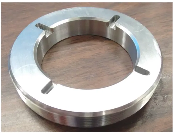
The threaded retaining ring was made from the same stainless steel cylinder. There
were some issues with fabricating the retainer ring. There were no details about the thread dimensions for extended piston. Thus it proved necessary to extract the extended piston and take it to the machine shop so that the threads could be matched directly. This also
Figure 25 – Threaded Retainer Ring, Bottom
A custom wrench end was required to turn the retainer ring and torque it into position. This wrench end was also made from the same stainless steel cylinder. This wrench end fits
into the slots on the bottom of retainer ring. The square hole in the center is sized to fit a standard 1/2” socket wrench. The optical window was fabricated from a Plexiglas cylinder with diameter 4” and length 5”.
Figure 27 – Window Bottom
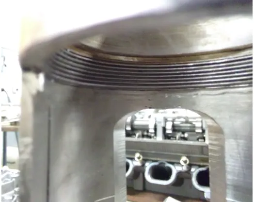
This curvature radius allowed imaging of almost the entire combustion chamber including part of the sides of combustion chamber at TDC. However the radius of curvature
was too small and it was found that distortion correction would be too difficult. So the window was re-machined to increase the radius of curvature. This sacrificed viewing angle for easy distortion correction.
By the time this was decided, the window had already been glued into the cup with RTV60. Rather than risk damaging the window while removing it, it was machined while
glued inside. The re-machined window is shown in figure 29.
Figure 29 – Re-machined window
Figure 30 – Slight wear on extended piston top surface but otherwise undamaged
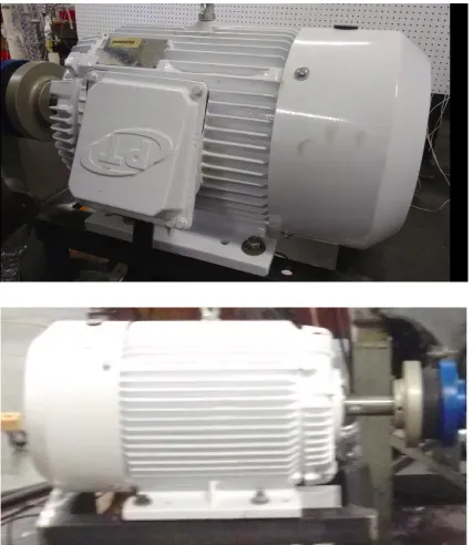
Chapter 4 - Driving Motor 4.1 Driving Motor Specifications
Optical engines cannot run under their own power owing to their inability to sustain combustion for more than a few cycles. Therefore an external driver is required to keep these engines running at a specific speed. In this case an electric AC motor has been used to drive
the engine. The motor specifications are listed in table 2. This is a NEMA Type D, high-slip, TEFC oil-well motor. Large locked rotor starting torque was the reason for selecting this
specific motor.
Table 2 – Driving Motor Specifications
Model Number OP1060
HP 10
Pole 6
Synchronous RPM 1200
Full Load RPM 1130
Frame 256T
Full Load Torque (FLT), ft-lbs 46.27
Max Torque / FLT 295%
Locked Torque / FLT 285%
Locked Current at 460V 78A
Bearing Size 6309
Gross Weight, lbs 293
Efficiency 85.5%
Power Factor 77%
4.2 Engine Starting Torque
To determine the locked rotor torque required from the motor, a simple analysis of
starting torque based on compression load was carried out. In this specific engine, only cylinder 1 has a piston present, and therefore is the only cylinder with compression. The remaining pistons have been removed to reduce friction losses. The original flex plate was
replaced with a very heavy flywheel[10]. Apart from this weights were added to the crankshaft for balancing[11].
In both cases, no further details have been provided about these modifications. It was also deemed unnecessary and impractical to take the engine apart and measure the weights of individual components. Therefore no analysis of inertial and friction load was practical for
determining required starting torque. A very conservative approach was adopted to calculate starting torque required from the motor. Peak motoring pressure was assumed to be acting on
the cylinder throughout the compression stroke. Instantaneous torque was calculated halfway through the compression stroke. The logic being that if the motor were to cut out during the compression stroke, piston pressure would force the engine back to bottom dead center.
Therefore, in the worst case scenario, the engine would still start close to bottom dead center in the compression stroke and the maximum compression load would be less than what was
calculated. To account for indeterminate inertial and friction loads, the sum total of these loads was assumed to be equal to half the compression load.
The relevant dimensions and details required for this calculation are listed below.
Table 3 - Engine Specifications for calculating starting torque Peak Compression Pressure 110-120 PSI / 0.758-0.827 MPa
Crank Length 0.75” / 19mm
Piston Diameter 3.55”
Calculations for starting torque are briefly summarized below. All calculations are in US customary / imperial units rather than SI units since both engine specifications and motor
specifications are in these units.
Piston Area = 0.25 x π x diameter2 = 0.25 x π x 3.552 = 9.89 in2 Peak Compression Pressure = 115 PSI
Force acting on piston surface = Piston Area x Peak Compression Pressure = 1137.69 lbf Crank Length = 0.75” = 0.0625 feet
Compression Torque = Force x Crank Length = 1137.69 x 0.0625 = 71.1 lb-ft
As a conservative estimate the total starting torque was assumed to be 1.5 times the starting torque. This gives a starting torque of 106.65 lb-ft. This is an estimate that grossly
overestimates the required starting torque. Therefore any driving motor that provides comparable locked rotor torque is adequate to drive the engine.
Motor Starting Torque
-Full Load Torque (FLT) = 46.27 ft-lbs Locked rotor torque / FLT = 285%
Locked rotor torque = FLT x 285% = 46.27 x 2.85 = 131.87 ft-lbs Motor Starting Torque = 131.87 ft-lbs
This torque is higher than calculated engine starting torque. Since the calculation is an overestimate of required torque, this motor is adequate to drive the engine. Subsequent testing has confirmed the motor’s ability to drive the engine under compression and to easily
4.3 Motor Frame
This specific motor uses a standard NEMA 256T frame. The dimensions are give below
-All dimensions are in inches:
Table 4 – Motor Frame Dimensions Frame
Size D E 2F H dia 4 holes Udia BA Vmin Key
256T 6-1/4 5 10 17 / 32 1-5/8 4-1/4 3-3/4 3/8 x 3/8 x 2-7/8
Figure 33 – Dimension Reference :
The only variable size is shaft size which is decided by the manufacturer. In this case, the shaft size is exactly equal to the minimum shaft size specified for this frame by NEMA. The
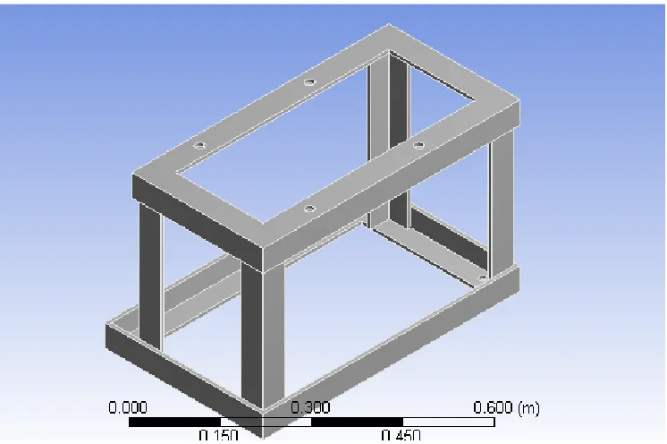
4.4 Motor Mount
A motor mount was made from 304 steel angles to hold the motor in the correct
position. There were four design requirements for this mount
-• It should be able to support the motor at the correct position to connect with right angle coupling.
• It must be able to take the static and dynamic loads exerted by the motor.
• There should be a small clearance between the motor and the top surface of mount for damping pads.
• The bottom of the stand should have holes that align with threaded holes already present in the steel bed on which which engine is supported.
A CAD model was made in SolidWorks and a static FEA analysis was carried out in ANSYS to confirm that it could take the applied loads with minimal deflection.
Table 5 Raw materials used for motor mount
-Type Material Cross-Section
Dimensions (Inch)
Angle Mild Steel 5/16 x 5/16 x 2
Mounting pads Green Neoprene Rubber, 500 psi
Figure 35 SolidWorks model for motor mount
Figure 37 – Motor Mount Deformation
Figure 38 – Motor Mount Von-Mises Stresses
The motor mount was made by welding together 5/16 x 5/16 x 2” steel angles. This was done in the MAE machine shop. Holes drilled on the mount were positioned to coincide
with holes on the motor and those on the test bed base. The holes in the base are 1/2–14 threaded holes. Corresponding bolts were used to fix the mount to base. For the top surface, 1/2–20 bolts and corresponding nuts were used to fix the motor to mount. The mount height
was intentionally selected to leave a little clearance between the mount and motor. This allowed fairly thick blocks of mounting pads to be inserted between the motor and it’s mount.
These blocks were ground to correct all misalignments. This ensured the shaft would be almost perfectly concentric with it’s corresponding number on the bevel gears.
4.5 Variable Frequency Drive
AC motors require a variable frequency drive (VFD) for controlled operation. Without a VFD, motors simply run at full power and maximum speed when plugged in. This is undesirable as it puts undue strain on the motor as well as engine components. It’s also
necessary to be able to control motor speed so that experimental results can be obtained from the engine at multiple speeds. This allows for investigation into the effect of engine speed on
flame development and other combustion phenomenon.
Apart from research objectives, there are practical concerns that necessitate a VFD.
The first is surge current. If an AC motor starts with a large load attached, it draws a very high initial surge current before it starts moving. This is called locked rotor current and can
be many times the full load current. A motor plugged into the wall will draw this current directly from the power outlet. This would require installation of an unnecessarily large capacity power outlet. A VFD can provide this current surge itself and therefore the wall
outlet only has to be capable of handling full load current.
VFDs also allow for a ‘soft start’ to minimize jerks and damage to the motor or driven load. In essence the VFD slowly ramps up motor current and controls the rate at which the motor accelerates to full speed. Similarly they also provide smooth deceleration instead of
For this engine a Mitsubishi FR-D700 series VFD was selected. This VFD was selected primarily because of it’s robustness and ease of use. Specifications for this VFD are
given in table 6.
Table 6 – Mitsubishi FR-D720-318-NA
Capacity 7.5 kW (10 HP)
Rated capacity (kVA) 12.7
Rated Current (A) 31.8
Overload Current 150% 60s, 200% 0.5s
Inverse Time Characteristics
Voltage 200 – 240 V, 3 Phase
Input Voltage and Frequency 200-240 V, 50/60 Hz Permissible Fluctuation 170-264 V, 50/60 Hz Permissible Frequency Fluctuation 5%
Supply Capacity (kVA) 17.0
Protective structure (JEM1030) Enclosed type (IP20)
Cooling system Forced air cooling
Approximate Weight 3.6 kg
The VFD is wired to the motor and wall outlet with AWG #6 wires. This wire gauge
has low resistance wires with large cross-section capable of carrying the 31.8A full load current without overheating. They also have shielding to minimize electrical interference
Chapter 5 – Engine Systems 5.1 Lubrication System
This engine largely uses the stock oiling system for most of it’s components. The stock oiling system uses a gerotor pump attached to engine crankshaft. It siphons motor oil from the oil pan and supplies it through passages cast in the engine block and head to the
camshaft, timing chain and bearings. The pistons are lubricated by splash lubrication. In this engine the oil passages between the top and bottom spaced out blocks were connected by
steel tubes for supply lines and heavy duty nylon tubing for return lines. This ingenious idea in the original modification ensures that everything except the extended piston uses the stock oiling system. This makes the system very reliable, easy to use and easily repairable.
For the extended piston there is a small hole in the cylinder liner just below the top piston ring. A 1/8” tube leads from this hole. A ferrule and pipe nut were clamped on the end
of this tube. Oil is supplied from an oil cup through a ball valve to regulate flow. The oil drips onto piston rings lubricating them.
5.2 Coolant System
Optical access engines have one significant drawback. They cannot reach the
temperatures usually reached in a regular engine. This is due to the fact that they have combustion for a very short amount of time. This affects the heat release, performance, emissions, heat transfer, etc. It is possible to mitigate this problem to an extent by heating the
engine block externally. Therefore the coolant water system in an optical access engine is, ironically, used to heat the engine. The stock water jacket is used. However the stock water
pump cannot be used due to the need for heating.
A 5 gallon cube shaped tank is used for storing the coolant. Three NPT couplings are
welded to the tank. A 1000W immersion heater is connected to one of the coupling. The other two couplings are used for inlet and outlet. A 1/2HP water pump is used to circulate coolant
water in the system. A 3/4” steel mesh filter is attached to tank outlet. This traps any debris in the coolant water and protects the pump. High temperature nylon hoses are used in this system.
Table 7 – Water Pump Specifications
Model WEG Hypro ‘JM’ type
Power 1/2HP
Flow Rate 55 GPM
Voltage 110V
Table 8 – Heater Specifications
Power 1000 W
Max Temperature 250 F
Temperature Control Dial setting with thermostat cutoff
Voltage 110V
5.3 - Exhaust System
In spite of the low volume of exhaust gas produced, it is still necessary to have an
exhaust system to remove toxic gases. The stock exhaust manifold was used here as it’s the simplest way to connect to the exhaust ports on engine head without any leakages. The manifold outlet was then welded to a 3/4” flexible, air-tight steel conduit. This conduit
carries exhaust gases out of the lab.
5.4 Fuel System
The fuel system for this setup uses a two gallon gasoline tank, an inline fuel pump
and a pressure regulator, all connected to the stock fuel rail with stock injectors. The two gallon gasoline tank is fixed to a steel mount bolted into test bed base. This tank has a medium mesh fuel filter inside the cap, a tap at the outlet on it’s bottom and an open return at
the back. 1/4” fuel lines are used throughout the system except the terminal end of the return line which has a 1/8” line and 1/4” to 1/8” reducing coupling near the return port on tank.
Table 9 – Fuel Pump Specifications
Model Bosch 044
Free Flow 300 LPH
Flow at 72.5 psi 200 LPH
Voltage 12 V
Inlet M18 x 1.5
Outlet M12 x 1.5
Weight 1.03 kg
The pressure regulator is a simple diaphragm valve capable of maintaining line pressure upto 140 psi. It has a pressure gauge for easy adjustment and verification.
Chapter 6 - Electronic Components and Control Box Electronic components for this system are mainly for the following
-• Injector driver circuit
• Ignition circuit
• Crank Angle and Exhaust TDC circuit
• Pressure Sensor
• Interface with NI DAQmx card and LabView Programs
6.1 Injector Driver Circuit
The injector driver circuit is a standard circuit used with the Texas Instruments
LM1949N injector driver IC. This circuit was soldered onto a blank circuit board. Once ready, this circuit is easy to use. It has only four pins: power (12 VDC), ground, input pulse and injector coil negative. The basic operation is quite simple. The injector driver, LM1949N,
receives input pulse to open injector. At this point it operates the Bipolar Junction Transistor which has a function similar to a relay. This temporarily grounds the negative coil of injector
6.2 Ignition Circuit
This circuit consists of an ignition coil, spark plug wire, spark plug, spark plug driver
and battery. The spark plug driver (MSD PN 6032 ) is inside the control box on the bottom left in figure 38. This driver receives the input pulse from LabView program. On receiving this pulse, the ignition driver grounds the ignition coil (Accel 8140) for a very short amount
of time, usually around 2ms. This causes the primary winding in the ignition coil to charge. When the ground is removed, a very large voltage is induced in the secondary winding of
ignition coil. This voltage creates the required spark. For this specific coil, the output voltage is 40000V. This type of high voltage helps to ignite the mixture faster and under more unfavourable conditions.
Table 10 – Ignition Coil Details
Model num Accel 8140
Input voltage 12V
Weight 1.55 lb
Output voltage 40000V
Table 11 – Ignition Coil Driver
Model num MSD PN 6302
Pins 5
6.3 Engine Position Signals -Crank Angle :
The shaft encoder connected to flywheel sends a TTL pulse for every ½ degree of shaft rotation. These pulses can be counted from an arbitrary point, usually exhaust TDC, to determine the exact position of the piston in the cycle at any given moment. These pulses can
be read by the DAQmx counter directly. Therefore crank angle output of shaft encoder is directly wired to BNC connector block.
Exhaust TDC :
The shaft encoder sends a TTL pulse precisely at every TDC. A less accurate sensor is mounted on the camshaft which gives a 5V output at and around the exhaust TDC. A logical
IC is used to perform an AND operation on these two signals. The output of this operation is logical high precisely at every exhaust TDC. Usually the camshaft sensor is a hall effect
6.4 Pressure Sensor
A Kistler 603B1 pressure sensor has been used in this engine. The sensor has an
adapter with 5/16-24 threads machined on the outside. This sensor has a range of 0-200 bar. Technical details for this pressure sensor are given below
-Table 12 – Pressure Sensor Properties
Property Units Value
Range Bar 0-200
Overload Bar 350
Sensitivity pC/bar ~-5.0
Natural Frequency kHz ~400
Acceleration Sensitivity Bar/g <0.0001
Operating Temperature oC -196 to 200
Temperature Coefficient of Sensitivity
oC-1 < 2 x 10⁻⁴
Capacity pF 10
Weight gm 1.7
Connector, Teflon Insulator M4 x 0.35
Pressure Sensor Mounting Hole
The original pressure tap on the engine was too shallow and thus compression
pressure didn’t really reach the pressure sensor. To correct this, the engine head was removed and the pressure sensor hole was drilled all the way through. The thread taps were also extended further inwards with a 5/16-24 tap.
This allowed the pressure sensor to sit flush with the inside of combustion chamber. After this the head was reassembled and camshafts were degreed with a micrometer dial
gauge.
Charge Amplifier Settings A Kistler 5004 charge amplifier with 180 kHz filter has been used.
Figure 52 – Charge Amplifier Amplifier settings
-Capacity, C = 10 pF Charge, Q = 5 pC/bar Voltage = Q / C = 0.5 V/bar
Therefore, mechanical units per volt = 1/0.5 = 2 bar / V
Dial Settings -Range : 1-11
Mechanical units / V = 2
6.5 Control Box Schematic
The control box is responsible for fuel injection, spark timing and acquiring crank
angle and exhaust TDC pulses. A basic schematic is shown below. The details of injector driver circuit have already been discussed. Therefore these are not shown. Instead a placeholder with 4 pins is shown for injector driver circuit to improve readability of the
schematic. Also there are two power sources inside the control box. One is a power box from 120 VAC to 12 VDC, the other is a power regulator IC LM7805ABV which steps voltage
down from 12VDC to 5VDC. Both these have also been omitted as they are extraneous details as far as circuit logic is concerned.
Control Box Pin-Out
Figure 54 - BNC Ports
Chapter 7 – Air-Fuel Ratio 7.1 Fuel Metering
Fuel metering is achieved by pulse width modulation for the signal sent to control box by DAQmx. PWM is easily possible with LabView programs. Calculation of fuel mass metered out based on pulse width is described here.
This engine uses Ford XR3E-C5B injectors. These are re-badged Bosch injectors, with model number 0-280-155-865.
Table 13 – Fuel Injector Specifications
Model number XR3E-C5B / 0-280-155-865
Impedance 14.1 Ω
Fuel Flow Rate @ 43 psi 24 lb/hr i.e. 3.03e-3 gm/msec
Based on MAF sensor output and required air-fuel ratio, the pulse width for injection can be calculated. An example calculation for 50% load is given below.
Mass of air in one cycle = Cylinder volume x load x density = 0.3522 gm
7.2 Airflow Metering
Optical-access windows have much lower strength than steel pistons and therefore
cannot survive full load (wide open throttle) combustion. Therefore an air restrictor and airflow sensor are essential.
The air restrictor used here is a simple ball valve with 1/2” tube diameter. This valve
when closed partially has the same effect on engine air intake as a partially closed throttle. A mass airflow (MAF) sensor has been installed between inlet of intake manifold and
ball valve. This gives real time data about the amount of air flowing through it.
7.3 MAF Sensor Calibration
The MAF sensor provides a voltage output proportional to the mass of air flowing
through it. The MAF sensor used here is a Bosch 0280217123 sensor. The stock calibration curve was found to be faulty and the sensor had to be recalibrated. It was calibrated using a mechanical rotameter, compressed air and ball valve. The ball valve was slowly opened, by a
few degrees at a time. The flow rate was read on the rotameter and noted down. The corresponding voltage output from the MAF sensor was also noted. Based on this a new
calibration curve was created.
To measure the mass flow rate, the MAF sensor was wired to the DAQmx. This allowed a LabView program to read the voltage output at a sampling rate of 10 kHz and
record all the values in an excel file. A MATLAB script was written to interpolate the flow rate for each sample from the new sampling curve and then find the mean of all these values.
This mean is the average mass flow rate through the sensor.
This is an iterative process if we decide a certain load condition and then change ball valve aperture to get the required mass flow rate. This was carried out to set the engine at
7.4 LabView Program to Control Combustion
A LabView program was developed during the course of this project that would control combustion and acquire in-cylinder pressure data. This program was used to test combustion but due to some issues with the hardware, pressure data couldn’t be acquired.
Chapter 8 - Combustion Test
In the final stage, the engine was tested with combustion. This was done to verify the
correct functioning of all components and subsystems of the test bed. The engine was run at 300 RPM and 50% load for all the tests. A sightly rich mixture with an air-fuel ratio of 12:1 was used. Smooth combustion was obtained in these tests as is shown in the accompanying
photographs taken from the videos recorded by a high speed camera.
Combustion was tried for 15 consecutive cycles. The Plexiglas window did not suffer
any damage or surface scratches as a result of combustion temperature or pressure. This proved that all subsystems worked correctly and all mechanical parts had adequate structural strength for their intended purpose.
Chapter 9 - Concluding Remarks
The optical-access engine constructed over the course of this project will serve as a
useful experimental apparatus for researchers interested in optical analysis of combustion. All the basic systems needed for running the engine function and have been tested. The curved window with full-bore imaging should give more complete and accurate results than those
obtained with flat windows which have been used in the majority of optical engine research.
The optical window and all other non-standard parts and subsystems have been subjected to finite element analysis with extremely conservative assumptions as well as physical testing. The driving motor, coolant, lubrication, fuel system, ignition system and
data acquisition systems have been shown to work reliably under combustion. Thus repeatable and accurate results can be obtained with this system.
There are many possible lines of investigation with this apparatus. A few options are described here. These are investigations that may yield academically interesting as well as
practically useful results.
The cylinder head could be replaced with a gasoline direct-injection (GDI) head. It would be interesting to compare the two injection methods on the exact same engine. By comparing the results with similar engines designed from the beginning for GDI, it would
The effects of varying compression ratio on flame propagation can be studied. This engine’s head is dome shaped and forms a significant portion of the clearance volume.
Therefore the compression ratio can be drastically changed simply by changing the engine head.
Another possibility is using a Gas Chromatograph to perform chemical analysis of
engine deposits for various combustion parameters. This would be possible because of the ease with which the optical window can be removed. This could potentially lead to findings
Photographs of the optical-access engine.
REFERENCES
[1] Deary, M.E., Bainbridge, S.J., Kerr, A. et al. Air Qual Atmos Health (2016) 9: 923.
doi:10.1007/s11869-016-0394-3
[2] US Environmental Protection Agency.
[3] Anderson HR, Atkinson RW, Peacock JL, Marston L, Konstantinou K (2004)
Meta-analysis of time series studies and panel studies of particulate matter (PM) and ozone (O3).
Report of a WHO task group. World Health Organization, Copenhagen
[4] Raaschou-Nielsen O, Andersen ZJ, Beelen R, Samoli E, Stafoggia M, et al. Air pollution and lung cancer incidence in 17 European cohorts: prospective analyses from the European
Study of Cohorts for Air Pollution Effects (ESCAPE). Lancet Oncol 2013;14:813–22.
[5] Zhang P, Dong G, Sun B, Zhang L, Chen X, et al. Long-term exposure to ambient air pollution and mortality due to cardio-vascular disease and cerebrovascular disease in
Shenyang, China. PLoS One 2011;6:e20827
[6] Henry, C., Kroll, S., Premnath, V., Smith, I. et al., "Detailed Characterization of Criteria
Pollutant Emissions from D-EGR® Light Duty Vehicle," SAE Technical Paper 2016-01-1006, 2016, doi:10.4271/2016-01-1006.
[7] F. W. Bowditch, "A New Tool for Combustion Research a Quartz Piston Engine," SAE
Technical Papers, no. 610002, 1961.
[8] Suzuki, M., Nishida, K. and Hiroyasu, H. (1994), Imaging of Drop and Vapour Clouds in
[9] Simona Silvia Merola, Luca Marchitto, Cinzia Tornatore, Gerardo Valentino, Adrian Irimescu, Optical characterization of combustion processes in a DISI engine equipped with
plasma-assisted ignition system, Applied Thermal Engineering, Volume 69, Issues 1–2, August 2014, Pages 177-187, ISSN 1359-4311
[10] Tarazi, F. I. Development and fabrication of an optical access ford 4.6l v8 engine
for internal combustion engine research. Master’s thesis, Rutgers University, 1996.
[11] VanderVeer, J. R., and Rutgers University. Graduate School--New Brunswick. (2008). A
study of in-cylinder combustion processes by using high speed multi-spectral infrared imaging and a robust statistical analysis method.
[12] P. I. Lacey, E. I. Frame and D. M. Yost, Bench Wear and Single Cylinder Engine
Evaluations of High Temperature Lubricants for U.S. Army Ground Vehicles, San Antonio: United States Army, 1994
[13] S. S. Merola , P. Sementa and C. Tornatore, Experiments on knocking and abnormal combustion through optical diagnostics in a boosted spark ignition port fuel injection engine, International Journal of Automotive Technology , Vol. 12, No. 1, pp. 93 −1 01 (2011)
[14] http://www.baldor.com/Shared/pdf/nema_chart_04.pdf
[15] V. Patil, V. Shastry, M. Himabindu, R.V. Ravikrishna, Life-cycle analysis of energy and
Appendix A
Appendix B
Operation Parameters for VFD FR-D720-318-NA
Quick operation parameters:
The rest can be left at default values for simple variable speed operation
Parameter Number Name Value Units
0 Torque Boost 6% %
1 Max Frequency 60 Hz
2 Min Frequency 0 Hz
3 Base Frequency 60 Hz
4 Multi-Speed High 60 Hz
5 Multi-Speed Medium 30 Hz
6 Multi-Speed Low 10 Hz
7 Acceleration Time 10 Seconds
8 Deceleration Time 15 Seconds
9 Electronic Thermal
Overload Relay
156 Amps
79 Operation Mode
Selection 1
-125 Terminal 2 Gain
Frequency
60 Hz
126 Terminal 4 Gain
Frequency
60 Hz
160 Lock Rotation
![Figure 8 – Extended Piston Dimensions[10].](https://thumb-us.123doks.com/thumbv2/123dok_us/1302706.1162875/21.612.92.542.125.603/figure-extended-piston-dimensions.webp)