76:1 (2015) 347–356 | www.jurnalteknologi.utm.my | eISSN 2180–3722 |
Jurnal
Teknologi
Full Paper
A
S
URVEY ON
S
ELF
-O
RGANIZED
C
LUSTER
-
BASED
W
IRELESS
S
ENSOR
N
ETWORK
Asim Zeb
a, A. K. M. Muzahidul Islam
a*, Sabariah Baharun
a,
Nafees Mansoor
a, Yoshiaki Katayama
ba
Malaysia Japan International Institute of Technology (MJIIT),
Universiti Teknologi Malaysia (UTM), 54100, Jalan Semarak, Kuala
Lumpur, Malaysia
b
Nagoya Institute of Technology, Gokiso-cho, Showa-ku,
Nagoya, Aichi,466-8555, Japan
Article history
Received
8 February 2015
Received in revised form
30 March 2015
Accepted
1 August 2015
*Corresponding author
[email protected]
Graphical abstract
CNet(G) Topology
Abstract
Study on Wireless Sensor Network (WSN) has been expended enormously in recent years. Sensor nodes are deployed in harsh environment which is operated autonomously. Network formation of WSNs are of two types, namely flat network and cluster-based network. Cluster-based network has various advantages as compare to flat network such as, efficient topology management, energy efficiency, minimized delay, better network communication, etc. Another important feature of cluster-based network is self-organized network. Self-organized enables new nodes joining to increase the coverage of the network and existing nodes leaving the network as node have limited energy. In recent years the demand of self-organized network is tremendously increasing to overcome the problem of node joining and leaving which maintain the smooth data communication. Thus, this survey addresses latest research works regarding self-organized cluster-based network. Moreover, a unique performance matrix is also investigated in this article to measure the algorithms. Finally, open research issues are highlighted for self-organized clustering schemes that might be future line of action.
Keywords: Wireless sensor network, clustering algorithms, network architecture, scalability, energy aware clustering, network lifetime
Abstrak
Kajian tentang rangkaian sensor tanpa wayar telah diluaskan sejak kebelakangan ini. Nod sensor telah digunakan di persekitaran yang sukar dan dilaksanakan secara autonomi. Pembentukan rangkaian rangkaian sensor tanpa wayar terdiri daripada dua jenis, iaitu rangkaian rata dan rangkaian berasaskan kelompok. Rangkaian berasaskan kelompok mempunyai pelbagai kelebihan berbanding rangkaian rata seperti, pengurusan topologi yang cekap, kecekapan tenaga, pengurangan kelewatan, rangkaian komunikasi yang lebih baik, dan lain-lain. Antara ciri penting lain dalam rangkaian berasaskan kelompok adalah rangkaian kendiri. Rangkaian kendiri ini membolehkan pernyertaan nod baru bagi meluaskan liputan rangkaian dan membolehkan nod sedia ada untuk meninggalkan rangkaian kerana nod mempunyai tenaga yang terhad. Sejak kebelakangan ini, permintaan rangkaian kendiri meningkat untuk mengatasi masalah penyertaan dan peninggalan nod bagi mengekalkan komunikasi data yang lancar. Justeru, kajian ini menjurus kepada kerja-kerja penyelidikan terkini mengenai rangkaian kendiri berasaskan kelompok. Selain itu, matriks prestasi yang unik juga dikaji dalam artikel ini untuk mengukur algoritma. Akhir sekali, isu-isu penyelidikan terbuka diketengahkan bagi skim rangkaian kendiri yang boleh dijadikan panduan tindakan masa depan.
Kata kunci:Rangkaian sensor tanpa wayar, algoritma kelompok, seni bina rangkaian, berskala, kesedaran tenaga berkelompok, jangka hayat rangkaian
1.0 INTRODUCTION
Wireless Sensor Network is much limited resources in terms of computational capabilities, processing capabilities, limited power and bandwidth [21, 25]. Thus, its nodes are irreplaceable and inoperable whenever node failure happens due to energy dissipation. Expanding network maintainable quality and the lifetime are the important problems for current research in sensor network. Typically, energy usage depends on radio communication. The energy usage of radio communication is directly proportional with its data and control messages in the network [1]. It has been resulted that clustering techniques results efficiently in increasing the lifetime of the various sensor application like, smart home, robot control, health monitoring, offices, etc [2,3]. However, issues of reliability, operational safety are critical in sensor networks.
To achieve the small sensor network features in a large sensor network, various solutions have been proposed to break a sensor network into smaller groups. Clustering is the one, which demonstrates scalable results. The basic idea behind clustering is to group down the network into small network. Clustering provides logical organization of small units and hence is easy to manage [20]. The structured networks have many advantages as compared to flat network such as data aggregation, reducing communication overhead, easy to manage, minimizing overall power consumption, energy-efficiency, prolong sensor network life time and security etc [23, 24].
Moreover, clustering results efficient dynamic routing from sensor to sensor or to specific nodes (sink nodes) [4, 5]. Cluster-based network may consist three types of nodes in the network, namely cluster-head (CH), gateway, member node (MN). In a cluster, cluster-head is the local coordinator that aggregates and forwards data to base station. Meanwhile, member nodes (MNs) are the leaf nodes that send data to cluster-head. Nodes that lay between two clusters are known as gateway nodes, where the gateways connect neighboring clusters and route data from one cluster to another efficiently. Clustering is of two types, namely non organized clustering and self-organized clustering. In non self-self-organized clustering, entire network rebuild from scratch when a new node joins the network or an existing node leaves the network. On another hand, self-organized network maintains the integrity of the network when any topological changes happen due to new node joining or existing leaving. Therefore self-organized network result efficient comparative to non self-organized network which leads to the study of self-organized networks in this article.
In self-organized network, new nodes joining objectives are of two types such as; relay nodes and new ordinary nodes. Relay node joins the disjoint paths of the network, while new ordinary node is deployed to increase the coverage of the network. Moreover,
existing node may leave the network due to its hardware malfunctioning, environment condition, weather and low battery power is also an indication of node to be quit from the network which is also handled by self-organized network.
The objective of this article is to examine the state-of-the-art of self-organized algorithm under consideration of new nodes joining and existing nodes leaving. Moreover, nodes leaving involve two important considerations such as; fault diagnosis and fault tolerance. Fault diagnosis identity the leaving nodes in the network, whereas fault tolerance resolves the fault when it happens the network. Thus, fault tolerance resumes after fault is diagnosed in the network. Consequently, both the considerations are merged into one section which is described by fault management in this article. Moreover, it is also investigated that network dynamics is not properly investigated to form an absolute self-organized network. The rest of the article is presented as follows. Section 2 provides new nodes joining in cluster-based WSN. Fault management is discussed in section 3. Discussion and open research areas are discussed in section 4. Conclusions of this paper are drawn in section 6.
2.0 NEW NODES JOINING
New nodes are deployed in the network to increase the coverage range [19]. Nodes might be deployed one by one or multiple nodes simultaneously in the network environment. There are two types of nodes which are deployed in the network. One is called relay node while other is called ordinary node. Relay node is special type of node that join the disjoint part of the network to form single network. The ordinary nodes are deployed to increase the communication range of the network. The ordinary node can be member node, cluster head or gateway node depend upon its parent node status.
2.1 New Nodes Joining Using CNet(G)
Figure 1 Describes CNet(G) Topology
Initially new node searches CH then gateway node and at last member node in neighboring node as described in Figure 1. If neighboring node is a CH then new node becomes MN. Elseif, neighboring node of new node is gateway node then new node become CH.
Start
Start
Stop
Stop
CH exists in the
neighbor
New node sends “AddMe” Message
GW exists in the
neighbor New node becomes MN
New node becomes CH
MN becomes GW
No Yes
No Yes
MN = Member Node CH = Cluster Head GW = Gateway Node
Figure 2 Describes new node joining in CNet(G)
Else neighboring node is member node then neighbor node change its status from member node to gateway node and a new node status becomes CH.
The highest priority of new node searching CH is to reduce the size of the backbone of the network. Smaller backbone has various features like, minimizing end-to-end delay, efficient energy utilization, load balancing etc. Flow chart of node-move-in is presented in Figure 2.
2.2 New Nodes Joining Using CBNet (G)
Another Novel Cluster-Based Architecture and a Routing Protocol for Dynamic Ad-Hoc Radio Networks CBNet(G) is proposed that is mainly designed to support a time and energy efficient, loop-free, on demand routing protocol [9]. In the proposed
architecture nodes are capable of performing new nodes joining using node-move-in.
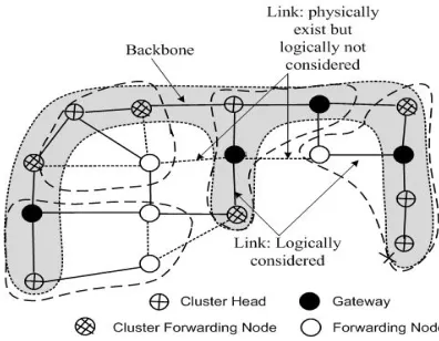
New node determines its status according to the recursive structure of CBNet(G) as follows. Figure 3 represents, if there exists CH(s) in the neighbor of new, new becomes an ordinary node and chooses a CH node as new’s parent. Else if new finds any cluster forwarding node in its neighbor, new becomes an ordinary node and chooses one of the cluster forwarding nodes as new’s parent that has the minimum distance to its CH. Else if new finds any forwarding node in its neighbor, new becomes an ordinary node and chooses one of the forwarding nodes that have the minimum distance to its CH as its parent. Else if new finds any ordinary node in its neighbor who is closer to CH k (k≥ 2), new selects one to be its parent which has the minimum distance to its CH; new becomes an ordinary node and the selected node changes its status to forwarding node. Else if new finds gateway nodes in its neighbor, new selects one as its gateway and new becomes a CH of a new cluster. Else, there are only ordinary nodes in the neighbor of new whose distance to their CHs are already k. New selects one ordinary node as its parent and becomes a CH of a new cluster.
Figure 3 Describes network topology of CBNet(G)
The chosen node then changes its status to gateway node and all other nodes that lie on the path from the gateway node to its CH change their status to cluster forwarding node.
2.3 New Nodes Joining Using LEACH-M
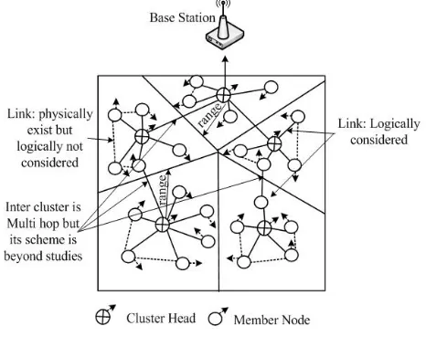
communication. If the new node does not receive acknowledgement within defined timeslot, it considers that it is no more part of the cluster. Therefore, it waits for the next timeslot and sends a join request to new cluster. Once it receives the acknowledgement of the join request, then, it resends the messages to new CH within new timeslot. The CH assigns a timeslot according to the TDMA scheduling for new MN. The cluster formation and data transmission in LEACH-M is divided into two phase those are, setup phase and steady state phase. In setup phase cluster formation happens and after each round cluster is reformed. On the other hand in steady-state stage, data transmission occurs to the BS. Initially, the node is in sleeping stage to reduce energy dissipation. At the time node gets its timeslot, it wakeup and initiates transmission with CH. CH aggregates the data and sends it to the base station. The steady-state stage is longer as compare to the setup stage. Thus, CH and non CH nodes initiate data communication in its timeslot in steady-state stage. Figure 4 describes the Lech-M topology where the intra-cluster communication is single-hop. Nodes in Leach-M are considered to be mobile nodes. Therefore, a node that is out of range, it is no more part of their cluster. Thus, MNs sends a query message to know whether it is still part of cluster or not before data transmission.
2.4 New Nodes Joining Using LEACH-ME
Leach Mobile Enhancement is a Cluster-based protocol which is suitable for new mobile nodes in WSNs [11]. The main idea is to elect the node with low mobility as a CH. To measure the low mobility factor, and consider two important parameters those are, remoteness and time. Remoteness has an association with communication link modification rate. Consequently, this consideration forms uniform speed clusters, where CH has minimum speed in the group. The advantage of such groups is that, the average maintenance is small to maintain high spatial dependency. Thus, node movements do not breakage the relationship of MNs with CH. Remoteness can be measured using mentioned expression. Let ni(t), i = 0,1,2,3,...N-1, where N describes nodes
density, the location vector of sensor node i at time t in equation (i).
And dij(t) = |nj(t) - ni(t)|, the range between sensor
node i to node j at time t. So the remoteness from sensor node i to sensor node j at time t is Rij(t) = F (dij(t)),
where F represents the function of remoteness. Remoteness is distance from node i to node j. Therefore mobile node remoteness with respect to time can be measured via following expression.
Figure 4 Describes Leach-M protocol
. M(𝑡) = 1
𝑁−1∑ |𝑑𝑖𝑗(𝑡)|
𝑁−1
𝑗=0
(i)
Where, dij displays the distance from sensor node ith
to sensor node jth and N shows the number of nodes in the network. The transmission starts of active time slot t1 and it is received at time slot t2. The distance dij(t) =
Radio velocity * (t2-t1). Upon message receiving it is easy to estimate mobility factor of N nodes. The enactment of LEACH-ME is better than LEACH with respect to the energy consumption. Node elects a lesser mobility factor for cluster head to become member node that is estimated at time t.
2.5 New Nodes Joining Using MBC
Mobility based Cluster (MBC) protocol is suggested which is well suitable when new nodes are mobile [12]. MBC takes into consideration of two important parameters for CH election in new nodes which are remaining energy and expected connection time. For CH election considers more remaining energy of the nodes. Moreover, to overcome the problem of packet loss introduces a solution of expected connection time between CH and MNs.
T(n)new = 𝑝
1−𝑝× [𝑟mod (1/𝑝) ] (ii)
× (𝐸𝑛_𝑐𝑢𝑟𝑟𝑒𝑛𝑡 𝐸𝑚𝑎𝑥
𝑣𝑚𝑎𝑥−𝑣𝑛_𝑐𝑢𝑟𝑟𝑒𝑛𝑡
𝑣𝑚𝑎𝑥 ), ∀𝑛 ∈ 𝐺
MBC protocol is established into two phases: setup phase and the steady state phase. In the setup phase each node determine it status either CH or MN based on below formula.
receiving the advertise message, the neighbor new nodes send join request to CH. Upon receiving join request, CH reserves a timeslot for the MN.
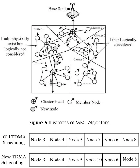
In the steady state phase a join request is broadcasted to CH to improve successful message delivery. Upon acknowledgement of join request MN sends data to CH. Algorithm in [13] also considers the path reliability which is based on path stability or availability of the link between CH and MNs. Both CH and MN maintain cluster time information and broadcast a message when the time hits. As illustrated in Figure 5 a node number 7 leaves its old cluster i.e. cluster 1 and rejoins a new cluster i.e. cluster 4. While a node number 10 leaves its old cluster i.e. cluster 4 and rejoin a new cluster i.e. cluster 1. CHs of cluster 1 and cluster 5 adjust a new TDMA scheduling. In Figure 6 when node 7 leaves the network then its time slot is also removed. The time slot of node 7 is unoccupied. As cluster-head receives the message from new node 10 to join, then a time slot is to be occupied by node 10.
Figure 5 Illustrates of MBC Algorithm
Node 3 Node 4 Node 5 Node 7 Node 6
Node 3 Node 4 Node 5 Node 10 Node 6
Old TDMA Scheduling
New TDMA Scheduling
Node 8
Node 8
Figure 6 Member Node TDMA Time slotting of Cluster 4
The time slotting process is repeated for all new nodes joining and existing nodes leaving.
2.6 New Nodes Joining Using HEED
Hybrid Energy Efficient Distributed Clustering is suggested which is energy efficient clustering [13]. New nodes consider two important parameters for CH election these are; node's residual energy as a primary parameter and node's degree or intra-cluster
communication cost as a secondary parameter for CH head election. For instance, cost could be density of cluster or neighbor proximity. Comparing HEED with LEACH, HEED performs better in terms of enhancing network life time. LEACH elects CH randomly which result few nodes die fast. In HEED each MN is associated with a cluster.
The CHs those are elected in HEED are properly distributed across the network and hence results minimizing clustering cost. The probability of a node to become CH is described in equation (iii).
CHprob = Cprob𝐸𝑟𝑒𝑠𝑖𝑑𝑢𝑎𝑙
𝐸𝑚𝑎𝑥 (iii)
Cprob is a percentage of network nodes to be CH (for example 5%), Eresidual indicates current energy of node, and Emax represents maximum energy. CHprob is not permitted to less than a certain limit of threshold. Therefore, every node executes from certain iteration until it searches the CH. A node becomes a tentative CH if its probability is less than 1. In situation a node becomes MN if it finds other less cost CH. Thus a sensor acts as a permanent CH if its probability reaches to 1. HEED considers multi-hop networks. The considerations of HEED are; (i) a Distribute clustering scheme, where CH election is such a manner to utilize two significant parameters. (ii) Within a specific limit of cycle the clustering process terminates. (iii) Reducing control overhead and (iv) The inter-cluster communication is multi-hop between CH and base station to promote scalability and energy conservations with contrast to single-hop inter-cluster communication.
Figure 7 Describes HEED protocol
Intra-cluster communication is also muti-hop as describe in Figure 7.
3.0 FAULT MANAGEMENT
network, while fault tolerance resolves faults those are detected earlier via diagnose procedure.
3.1 Fault Diagnosis
Fault split the network into virtual groups that might hurdles the smooth data communication in the network. Fault diagnosis is an important consideration to overcame faults in the network. Most of the time the CH acts as a leader that performs fault diagnosis in its group and handle faults through centralized or distributed method.
A silent model is proposed to detect the erroneous behavior to secure healthy nodes from any disturbance [14]. This method uses periodic status updates via inter cluster communication. Sensor node provide their energy status along with data to their cluster head. When the cluster head receives the message, it updates the information of their member nodes’ energy level in its status table and also its own energy information. Cluster head CHi also share this information to other cluster head CHj. At the diagnosis phase if CHj do not receive the message from CHi in its estimated duration, it assumes that the CHi has been died. However, before doing such decision it consults its neighboring CHs about CHi. This approach authenticate the assumption that is drawn for the CHi. Sensor information network architecture is proposed to detect faults in the network [15]. The proposed scheme consists of mechanism for hierarchical clustering. The root node broadcast a SQTL language script to all the cluster head to detect the sensor nodes. Upon receiving the script, cluster head trigger it to their member nodes for energy reading. Cluster head then make a comparison with predefined threshold that received from their member nodes. Member nodes those failed to send their information are identified as faulty sensor nodes.
[16] proposes to detect a heartbeat-style failure diagnosis service implementation. Fault diagnosis is proposed by sharing three types of messages such as Heartbeat message, Digest message and Health-status-update message. In the first round each member node sends a heartbeat message to its cluster head. Meanwhile, the cluster head also broadcast the heartbeat message. Next, each node acknowledge the heart beat message by sending direst message. A node is declared as fault node if the node does not send the heartbeat message nor digest message to the neighboring nodes, which reflects the node is crashed.
When a certain minimum energy level meets, sensor nodes send a "Leave Me" message to quit from the network. The node that receive the message, removes the leaving node information from routing table and rejoin the network [7,8].
3.2 Fault Tolerance
When fault is diagnosed in the network then second important step is to resolve faults, which are performed through fault tolerance procedure. Thus the network
transmission is not suffered due to different faults that might happen the network.
3.2.1 Minimum Connected Dominating Set Approach (MCDS)
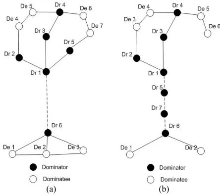
A first centralized algorithm is proposed to establish connected inter-actor network [17]. The idea is to pursue a coordinated actor node movement to join the sub-parts to decrease the entire distance of actor movement. For this purpose they propose the minimum connected dominating set of each sub-network and selecting the right actor movement, thus the connectivity of each sub-network is not breached. However, the repositioned actor might disconnect the sub-networks, therefore, they consider the additional intermediate nodes to perform the movements to maintain the intra sub-network connectivity. Moreover, shorter distance node movement also decreases the total amount of energy. The object of such movement is three folds. (a) To decrease the number of actors to be moved (b) To decrease the total distance that an actor will travel (c) To distribute the load during actor movement so that the actor nodes do not deplete soon. In Figure 8.a, two disjoint graphs are described. Next, the two graphs are joined by moving node Dr 5 and De 2 as describe in Figure 8.b. De 2 also changes its status from dominatee to dominator becomes Dr.7.
(a) (b)
Figure 8 Illustrates MCDS approach
3.2.2 Distributed Connectivity Restoration Algorithm (DCRA)
proposes Distributed Connectivity Restoration Algorithm (DCRA) to investigate cut-vertex. Restoration process is performed by two phases of recovery. (i) Cut-vertex determination and failure detection: Each node the network enquires about its neighbor node status is cut vertex or not based upon the information of its k-hop neighbor. Each node sends HEARTBEAT messages to check the status of 1-hop neighbor list. The node failure is detected based upon missing HEARTBEAT messages.
(ii) Connectivity Restoration: Based on determination of cut-vertex between nodes and failure detection mechanism. DCRA recover the best candidate to recover node failure. Challenging issue is to further avoid partitioning the network during recovery procedure due to node movement. To hand this issue a disconnected precaution mechanism is developed in DCRA.
3.2.3 Node-Move-Out in CNet(G)
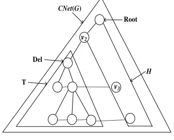
Dynamic Cluster-based Wireless Sensor Network CNet(G) addresses node-move-out algorithm, which describe a node leaving procedure [6, 7]. Gateway, cluster-head and member node are the three possibilities that might leave the network. When member node wants to leave the network, it sends "Leave Me" message to neighboring nodes. Upon receiving the message, neighbor node(s) remove leaving node information from their routing table and leaving node quit from the network. When parent node (Del) wants to leave from the network becomes root node of subtree (T) as describe in Figure 9. Next, Del broadcast "Leave Me" message to child nodes to exit from the network which is a fault diagnosis method. When child node(s) receive the message, it withdraws from subtree T and joins the other subtree H of CNet(G) as describe in Figure 9 which is a fault tolerance method. In rejoin process, the node joins either cluster head gateway or member node depends upon the neighbor node in H.
The merits of structured network provide key features such as minimizing communication overhead, choosing data aggregation, increasing the probability of aggregating redundant data, and minimizing the overall power consumption [6].
3.2.4 Node-Move-Out In CBNet(G)
Novel Cluster-based Wireless Sensor Network CBNet(G) addresses node-move-out algorithm, which describes a node leaving procedure [18]. In node-move-out algorithm, leaving node informs its neighbors and parent node by sending "Leave Me" message which is a fault diagnosis method. Forwarding node, cluster forwarding node, cluster head and gateway are the possibilities that might leave the network.
CNet(G)
H
v2
v3
T Del
Root
Figure 9 Illustrates joining of subtree T with H
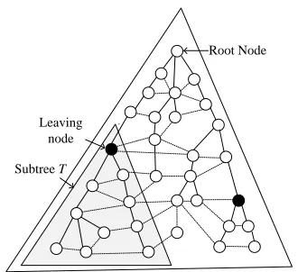
If the leaving node is the leaf node, it sends “Leave Me” message to neighboring node and quit from the network. Upon receiving the “Leave Me” message to neighbor nodes, neighbor nodes remove the leaving node information from its routing table. If leaving node is not a leaf node, leaving node declare itself as a root node of subtree. Afterword, leaving node broadcast “Leave Me” message to its subtree through Eulerian tour as shown in Figure 10. During Eulerian tour “Leave Me” message send to all the subtree until root node receive its own “Leave Me” message. In Eulerian tour when subtree node receives the “Leave Me” message, it quits from the current subtree and rejoin the network which is a fault tolerance method. Since each node has all neighbor information, therefore it join the network either as a ordinary node, forwarding node, cluster forwarding node, cluster head or gateway node. Hence, all the subtree nodes join the network one by one by calling node joining algorithm. When the subtree rejoins the network then the root node which is a leaving node quit from the network.
4.0 DISCUSSION AND OPEN RESEARCH AREAS
IN CLUSTER-BASED WSNs
This section discusses the shortcomings of present self-organized network and then a comparative table is drawn to compare existing self-organized algorithm using the taxonomy framework. This section also presents the future research areas that need to be focused.
4.1 Shortcomings of Self-Organized Network
Table 1 compares WSNs algorithms characteristics. From the table, it is observed that the existing self-organized techniques have the following shortcomings.
The majority of existing work assumed that the nodes are mobile and very less consideration is given to static nodes.
joining are still missing in current literature for static nodes.
Leaving node
Subtree T
Root Node
Figure 10 Illustrates Leaving node from the network
New nodes want to join the network that requires channel access mechanism. The current algorithms do not consider channel access issues. Little work has been done on diagnosing of various
faults, e.g. node malfunctioning, minimum energy threshold.
Most of the works consider single node leaving, however, multiple nodes leaving is still missing. Little work has been done to determine link failure
in different nodes.
Little consideration has been done on security in dynamic network management.
4.2 Important Research Areas
There are critical reach issues related to self-organized network in WSNs, which require extra investigation. The list is as follows.
Multi Nodes Joining in cluster-based network Multi Nodes Leaving in cluster-based network Distributed fault diagnosis technique in WSNs Nodes synchronization during nodes joining and
leaving
Determination of an optimal threshold for node leaving
Adaptability in malicious attack Adaptability of network dynamics
Suitable cluster head election in order to enhance network life time
5.0 CONCLUSION
A self-organized network has the ability to maintain the integrity of a network when nodes join and existing nodes leave the network. Network topology is altered when new nodes join or existing node leave the network. This might halt the normal data communication of the network, hence, self-organize network is the right solution to confirm the smooth data communication. In this paper, new node joining and existing node leaving algorithm are discussed. These algorithms are also examined based upon the performance metrics.
It is investigated that network dynamics is not properly investigated to form a self-organized network. Therefore, self-organized cluster-based WSN is an absolute requirement to handle topological manipulation. This article also provides contemporary issues regarding self-organize network and then addresses future research areas.
Table 1Illustrates comparison of different algorithms
Node Joining Node
Leaving Static or Mobile Node References
Single Node
Joining Single Node Leaving Static [7-8]
Single Node
Joining Single Node Leaving Static [9]
Single Node
Joining Addressed Not Mobile [10]
Single Node
Joining Addressed Not Not Addressed [11]
Single Node
Node Joining Node
Leaving Static or Mobile Node References
Single Node
Joining Addressed Not Not Addressed [13]
Not
Addressed Single Node Joining Mobile [14]
Not
Addressed Single Node Joining Mobile [15]
Not
Addressed Single Node Joining Mobile [16]
Not
Addressed Multi Nodes Joining Mobile [17]
Not
Addressed Multi Nodes Joining Mobile [18]
Single Node
Joining Single Node Leaving Static [7-8]
Single Node
Joining Single Node Leaving Static [9]
Acknowledgement
This work is partially supported by grant GUP Tier 1, 2014-2015 with Reference No. Q.K130000.2543.05H61 and GUP Tier 1 with Vote No. 05H61and GUP Tier 2E with Vote No. 09J73 of Ministry of Higher Education (MoHE) year 2014 to 2015, and Malaysia-Japan and International Institute of Technology and (MJIIT) of Universiti Teknologi Malaysia (UTM).
References
[1] M. Razzaque, C. Bleakley, and S. Dobson. 2013. Compression in Wireless Sensor Networks: A Survey and Comparative Evaluation. ACM Transactions on Sensor Networks (TOSN). 10(5).
[2] E. M. Belding Royer. 2002. Hierarchical Routing in Ad Hoc Mobile Networks. Wireless Communications and Mobile Computing. 2: 515-532.
[3] J. I. Bangash, A. H. Abdullah, M. H. Anisi, and A. W. Khan. 2014. A Survey of Routing Protocols in Wireless Body Sensor Networks. Sensors. 14: 1322-1357.
[4] J. Y. H. Zymunt J. Haas. 2002. Gossip-based Ad Hoc Routing. IEEE Info com 2002. 0-7803-7476-02.
[5] C. E. Perkins. 2001. Performance Comparison of Two On-Demand Routing Protocols for Ad Hoc Networks. IEEE Personal Communication. 1070-9916/01.
[6] N. Vlajic and D. Xia. 2006. Wireless Sensor Networks: to Cluster or Not to Cluster? In Proceedings of the 2006 International Symposium on on World of Wireless, Mobile and Multimedia Networks. 258-268.
[7] J. Uchida, A. M. Islam, Y. Katayama, W. Chen, and K. Wada. 2008. Construction and Maintenance of a Novel Cluster-based Architecture for Ad Hoc Sensor Networks.
Journal of Ad Hoc and Sensor Wireless Networks. 6: 1-31. [8] A. M. Islam, K. Wada, J. Uchida, and W. Chen. 2012. A
Better Dynamic Cluster-Based Structure of Wireless Sensor Network For Efficient Routing. International Journal of
Innovative Computing Information and Control. 8: 6747-6760.
[9] A. M. Islam, Y. Katayama, W. Chen, and W. Wada. 2006. A Novel Cluster-based Architecture and Routing Protocols for Dynamic Ad-hoc Radio Networks. Journal of Electrical Engineering. The Institution of Engineers, Bangladesh. [10] D.-S. Kim and Y.-J. Chung. 2006. Self-organization Routing
Protocol Supporting Mobile Nodes for Wireless Sensor Network. In Computer and Computational Sciences, 2006. IMSCCS'06. First International Multi-Symposiums on. 622-626.
[11] G. S. Kumar, V. Paul, G. Athithan, and K. P. Jacob. 2008. Routing Protocol Enhancement for Handling Node Mobility in Wireless Sensor Networks. In TENCON 2008-2008 IEEE Region 10 Conference. 2: 1-6.
[12] S. Deng, J. Li, and L. Shen. 2011. Mobility-based Clustering Protocol for Wireless Sensor Networks with Mobile Nodes.
Wireless Sensor Systems, IET. 1: 39-47.
[13] O. Younis and S. Fahmy. 2004. HEED: A Hybrid, Energy-Efficient, Distributed Clustering Approach for Ad Hoc Sensor Networks. Mobile Computing, IEEE Transactions on.
3: 366-379.
[14] G. Gupta and M. Younis. 2003. Fault-tolerant Clustering of Wireless Sensor Networks. In IEEE Wireless Commun. Network. 3: 1579-1584.
[15] C. Jaikaeo, C. Srisathapornphat, and C.-C. Shen. 2001. Diagnosis of Sensor Networks. In IEEE International Conference on Communications. 5: 1627-1632.
[16] A. Tai, K. Tso, and W. Sanders. 2004. Cluster-based Failure Detection Service for Large-Scale Ad Hoc Wireless Network Applications. In International Conference on Dependable Systems and Networks. 805-814.
[17]` Senel, F., Akkaya, K., & Younis, M. 2007. An Efficient Mechanism for Establishing Connectivity in Wireless Sensor and Actor Networks. In Proceedings of IEEE GLOBECOM’07. 1129-1133.
[19] A. K. M Islam and A. Zeb. 2013. Communication Protocols on Dynamic Cluster-based Wireless Sensor Network. Informatics, Electronics & Vision (ICIEV), 2013 Conference, Dhaka, Bangladesh.
[20] M. Nafees, et al. 2014. Cognitive Radio Ad-Hoc Network Architectures: A Survey. Wireless Personal Communications. 1-26.
[21] Z. Mahdi, et al. 2014. Mobility-aware Timeout Medium Access Control Protocol for Wireless Sensor Networks. AEU-International Journal of Electronics and Communications. 68.10 (1000-1006).
[22] L Junbin, et al. 2014. A Survey of Coverage Problems in Wireless Sensor Networks. Sensors & Transducers. 1726-5479 163.1.
[23] A Adnan, et al. 2014. A Survey on Trust Based Detection and Isolation of Malicious Nodes in Ad-Hoc and Sensor Networks. Frontiers of Computer Science. 1-17.
[24] A Adnan, et al. 2015. Countering Node Misbehavior Attacks using Trust Based Secure Routing Protocol.
Telecommunication Computing Electronics and Control. 13.1.