Behavior of Prestressed Concrete Containment Vessel(PCCV) under Pressure and
Thermal Loading Histories
Il-Hwan Moon
1), Nam Ho Lee
2), Jong Bo Lee
3), Sang Hoon Noh
3)Chong Hak Kim
3)1)Department of Civil Engineering, Korea Power Engineering Company, Yongin, Korea
2)Department of Advanced CANDU Reactor, Atomic Energy of Canada Limited, Toronto, Canada 3)Nuclear Engineering & Technology Institute, Korea Hydro & Nuclear Power Company, Daejeon, Korea ABSTRACT
This paper describes the nonlinear analyses of a 1:4 scale model of a prestressed concrete containment vessel (PCCV) which incorporates both pressure and temperature effects. In the nonlinear finite element analyses, the 1:4 scale PCCV including the cylindrical vessel, the spherical dome and the concrete base slab are idealized as an axi-symmetric global model with axi-symmetric solid elements and shell elements.
The temperature-dependent degradation properties of concrete and steel are considered. Both geometric and material nonlinearities including thermal effects are also addressed in the analyses. Menetrey and Willam (1995) concrete constitutive model with non-associated flow potential is adopted for this study. This study includes the results of the predicted thermal and mechanical behaviors of the PCCV subject to high temperature loading and internal pressure simultaneously.
In order to find the effect of accident high temperature on the ultimate capacity of each component, two
kinds of analyses are performed; one for pressure only and the other for pressure with temperature. The results are
compared with each other for the liner plate, reinforcement, prestressing tendon and concrete. The analysis results
show that the temperature directly affects the behavior of the liner plate, but have a little impact on the ultimate
pressure capacity of the PCCV.
INTRODUCTION
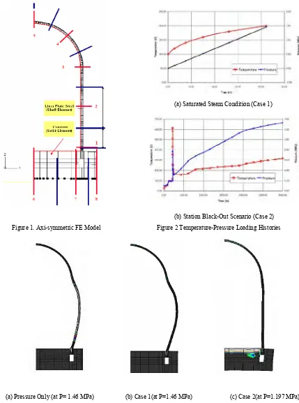
This paper is focused on the behavior of the NUPEC/NRC 1:4-scale prestressed concrete containment vessel under pressure and temperature loading beyond design basis. In the nonlinear finite element analyses, the 1:4-scale PCCV is idealized as an axi-symmetric global model with axi-symmetric solid elements for concrete structure and shell elements for liner plate shown in Figure 1.
In order to find the effect of accident high temperature on the ultimate capacity of each component, two kinds of analyses were performed; a combined thermal-mechanical analysis of the 1:4-scale PCCV model for saturated steam conditions (Case 1) and for a severe accident scenario (Case 2). The numerical results for each case were documented for a reduced set of Standard Output Locations and compared with the numerical results for mechanical (pressure) for liner plate, reinforcement, prestressing tendon and concrete. The computer program ABAQUS [3] was used to analyze the axi-symmetric finite element model of PCCV with nonlinear and temperature-dependent material properties of concrete, liner plate, reinforcing steel, and prestressing tendon.
MATERIAL PROPERTY AND MODELING
Concrete Property and Failure Criteria
The concrete is characterized by a materially nonlinear deformation behavior. The material non-linearity is assumed to occur due to cracking of concrete in tension and plasticity of concrete in compression. However, the material non-linearity due to the latter has relatively less influence than that due to the former on the failure mode of containment structure under internal pressure.
The Menetrey-Willam’s failure model with a non-associated plastic flow that is known to be suitable to represent the tensile concrete cracking of the axi-symmtric finite element model is introduced in the numerical analysis. The yield surface and flow potential parameters for elasto-plastic material yield surface in the Menetrey-Willam’s failure model with non-associated plastic flow and the strain hardening are defined by the model parameters r-factor, the friction angle β, and the dilation angle ψ.The elliptic function
r
(
θ
,
e
)
controls the shape of the yield surface in the deviatoric plane and angleβ
is the angle between the yield surface and the pressure stress axis in the meridian plane [3].The mechanical concrete properties from the uniaxial strength test data of the trial mix concrete are used in the analysis of the 1:4 scale PCCV model for mechanical (internal pressure load only) and thermal-mechanical (pressure + temperature) loading. The uniaxial compressive strength is 39.16 MPa for basemat and 47.30 MPa for shell & dome.
A smooth curve for strength degradation versus temperature as estimated below is introduced into the finite element analysis model.
8 . 1
)
632
/
(
exp
T
S
Rc=
−
, where T is in degree C (1)Further, based on the literature, elastic modulus reduction is calculated by equation (2). 2
/ 1
)
(
RcRc
S
M
=
(2)The thermal expansion coefficient is assumed to be constant at 1.18E-5 cm/cm/oC up to 260oC of temperature rise and
Reinforcement Steels (Rebars)
Rebar materials are generally incompressible when they deform plastically and their yielding is independent of the pressure stress. The von Mises failure criterion is used for this steel material. Hsu [5] noted that the stress-strain curves for bare steel bar and for steel bar embedded in concrete are quite different. Therefore, the stress-strain relationship of rebar embedded in concrete has been used in reinforced concrete structure to simulate the realistic behavior of the rebar in concrete. The stress-strain curve of the rebar for the numerical analysis is idealized by bilinear curve with a slope of Es before yielding
and a slope of Ep after yielding. The test results are used in the numerical modeling of the rebar material properties. Yield
stress and tensile stress are typically 473.1 MPa and 658.3 MPa. Temperature variation of steel is considered in the analysis model as idealized below. The coefficient of the thermal expansion of steel is assumed to be a constant at 1.18E-5 cm/cm/oC.
C
T
for
S
T
S
Rs Rs
o
340
C
0
.
1
]
300
/
)
340
[(
exp
1.9≤
=
−
−
=
where T is in degree C (3)
Prestressing Tendon
The stress-strain curve of a bare prestressing tendon comprised of two straight lines joined by a knee curve is used in the numerical analysis. The first part of the curve is a straight-line up to 0.7fpu and the second part is expressed by
Ramberg-Osgood equation that meets the first part at the stress level of 0.7fpu[5].
The tensile strength of tendon is 1,912 MPa. ABAQUS, the finite element program, has no function to incorporate the unbonded tendon. The prestressing tendons are modeled as rebar subelements in concrete using the embedded approach available in ABAQUS. The numerical modeling of tendons as rebar sub-elements implies that the tendons are assumed bonded to the concrete and slippage of the tendon in the tendon sheath is not considered in the numerical analysis.
Steel Liner Plate
The stress-strain behavior of the liner plate steel is modeled by using elasto-plastic model available in ABAQUS. The von Mises failure surface with kinematic hardening is used to represent the nonlinear behavior of the material. The yield strength and tensile strength are 375.6 MPa and 499.2 MPa, typically.
FINITE ELEMENT MODEL
Model for Shell and Dome
induced in the tendons with a function through the *INITIAL CONDITIONS option in ABAQUS. Model for Base Slab
The base slab is included in the finite element model to simulate the possible vertical uplift of the base during internal pressurization and to estimate the effect of the base slab on the failure mode. The previously described shell and dome model is connected to the base slab model consisting of eight-node solid elements with considering tendon gallery.
The liner plate simulated by three-node shell elements is assumed rigidly connected to the eight-node concrete solid elements unlike those for cylindrical shell since the interaction effect of liner steel and concrete during the flexural deformation of the slab is not significant in the thick base slab of PCCV. Reinforcements in the base slab are estimated from the provided structural drawings and are included in the analysis model. All rebars in the base slab are modeled as those of shell portion by using the rebar subelement of ABAQUS. The bottom of the slab rests on a soil foundation modeled by nonlinear soil springs with tension cut-off.
Prestressing Forces in Tendon
The meridional stress and hoop stress along the length of the tendon in the concrete are estimated with the prestressing losses at the time of testing. The prestressing force was introduced prior to applying the internal pressure and/or thermal loadings to the numerical model. The four types of losses given in specific modeling consideration are (1) the friction between the tendon and the concrete, (2) the elastic shortening of the concrete, (3) the creep and shrinkage of the concrete, and (4) the stress relaxation in the prestressed tendons.
The vertical prestressing forces of 106.27kips before anchoring and 96.04kips after anchoring are introduced from the PCCV Model-General Arrangement. Similarly, the hoop tendon forces of 95.27kips before anchoring and 73.52kips after anchoring are used in the calculation of hoop tendon stress.
Self-weight, Internal Pressure and Thermal Loading
Because of the elastic support below the bottom slab, the effect of the weight of the structure had to be initially considered prior to internal pressurization and/or thermal loading. This is accomplished by specifying a mass proportional load for each material included in the 1:4 scale PCCV model prior to initiating the internal pressure and/or thermal loading. The weights of each material are considered in the numerical model by using the GRAVITY parameter of *DEAD LOAD option of ABAQUS. The loading histories of internal pressure and thermal loading are shown in Figure 2. The temperature time history and pressure time history are applied at nodes of finite element model.
ANALYSIS RESULTS AND DISCUSSION
characterized by the theory of linear elasticity and a crack is initiated at tensile strength. In ABAQUS, cracking is assumed to occur when stress reaches a failure surface, which is called the “crack detection surface”, and the program indicates the cracking automatically.
The behavior under high temperature and pressure loading histories are compared with SFMT test results and the pressure-dependent behavior as shown in Figure 3 and Figure 4. The liners are yielded and/or ruptured at higher pressure when both temperature and pressure were simultaneously applied than when subjected to pressure only.
Displacements
Figure 4(a) shows direct comparisons of analysis results and measured radial displacements versus pressure at various locations under pressure only and/or with thermal loading. As shown in Figures, the radial displacements under pressure only correspond well with the numerical results and the measured displacements from SFMT. A combined mechanical-thermal analysis simulating a saturated steam condition (Case 1) shows that the temperature history starting with 100°C created a sudden increase in displacements at initial stage, but the slopes expressing the pressure-displacement relationship with increasing temperature and pressure appeared very similar to the trend for the pressure only case.
The analysis results for Case 2 show that the displacements due to the sudden increase in temperature and pressure for a very short time period did not fully recover when returned to the starting temperature and pressure. This can be interpreted as a sort of residual deformation from damage to the liner plate and/or concrete portion due to instantaneous high temperature and pressure loading. Unfortunately, the analysis for Case 2 was stopped at 1.1974 MPa due to divergence and the behaviors could not be investigated beyond 1.1974 MPa.
To evaluate the effects of the liner expansion caused by high temperature during very short periods on the structural behavior, a case (Case 3) of analysis was additionally performed with high temperature (Case 2 temperature history) applied only to the liner under pressure loading assuming no transfer of temperature to the concrete portion. The analysis results show that the displacements due to liner expansion do not increase significantly in comparison with those due to the pressure loading only, except for the vertical displacements in the dome portion.
Strains in Reinforcements
To confirm the numerical model for rebars, the recorded residual strain at the beginning of SFMT was subtracted from the measured strains and compared with those from numerical analysis under pressure only. Figure 4(b) shows that the strains in the reinforcements under pressure only compare well with the numerical results and the measured displacements from SFMT. A combined mechanical-thermal analysis simulating a saturated steam condition (Case 1) shows that the thermal loading history starting with 100°C created abrupt increase in strains at initial stage similar to the displacements, but the slopes expressing the pressure-displacement relationships with increasing temperature and pressure appeared closer to the trend for pressure only.
short durations, do not fully recover back to the strains at initial pressure and temperature. This can be interpreted as sort of residual deformations from damage to liner plate and/or concrete portion due to instantaneous high temperature and pressure loading. The residual strains remained in the inner layer of rebar around wall-mat junction during abrupt change of temperature. Unfortunately, the analysis for Case 2 was stopped at 1.1974Mpa due to divergence and the behaviors could not be investigated. The ultimate capacity may drop rapidly with a sudden increase in deformation which in turn will induce divergence.
Liner and Tendon Strains
The strains in the liner from the numerical analyses for pressure only, saturated steam condition (Case 1) and severe accident scenario (Case 2) were compared with each other. Case 2 shows that the stresses in liner were under compressive behavior at pressures between 0.2 MPa and 0.78 MPa and temperature between 100°C and 615°C) for short periods of around 260 through 300 minutes(see Figure). The buckling stress considering the horizontal spacing of liner anchor (150.15mm) is calculated to 122.2Mpa and thus most of stresses of Case 1 and Case 2 are beyond the calculated buckling stress.
Tendon strains under both temperature and pressure are increased in comparison with those under pressure only (see Figure 4). Temperature has definitely an effect on the ultimate pressure capacity of PCCV.
Concrete Cracking
The finite element analysis under internal pressure only results show that the first concrete cracking in the numerical model occurs at a pressure level of 0.60 MPa and is located at the surface of cylindrical wall at the wall and basemat joint. At the pressure level of 0.64 MPa, the elements at mid-height of wall cylinder are cracked in both the hoop and meridional directions.
REFERENCES
[1] Dameron, R.A., Wolohan, M., Hansen, B. and Kelley,E., Analysis of Axisymmtric Prestressed Concrete Containment Vessel (PCCV) Including Thermal Effects; A summary of Temperature Section Result, Analytical Assumption and
Technical Approach for use by the ISP 48 Analysis Exercise Participants, David Evans and Associates, inc. and Sandia National Laboratories, August 2004.
[2] Holmes, M., Anchor, R.D., Cook, M.D. and Crook, R.N., The Effects of Elevated Temperatures on the Strength Properties of Reinforcing and Prestressing Steels, The Structural Engineer, Vol. 60B, No. 1, March 1982
[3] ABAQUS User’s Manual, Version 6.4, 2003. ABAQUS Inc.
[4] Hessheimer, M.F., Klamerus, E.W., Lambert, L.D. and Rightley, G.S., Overpressurization Test of a 1:4-Scale Prestressed Concrete Containment Vessel Model, NUREG/CR-6810, SAND2003-0840P, Sandia National Laboratories, Albuquerque, March 2003.
(a) Saturated Steam Condition (Case 1)
(b) Station Black-Out Scenario (Case 2) Figure 1. Axi-symmetric FE Model Figure 2 Temperature-Pressure Loading Histories
(a) Radial Displacement (b) Hoop Rebar Strain
(c) Meridional Liner Strain (d) Hoop Tendon Strain Figure 4 Comparisons of Test Results and Analysis Results
LOCATION #38 -1000 -750 -500 -250 0 250 500 750 1000
0.000 0.250 0.500 0.750 1.000 1.250 1.500 1.750 2.000
Load (MPa) L in e r S tr e s s ( M P a )
PRESSURE ONLY CA SE 1 CA SE 2 CA SE 3
(EL. 6.58m, Az. 135 Deg.)
-0.005 0.000 0.005 0.010 0.015 0.020 0.025
0.00 0.25 0.50 0.75 1.00 1.25 1.50 1.75 2.00
Load (MPa) T e n d o n S tr a in
P R ES S URE O NLY CA S E 1 CA S E 2 CA S E 3
LOCATIO N #6
0.00 40.00 80.00 120.00 160.00
0.00 0.25 0.50 0.75 1.00 1.25 1.50 1.75 2.00
Load (MPa) R a d ia l D is p . (m m )
SFMT PHA SE 2 PRESSURE ONLY CA SE 1 CA SE 2 CA SE 3
LOCATION #22 -0.010 0.000 0.010 0.020 0.030
0.00 0.25 0.50 0.75 1.00 1.25 1.50 1.75 2.00
Load (MPa) R e b a r S tr a in